2006 LAND ROVER FRELANDER 2 spark plugs
[x] Cancel search: spark plugsPage 616 of 3229
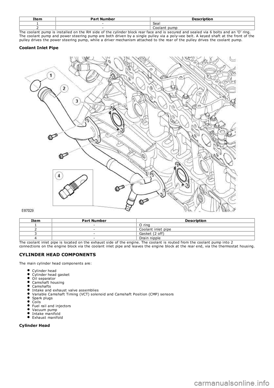
ItemPart NumberDescription1-Seal2-Coolant pumpThe coolant pump is ins t alled on t he RH side of t he cylinder block rear face and is s ecured and s ealed via 6 bolt s and an 'O' ring.The coolant pump and power s t eering pump are bot h driven by a single pulley via a poly-vee belt . A keyed s haft at the front of t hepulley drives t he power s teering pump, while a driver mechanism at t ached to t he rear of t he pulley drives the coolant pump.
Coolant Inlet Pipe
ItemPart NumberDescription1-O ring2-Coolant inlet pipe3-Gas ket (2 off)4-Drain nippleThe coolant inlet pipe is locat ed on t he exhaus t s ide of the engine. The coolant is rout ed from t he coolant pump int o 2connect ions on the engine block via t he coolant inlet pipe and leaves t he engine block at t he rear end, via t he t hermos tat hous ing.
CYLINDER HEAD COMPONENTS
The main cylinder head component s are:
Cylinder headCylinder head gas ketO il s eparat orCams haft hous ingCams haftsIntake and exhaust valve ass embliesVariable Cams haft Timing (VCT) s olenoid and Cams haft Posit ion (CMP) sens orsSpark plugsCoilsFuel rail and injectorsVacuum pumpIntake manifoldExhaus t manifold
Cylinder Head
Page 625 of 3229
For addit ional information, refer t o: Elect ronic Engine Cont rols (303-14A Elect ronic Engine Controls - I6 3.2L Pet rol, Des cript ion andOperation).
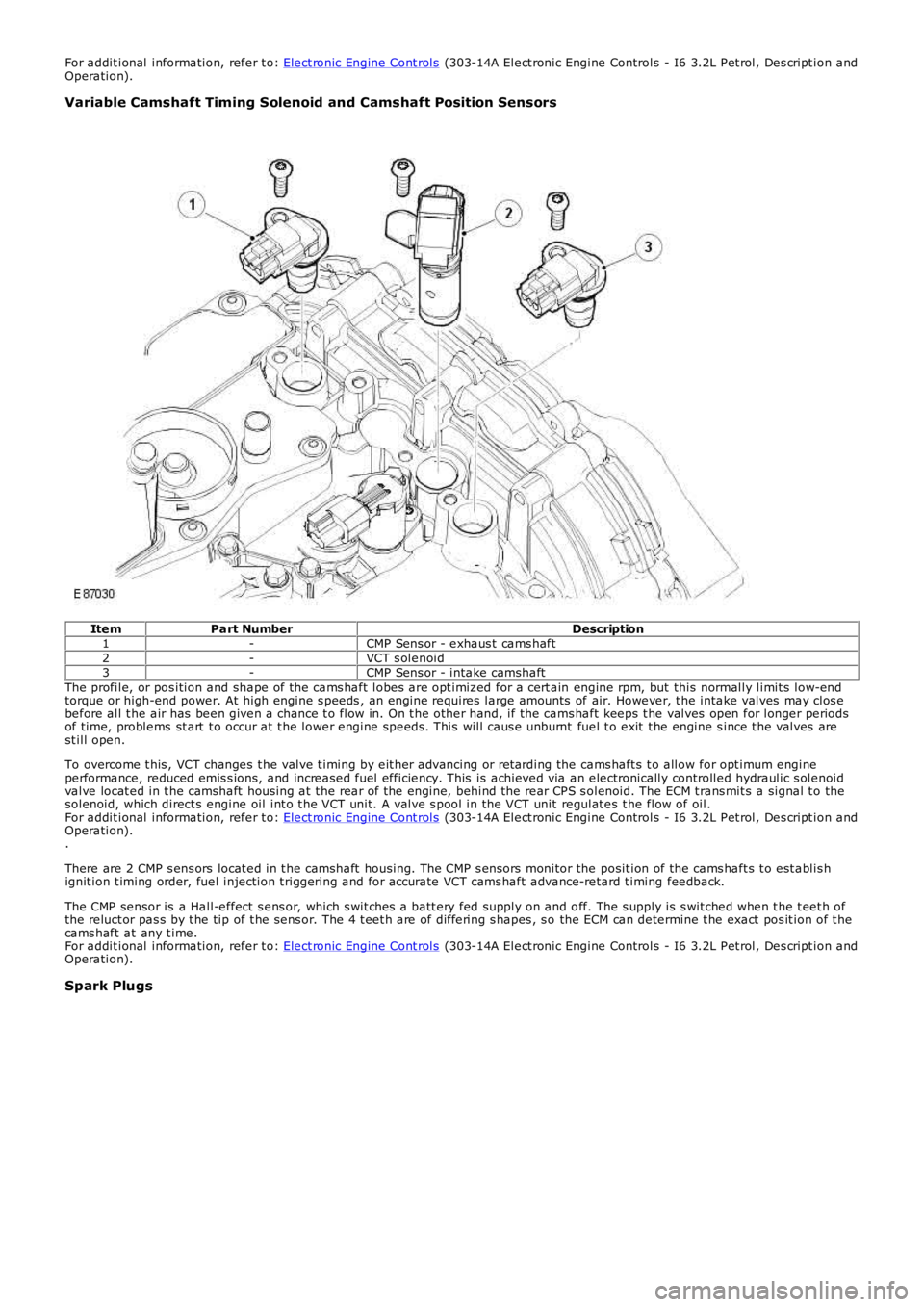
Variable Camshaft Timing Solenoid and Camshaft Position Sensors
ItemPart NumberDescription1-CMP Sens or - exhaus t cams haft2-VCT s olenoid3-CMP Sens or - intake camshaftThe profile, or pos ition and shape of the cams haft lobes are opt imiz ed for a cert ain engine rpm, but this normally limit s low-endtorque or high-end power. At high engine s peeds , an engine requires large amounts of air. However, t he intake valves may clos ebefore all t he air has been given a chance t o flow in. On t he other hand, if the cams haft keeps t he valves open for longer periodsof time, problems st art t o occur at t he lower engine speeds . This will caus e unburnt fuel t o exit t he engine s ince t he valves arest ill open.
To overcome t his , VCT changes t he valve t iming by eit her advancing or ret arding the cams haft s t o allow for opt imum engineperformance, reduced emis s ions, and increased fuel efficiency. This is achieved via an electronically controlled hydraulic s olenoidvalve locat ed in t he camshaft housing at t he rear of t he engine, behind the rear CPS s olenoid. The ECM t rans mit s a signal t o thesolenoid, which direct s engine oil int o t he VCT unit. A valve s pool in the VCT unit regulat es t he flow of oil.For addit ional information, refer t o: Elect ronic Engine Cont rols (303-14A Elect ronic Engine Controls - I6 3.2L Pet rol, Des cript ion andOperation)..
There are 2 CMP s ens ors locat ed in t he camshaft housing. The CMP s ensors monitor the posit ion of the cams haft s t o est ablis hignit ion t iming order, fuel injection t riggering and for accurate VCT cams haft advance-retard t iming feedback.
The CMP sensor is a Hall-effect s ens or, which s wit ches a batt ery fed supply on and off. The s upply is s wit ched when t he t eet h ofthe reluct or pas s by t he tip of t he sens or. The 4 t eet h are of differing s hapes , s o the ECM can determine t he exact pos it ion of t hecams haft at any t ime.For addit ional information, refer t o: Elect ronic Engine Cont rols (303-14A Elect ronic Engine Controls - I6 3.2L Pet rol, Des cript ion andOperation).
Spark Plugs
Page 626 of 3229
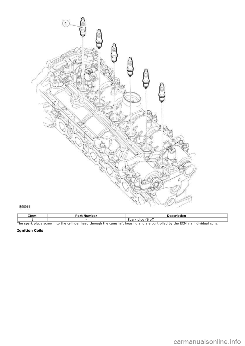
ItemPart NumberDescription1-Spark plug (6 of)The s park plugs s crew into t he cylinder head t hrough the cams haft hous ing and are controlled by the ECM via individual coils .
Ignition Coils
Page 646 of 3229
Publi s hed: 11-May-2011
Engine - I6 3.2L Petrol - Engine
Diagnosi s and Tes ti ng
Principles of Operation
For a detail ed descripti on of the engine sys tem, refer t o t he rel evant Des cript ion and Operat ion s ecti on in the works hopmanual.REFER to: Engine (303-01A Engine - I6 3.2L Pet rol , Des cri pti on and Operati on).
Inspection and Verification
1. Verify t he cus t omer concern.1.
2. Vis ually ins pect for obvious s igns of mechani cal or electrical damage.2.
Visual Inspection
MechanicalElectrical
Coolant leaksOi l leaksLeaks in t he fuel s yst emVis i bl y damaged or worn partsLoose or mis s ing fixings
Fus esLoos e or corroded el ect ri cal connectorsHarnes sesSens ors
3. If an obvious cause for an obs erved or report ed concern is found, correct t he caus e (if pos s ible) beforeproceeding t o t he next s t ep3.
4. If t he caus e is not vis ually evi dent , verify t he sympt om and refer t o t he Sympt om Chart.4.
Symptom Chart
• NOTE: If an engi ne is sus pect , when the vehicl e remai ns under t he Manufact urers warranty refer t o t he W arranty Pol icyand Procedure manual (s ect ion B1.2), or determine if any pri or approval programme is in operat ion, pri or t o t he i ns t allat ionof a new engine.
• NOTE: Due t o t he poss ibi li ty of l oos e carbon, that has become trapped bet ween t he val ve face and s eat, effect ing thepres s ure readi ngs , when carryi ng out a compres s ion t est and s ome cyli nders are found t o have low press ures , i ns t all thes park plugs , road t est the vehicle and re-t es t the s us pect cylinders . If the correct pres sures are rest ored, no furt her acti onis required.
SymptomAction
All engine relat ed is s uesCheck ECM for Di agnos t ic Trouble Codes (DTCs) and refer t o DTC Index.REFER t o: El ect ronic Engi ne Cont rol s (303-14A El ect roni c Engi ne Cont rol s - I6 3.2LPet rol, Di agnos is and Tes ti ng).
Di fficul t t o s tart hot andcoldCarry out general engi ne checks :- Compress ion tes t. Refer t o component t es ts i n t his s ect ion.- Val ve cl earances .REFER t o: Val ve Clearance Check (303-01A Engine - I6 3.2L Pet rol , GeneralProcedures ).- Spark pl ug condi ti on and col or
Poor idleEns ure t he air i ntake s yst em is free from leaksCarry out general engi ne checks :- Compress ion tes t. Refer t o component t es ts i n t his s ect ion.- Val ve cl earances .REFER t o: Val ve Clearance Check (303-01A Engine - I6 3.2L Pet rol , GeneralProcedures ).- Spark pl ug condi ti on and col orCheck for collaps ed catalyt ic converter/blocked exhaus t s ys t emCheck long and s hort t erm fuel t rim datal ogger s ignals- Readings up t o 10%: may be cons idered as acceptable if t he readings are equalbank t o bank- Pos it ive readi ngs of bet ween 10-20%: check for air leaks i n air i nt ake s ys t em- Negati ve readings of between 10-20%: check for over fuell ing e.g. leaki ngi njectors , high fuel pres sure- Readings above 20%: check for DTCs and refer t o DTC Index.REFER t o: El ect ronic Engi ne Cont rol s (303-14A El ect roni c Engi ne Cont rol s - I6 3.2LPet rol, Di agnos is and Tes ti ng).Carry out a vacuum gauge check. Refer to component t es ts i n t his s ecti on.
Insuffi ci entpower/Ins ufficientcompres s ion
Ens ure t he air i ntake s yst em is free from leaksCarry out general engi ne checks :- Compress ion tes t. Refer t o component t es ts i n t his s ect ion.- Val ve cl earances .REFER t o: Val ve Clearance Check (303-01A Engine - I6 3.2L Pet rol , GeneralProcedures ).- Spark pl ug condi ti on and col orCheck for collaps ed catalyt ic converter/blocked exhaus t s ys t emCheck long and s hort t erm fuel t rim datal ogger s ignals- Readings up t o 10%: may be cons idered as acceptable if t he readings are equalbank t o bank
Page 1111 of 3229
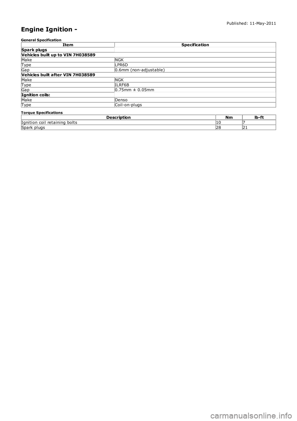
Publi s hed: 11-May-2011
Engine Ignition -
General SpecificationItemSpecification
Spark plugs
Vehicles built up to VIN 7H038589MakeNGK
TypeLPR6D
Gap0.6mm (non-adjust able)Vehicles built after VIN 7H038589
MakeNGK
TypeILRF6BGap0.75mm ± 0.05mm
Ignition coils:
MakeDensoTypeCoil-on-pl ugs
Torque SpecificationsDescriptionNmlb-ft
Igni ti on coi l ret aining bolt s107
Spark pl ugs2821
Page 1120 of 3229
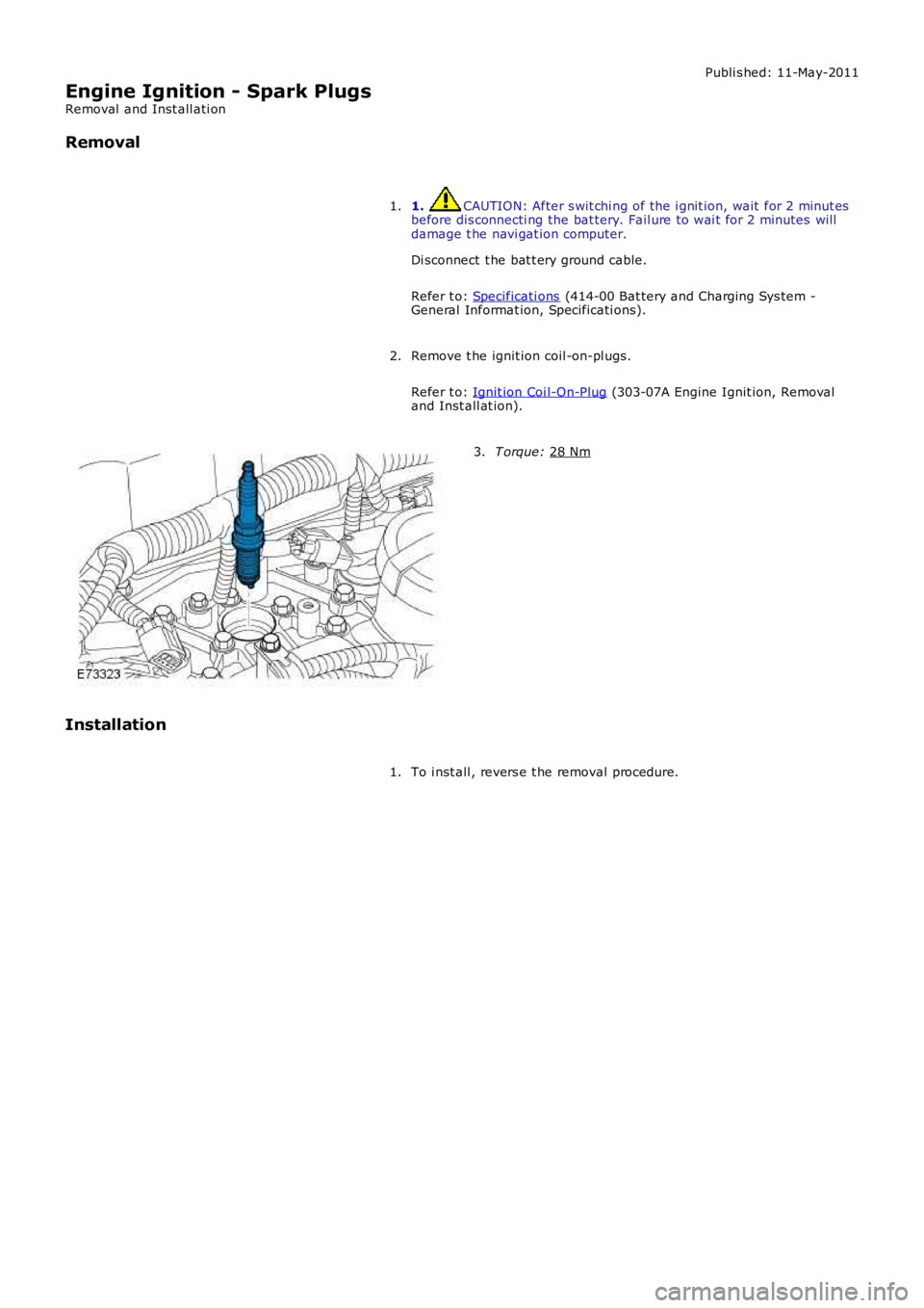
Publi s hed: 11-May-2011
Engine Ignition - Spark Plugs
Removal and Inst all ati on
Removal
1. CAUTION: After s wit chi ng of the i gnit ion, wait for 2 minut es
before dis connecti ng the bat tery. Fail ure to wai t for 2 minutes will
damage t he navi gat ion computer.
Di sconnect t he bat t ery ground cable.
Refer t o: Specificati ons (414-00 Bat tery and Charging Sys tem -
General Informat ion, Specificati ons).
1.
Remove t he ignit ion coil -on-pl ugs.
Refer t o: Ignit ion Coi l-On-Plug (303-07A Engine Ignit ion, Removal
and Inst all at ion).
2. T orque:
28 Nm 3.
Installation To i nst all , revers e t he removal procedure.
1.
Page 1219 of 3229
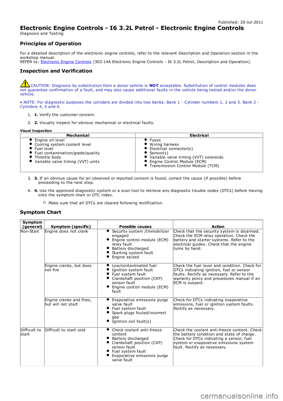
Publi shed: 20-Jul-2011
Electronic Engine Controls - I6 3.2L Petrol - Electronic Engine Controls
Diagnosi s and Tes ti ng
Principles of Operation
For a detail ed descripti on of the el ect ronic engi ne cont rols , refer to the relevant Des cri pti on and Operati on s ect ion i n t heworks hop manual .REFER to: Elect ronic Engine Cont rols (303-14A El ect ronic Engine Cont rols - I6 3.2L Petrol, Des cript ion and Operat ion).
Inspection and Verification
CAUTION: Di agnos is by s ubs ti tut ion from a donor vehicle is NO T acceptabl e. Subs ti tut ion of cont rol modules doesnot guarant ee confirmat ion of a faul t, and may als o caus e addit ional fault s i n t he vehi cl e being t est ed and/or t he donorvehi cl e.
• NOTE: For di agnos t ic purpos es the cyli nders are divided i nt o t wo banks: Bank 1 - Cyl inder numbers 1, 2 and 3. Bank 2 -Cylinders 4, 5 and 6.
1. Verify t he cus t omer concern.1.
2. Vis ually ins pect for obvious mechani cal or electrical fault s .2.
Visual Inspection
MechanicalElectricalEngine oil l evelCooli ng sys t em cool ant levelFuel l evelFuel contami nati on/grade/quali tyThrot tl e bodyVari abl e valve t iming (VVT) uni ts
Fus esW iring harnes sEl ect ri cal connector(s )Sens or(s)Variable val ve ti ming (VVT) s ol enoi dsEngine Cont rol Module (ECM)Trans mi s si on Control Module (TCM)
3. If an obvious cause for an obs erved or report ed concern is found, correct t he caus e (if pos s ible) beforeproceeding t o t he next s t ep.3.
4. Us e the approved di agnos ti c s ys t em or a s can t ool t o ret rieve any diagnos t ic t rouble codes (DTCs ) before movingont o t he sympt om chart or DTC i ndex.
Make s ure t hat all DTCs are cl eared fol lowing recti fi cat ion.
4.
Symptom Chart
Symptom(general)Symptom (specific)Possible causesActionNon-St artEngine does not crankSecuri ty s ys tem /Immobi lizerengagedEngine cont rol module (ECM)relay faultBat tery dis chargedSt art ing s ys tem faultEngine sei zed
Check t hat t he s ecurit y s ys t em i s dis armed.Check t he ECM rel ay operati on. Check t hebat tery and s tarter s yst ems . Refer to theel ect ri cal guides . Check t hat the engineturns by hand.
Engine cranks, but doesnot fi reLow/cont aminated fuelIgnit ion s ys tem faultFuel s ys t em faul tCranks haft pos it ion (CKP)sens or faultEngine cont rol module (ECM)fault
Check t he fuel level and condit ion. Check forDTCs indicati ng ignit ion, fuel or s ens orfault s. Recti fy as neces sary. Refer to t hewarrant y policy and procedures manual if anECM is sus pect .
Engine cranks and fi res ,but wil l not s t artEvaporat ive emi ss ions purgeval ve faultFuel s ys t em faul tSpark plugs foul ed/incorrectgapIgnit ion coil faul t(s )
Check for DTCs i ndi cat ing evaporat iveemis s ions, fuel or i gni ti on s ys t em fault s.Rect ify as neces sary.
Di fficul t t os tartDiffi cul t to s tart coldCheck cool ant ant i-freezecontentBat tery dis chargedCranks haft pos it ion (CKP)sens or faultFuel s ys t em faul tEvaporat ive emi ss ions purgeval ve fault
Check t he cool ant ant i-freeze content. Checkthe bat tery condit ion and s t ate of charge.Check for DTCs i ndi cat ing a s ens or, fuelsys tem or evaporat ive emi s si ons sys temfault . Rect ify as neces s ary.
Page 2849 of 3229

129
Driving hints
R
ECONOMICAL DRIVING
There are two main factors which influence fuel
economy, the way the vehicle is driven, and
maintenance.
Driving tips for economy
• Avoid unnecessary jour neys, especially
short stop-start trips.
• Accelerate smoothly and gently from a
stand still.
• Use the gears to avoid labouring, or
over-revving the engine.
• Allow time to brake gently and smoothly.
• Be aware of traffic and road conditions
ahead, and take action in time to avoid
hard braking or acceleration.
• When stationary apply the park brake, and
select neutral.
• Turn off the air conditioning when not
needed.
Maintenance and fuel economy
Regular servicing by a Land Rover
Dealer/Approved repairer, along with regular
checks by the driver are essential for vehicle
longevity and fuel economy.
The condition of the engine (oils, filters, spark
plugs, settings etc) tyre pressures, and wheel
alignment, will all have a bearing on fuel
economy. For this reason it is essential that the
vehicle is checked regularly by the driver, and
serviced by an approved Land Rover
Dealer/Authorised Repairer at the correct
intervals.
Note: If you are in any doubt about the
maintenance requirement s, intervals, or
checks required, contact your Land Rover
Dealer/Authorised repairer for advice.