2006 LAND ROVER FRELANDER 2 engine overheat
[x] Cancel search: engine overheatPage 36 of 3229
Dust
Dus t or powder produced during repai r operati ons may be irri tant , harmful or t oxi c. Avoid breathing dus t s from powderychemical mat eri als or t hos e aris ing from dry abrasi on operati ons. W ear respi rat ory prot ect ion if vent il ati on is inadequate.
Fine dus ts of combus ti bl e mat eri al can pres ent an expl osi on hazard. Avoid expl os i ve li mit s and s ources of ignit ion.
Electrical Equipment
Electric s hock can res ul t from the us e of faul ty el ect ri cal equipment or from t he misus e of equipment in good condit ion.
Make s ure t hat elect rical equipment i s maint ained in good condit ion and frequent ly tes ted. Fault y equi pment should belabell ed and preferably removed from t he work st ati on.
Make s ure t hat fl exes , cabl es , plugs and s ocket s are not frayed, ki nked, cut, cracked or ot herwi se damaged. If us i ng cablereel extens ion equipment, ALW AY S ens ure that t he cabl e is full y unwound from t he reel .
Make s ure t hat elect rical equipment and flexes do not come int o cont act wi th water.
Make s ure t hat elect rical equipment i s prot ect ed by the correct rat ed fus e.
Never mis use elect rical equipment and never us e equipment which i s in any way fault y. The res ult s coul d be fatal.
Make s ure t hat the cables of mobil e elect rical equi pment cannot get t rapped and damaged, s uch as i n a vehicle hoi st .
Make s ure t hat the des ignated el ect ri cal workers are trained in bas i c Fi rs t Ai d.
In cases of electrocution:
Swit ch off t he power supply before approachi ng t he victi m.If this is not poss i bl e, DO NO T T OUCH T HE VICT IM but push or drag t he pers on from the s ource of electricit yus ing dry, non-conduct ive mat erial .Commence res us ci tat ion i f trained t o do s o.SEEK IMMEDIAT E MEDICAL AT T ENT ION.
Exhaust Fumes
Thes e contai n as phyxiat ing, harmful and t oxic chemicals and part icl es such as carbon oxides , nit rogen oxi des, al dehydes ,lead and aromati c hydrocarbons . Engi nes should be run onl y under condi ti ons of adequat e exhaus t extract ion or generalvent il ati on and not in confi ned spaces .
Gasoline (Petrol) engine
There may not be adequate warning of odour or of i rrit at ion before t oxic or harmful effect s ari se. These may be i mmediat eor del ayed.
Gas Oil (Diesel engine)
Soot , dis comfort and irri tat ion us ual ly gi ve adequate warning of hazardous fume concent rat ions .
Fibre Insulation
The fi brous nature of s urfaces and cut edges can caus e s kin irri tat ion. Thi s is us uall y a physi cal and not a chemical effect .
Precaut ions s hould be taken to avoi d exces s ive s kin contact through careful organi zat ion of work pract ices and the us e ofgloves.
Fire
Many of the materials found on or ass ociated wit h t he repair of vehi cles are highly flammabl e. Some give off t oxic orharmful fumes i f burnt; ot hers s uch as fl uoroelas tomers when burnt or damaged by exces si ve heat can break down andproduce highly corrosi ve hydrofl uoric acid - See Fl uoroelas tomers.
Shoul d any mat erial be i n a burnt or overheated condit ion, handle wit h extreme caution and wear protecti ve clothi ng whenhandl ing s uch it ems . Dis pose of s uch mat erial i n accordance wit h l ocal regulat ions .
Decont aminate and dis pos e of protecti ve cl othing immedi at ely after us e.
Obs erve s trict fire s afety when st ori ng and handl ing flammabl e mat erial s or sol vent s, parti cularly near electrical equi pmentor welding proces s es.
Make s ure, before usi ng electrical or wel ding equipment, t hat there is no fi re hazard present .
Have a s uit abl e fire exti nguis her avai lable when us i ng welding or heati ng equipment.
First Aid
Apart from meeti ng any legal requirement s it is des irabl e for s omeone in the workshop t o be t rai ned in Fi rs t Aidprocedures.
Splas hes in t he eye s houl d be flus hed carefull y wit h clean wat er for at leas t ten minut es .
Soiled ski n s houl d be was hed wit h s oap and water.
Page 297 of 3229
If a fault occurs i n t he Terrai n Res pons e rot ary cont rol, al l rotary cont rol i con amber Light Emi tt ing Di odes (LED's ) wil l bet urned off and rotat ion of t he rot ary control i s ignored. The i ns t rument clus ter mess age cent er will di spl ay a mes s age'SY STEM FAULT SPECIAL PROGRAMS NOT AVAILABLE' when t he fault occurs , if t he fault i s pres ent and the driver att emptst o s el ect a s pecial program (if t he cont rol module is able to do thi s) or at t he next i gni ti on mode 2 (on) cycle.
The Terrai n Res pons e rotary cont rol and t he cont rol module are an i nt egral unit . If a fault occurs in eit her component , thewhole uni t wil l requi re replacement. ENSURE T HAT T HE FAULT IS WIT H T HE T ERRAIN RESPONSE CO NT ROL MO DULEAND NOT IN A SUB-SYST EM MODULE BEFO RE REPLACING T HE MODULE.
If a CAN faul t exi s ts and prevent s Terrai n Res pons e s yst em operat ion, all of t he Terrai n Res pons e rotary cont rol icon LED'swil l be il lumi nat ed and rot ati on of the rot ary cont rol i s ignored.
If the i nst rument clus ter does not receive a Terrain Res ponse s ys t em CAN mess age from the Terrain Res ponse cont rolmodule, t he mes sage 'SY STEM FAULT SPECIAL PROGRAMS NO T AVAILABLE' wi ll be dis played when t he faul t occurs and willbe repeat ed at every ignit ion mode 2 (on) cycl e.
User Error
The fol lowing incorrect us age of t he s yst em may be mi si nterpreted as a s ys t em fault :
Engi ne not running - Program changes and driver advi s ory mes s ages are only avail abl e wi th the engine runni ngSpeci al program change att empted wi th DSC or ABS acti ve (t his i ncl udes ABS cycling which is operat ional when HDCis bei ng used on s lippery or l oose surfaces)Speci al program change att empted wi th overheat condi ti on pres ent on the act ive on-demand coupling.
Page 321 of 3229
Not s ens it ive to brake tes ti ng on a chas si s dynamomet er.
Generati on 4 Acti ve On-Demand Coupli ng - Vehicles from 2009MY
The generati on 4 coupl ing does not have the di fferenti al s peed dri ven pump used on the previ ous generat ion 3coupl ing, but i s fit ted wi th a bigger capacit y electrically operated axial pump and a hi gh pres s ure accumul ator.The proport ional throt t le valve and press ure s ens or on t he generat ion 3 coupli ng is replaced wit h a proport ionalpres s ure reducing val ve.The t orque li mit er pres sure reducing valve on the generat ion 3 coupli ng is replaced by an electroni c cont rol valveand cont rol ling software.
The generati on 4 acti ve on-demand coupli ng gives t he fol lowing improvements over t he previous generati on 3 coupl ing:
Reduced bas e t orque at high different ial s peedsTorque acti vat ion i s now i ndependent of different ial s peedAccurat e t orque l imi ter cont rolEnergy s tored in hi gh pres s ure accumul ator givi ng a low maximum current consumpt ion of t he electric pump andfas t er res pons e.
Control Module - G eneration 3 and 4 Couplings
The cont rol module, at tached to the cas ing of t he act ive on-demand coupling, forms a s ingle unit wit h t he cont rolvalve/axial s ol enoi d. By anal yzi ng informat ion from other vehi cl e modules and s ensors t he cont rol module regul ates t heaxial sol enoi d t o cont rol t he hydraul ic flui d pres s ure s uppl ied t o t he clut ch pl ates. Some of t he modul es and s ens ors thecont rol module communi cat es wit h are li s ted below:
Hardwi red:- Control valve / axi al s olenoid- Electric hydrauli c pump- Oi l press ure and temperat ure sens orHigh speed CAN (cont rol ler area net work):- Engine cont rol module- Anti -l ock brake s ys t em / t racti on cont rol module- Tracti on res ponse swit ch- Y aw rate sens or- Steering wheel rot at ion sens or
The axial sol enoi d cons t ant ly adjust s t he cont rol valve output us ing a Pul se W i dt h Modulat ion (PW M) s i gnal. The flui dpres s ure deli vered t o t he cl utch plat es determines t he amount of t orque t hat is delivered t o t he rear axl e.
The act ive on-demand coupli ng has int egrated oi l press ure and temperature s ens ors to enable the control modul e t oaccurat ely manage t he t orque t ransfer under all environment al and operat ing condit ions . Usi ng thes e s ignals the controlmodule will us e s t rategi es to protect the coupli ng from overheati ng; in extreme cas es to protect t he coupli ng from damaget he coupli ng wil l dis engage i f the t emperat ure of t he hydraul ic flui d exceeds 105°C. The coupl ing wi ll ret urn to normalfuncti onal it y when t he temperat ure fall s below 101°C.
The cont rol module has an int egrated di agnos ti cs sys tem, whi ch cons tant ly moni tors the act ive on-demand couplings ys t em as wel l as it s input and output s ignals . If t he control modul e detects a fault a Diagnost ic Troubl e Code (DTC) i ss tored. The DTC is acces s ed usi ng t he Land Rover approved di agnos t ic s yst em.
Electric Hydraulic Pump
W hen negoti ati ng very low frict ion s urfaces s uch as wet gras s , snow or i ce; i nit ial wheel -s pin can cut i nt o t he s urface andreduce gri p. W it h a re-act ive on-demand coupl ing, almos t 60 degrees of wheel rotat ion woul d occur before torque could bet ransmit ted t hrough t he coupl ing.
On Generat ion 3 coupli ngs , t o count eract thi s Land Rover devel oped a uni que high-pres s ure pre-charge faci li ty whi chenergizes t he hydraul ic circui t as s oon as the engi ne is s t art ed. Es s ent ial ly an el ect ri cal ly operat ed hydraul ic pump wasdesi gned to maintai n a pot ent ial of 500 Nm (369 l b ft ) of t orque pres s ure wi thi n the coupli ng. (This pre-charge t orquecapacit y has been increas ed to 1500Nm (1106 l b ft ) for t he Generat ion 4 coupli ng.)
Vehicles fit ted wi th Terrai n Res pons e als o add furt her benefi ts by varying t he level of pre-charge t o deli ver opti mumt racti on over a range of di fferent t errai n s urfaces . The level of pre-charge is varied dependi ng on t he part icul ar terrainres ponse mode, for exampl e:
Terrai n respons e in 'Speci al Programs Off' mode as common wit h vehi cl es wit hout terrain res pons e, the coupli ng isprogrammed t o transmit 500 Nm 369 lb ft of t orque on Generat ion 3 couplings and 1500 Nm (1106 l b ft) of t orqueon Generat ion 4 couplings t o t he rear axle when the vehicle moves from res t i n a s t raight l ine. Thi s s trategymi ni mi zes t ract ion l os s from a s t andi ng-s tart regardles s of t he terrain. W hen the vehicle accelerat es the pres surein the coupling is decreas ed to improve fuel economy.The abili ty to sens e t he s teeri ng angl e all ows t he coupli ng t o be programmed t o provide no torque trans fer t hrought he coupli ng. This prevent s t he coupli ng locking when t he vehicle i s maneuvring at low s peeds and acute s teeri ngangl es.In 'Grass / Gravel / Snow' mode t he coupl ing i s programmed to maint ai n i ts pre-charge s t at e unt il much highers peeds are obtained. The s ame applies even i f the vehicle is t raveli ng at low speeds and acut e s t eering angles , ast racti on takes precedence over coupli ng lock-up on l ow-fri ct ion s urfaces .
For addit ional informat ion, refer t o: Ride and Handli ng Opti mizat ion (204-06 Ride and Handli ng Opt imi zat ion, Descripti onand Operat ion).
Mechanical Hydraulic Pump - Generation 3 Couplings - Vehicles up to 2009MY
The dri ves haft i s att ached t o t he coupl ing's front clut ch pl ate as s embly (i nput ), with the rear cl ut ch plat e as sembl yconnected t o t he different ial pini on (out put ). A s was h-pl ate wit h 6 hydrauli c rol lers is al so att ached t o t he different ialpinion. W hen there is no s peed difference bet ween the coupling's input and out put, the rol lers do not funct ion.
Page 523 of 3229
W hen t he brake pedal is rapi dly press ed.W hen t he brake pedal is pres s ed hard enough t o bri ng t he front brakes i nto ABS operati on.
W hen t he brake pedal is rapi dly press ed, the ABS modul e i ncreas es t he hydraul ic press ure to al l of the brakes unt il t het hreshol d for ABS operat ion i s reached. This act ion appli es the maxi mum braking effort for the avail abl e t racti on. The ABSmodule moni tors for t he s udden appli cat ion of t he brakes , us i ng inputs from t he brake pedal s wi tch and from the press ures ens or wit hin the HCU. W it h t he brake pedal pres s ed, if t he rat e of increas e of hydraul ic press ure exceeds thepredetermined l imi t, t he ABS modul e invokes emergency braki ng.
W hen t he brake pedal is pres s ed hard enough t o bri ng t he front brakes i nto ABS operati on, t he ABS module increas es thehydraulic press ure to the rear brakes up to the ABS thres hold.
EBA operat ion cont inues unti l the driver rel eas es t he brake pedal , s uffi cientl y for t he hydraulic press ure in the HCU to dropbelow a threshold val ue s tored in t he ABS modul e.
Engine Drag-Torque Control
EDC prevents wheel s li p caus ed by any of t he fol lowing:
A s udden decreas e i n engine t orque when t he accelerator is suddenly released.The s udden engagement of t he clutch after a downs hift on manual t rans mi ss ion vehicl es .A downs hift us i ng the CommandShift functi on on automat ic t rans mi ss ion vehicl es .
W hen t he ABS module det ects t he ons et of wheel s lip wit hout t he brakes being appli ed, t he ABS module s ignal s t he ECMvia t he high speed CAN bus t o reques t a moment ary increase in engine torque.
Hill Descent Control
HDC us es engine braking and brake int ervent ion to control the vehicle speed and accel erati on duri ng low speed off-roaddescents , and in low grip on-road condit ions. General ly, equal pres s ure i s applied to al l 4 brakes , but pres s ure to individualbrakes may be modi fi ed by t he ABS and DSC funct ions to ret ain t he vehi cles s tabil it y. Sel ect ion of t he HDC funct ion i scont rol led by t he HDC s wi tch l ocat ed on t he fl oor consol e. HDC operates at vehicle speeds up t o 50 km/h (31 mph).
W ARNING: Incorrect us e of the HDC functi on may compromis e t he s tabil it y of the vehicle, resul ti ng in a dangerousand uncont roll ed hil l des cent . Pres si ng t he cl utch pedal and/or driving wit h t he trans mi s si on in 'Neutral' whil e HDC i sact ive, wi ll prevent engine braking from ass is t ing t he vehicle. The brakes wil l overheat and i nduce t he HDC fade outs trategy. In this condit ion t here will be no cont rol over t he vehi cl e duri ng a des cent .
• NOTE: W i th the HDC functi on s elect ed, HDC i s operati ve even when the clut ch pedal is pres sed or t he t rans mis s ion i s int he 'Neutral' posi ti on. It is not recommended t o drive t he vehi cl e furt her t han is abs olut el y neces s ary wi th HDC s elected,and t he cl utch pedal press ed/ or the t rans mi ss i on in 'Neut ral '.
On manual transmis s ion vehicles , HDC may be us ed i n firs t and reverse gears only. Once the vehicle is movi ng, t he clut chpedal i s to be ful ly releas ed. The vehicle i s not recommended to be dri ven wit h HDC act ive and t he transmis si on in'Neut ral'.
On aut omati c trans mi s si on vehi cl es, HDC may be us ed i n 'D' dri ve, 'R' revers e and CommandShi ft '1' only. W hen in 'D', t heTCM wi ll automat icall y s el ect t he mos t appropri ate gear. The vehicle is not recommended t o be driven wit h HDC act ive andt he trans mi s si on in 'Neutral'.
HDC i s able t o be sel ect ed at speeds up t o 80 km/h (50 mph), but wi ll only be enabled at s peeds bel ow 50 km/h (31 mph).
W hen HDC is s elect ed:
At s peeds up t o 50 km/h (31 mph), the HDC informat ion i ndi cat or lamp i s permanentl y i llumi nated i f a valid gear i ss elect ed.At s peeds bet ween 50 to 80 km/h (31 to 50 mph), t he HDC i nformat ion indicator lamp fl ashes and on vehicles wit ht he high l ine i ns t rument clus ter, a mes s age advis i ng that t he s peed i s t oo high i s dis played in the mes s age cent er.If the HDC swit ch is pres s ed whil e t he vehi cl e s peed is great er than 80 km/h (50 mph), the HDC informat ionindicat or l amp wi ll not il lumi nat e and HDC will not be s elected.If the s peed reaches 80 km/h (50 mph) or more, a warni ng chi me i s s ounded, the HDC functi on is swi tched off, t heinformat ion i ndi cat or lamp is exti ngui shed and, on vehicles wi th the hi gh li ne ins trument cl ust er, a mess ageadvi s ing t hat HDC has been swi tched off i s dis played i n the mess age center.
For addit ional informat ion, refer t o:
Ins trument Clus ter (413-01 Ins t rument Clus t er, Descripti on and Operat ion),Informat ion and Mes s age Cent er (413-08 Informati on and Mes sage Cent er, Descripti on and Operat ion).
W hen HDC is enabled, the ABS module calculat es a t arget speed and compares t his wi th the act ual vehicle s peed. The ABSmodule t hen operates the HCU in t he acti ve braking mode as required, t o achi eve and maint ain t he t arget speed.Operat ion of t he vehi cl e s toplamps during HDC is controll ed by the CJB.
Applying t he foot brake during acti ve braking may res ult i n a puls e being felt t hrough t he brake pedal.
The t arget speed vari es bet ween mi nimum and maximum values for each gear and t rans miss ion range, dependi ng on driverinputs through t he foot pedals . If the foot pedals are not operated, t he ABS module adopts a default t arget s peed:
HDC Target Speeds
T arget Speed
Automatic T ransmission GearManual T ransmission Gear
1st and DriveReverse1stReverseDefaul t10 km/h (6 mph)3.5 km/h (2.2 mph)10 km/h (6 mph)8 km/h (5 mph)
Mi ni mum6 km/h (3.7 mph)3.5 km/h (2.2 mph)7.5 km/h (4.7 mph)8 km/h (5 mph)
Maximum20 km/h (12.4 mph)3.5 km/h (2.2 mph)20 km/h (12.4 mph)8 km/h (5 mph)The t arget speed i s varied bet ween the mini mum and maxi mum values us ing the accel erator pedal, or by pres s ing t he
Page 524 of 3229
s peed control '+' and '-' but t ons (dependant on vehi cl e s peci fi cat ion). The HDC Target speed wi ll als o vary depending ont he Terrai n Respons e™ mode sel ect ed.
Duri ng changes of target s peed, the ABS modul e li mit s vehicle decelerat ion and accelerat ion t o -0.5 met ers per s econd
s quared (m/s2) (-1.64 feet per s econd squared (ft/s2)); and +0.5 m/s2 (+1.64 ft/s2) res pect ively.
To provide a s afe t rans it ion from acti ve braking t o brakes off, the ABS module i nvokes a fade out st rat egy that graduall yrel eas es t he braking effort during act ive braking. The fade out s t rat egy occurs i f any of t he fol lowi ng condit ions i s detectedduri ng act ive braki ng:
HDC i s s elected off us i ng the HDC s wit ch.Failure of a component us ed by HDC, but not crit ical t o fade out funct ion.Accelerator pedal pres s ed when t rans mis s ion i s i n neut ral .Brakes overheat .
If fade out is i nvoked becaus e of HDC de-s el ect ion or component failure, the HDC functi on is cancel led by t he ABS module.If fade out is i nvoked becaus e t he accelerator pedal i s pres s ed wit h t he t ransmis s ion i n neut ral , or because of brakeoverheat , t he HDC funct ion remains in s tandby and res umes operati on when t he accelerat or pedal is releas ed or the brakeshave cooled.
The fade out s t rategy i ncreas es t he t arget speed at a cons tant accelerati on rat e of 0.5 m/s2 (1.64 ft/s2), unti l themaximum t arget speed i s reached, or unti l no act ive braki ng is required for 0.5 second. If t he accelerat or pedal is
posi ti oned wit hin t he range t hat infl uences t arget s peed, the accelerat ion rate is increas ed t o 1.0 m/s2 (3.3 ft /s2).
W hen fade out is i nvoked becaus e of component fai lure, a warning chime is sounded and the HDC informat ion i ndi cat orlamp is ext inguis hed. The HDC warning i ndicat or lamp is t hen il lumi nat ed (on low-li ne ins trument cl ust er), or a mes s ageadvi s ing of t he fault i s dis played in the mess age cent er (on hi gh-l ine i ns t rument clus ter).
For addit ional informat ion, refer t o:
Ins trument Clus ter (413-01 Ins t rument Clus t er, Descripti on and Operat ion),Informat ion and Mes s age Cent er (413-08 Informati on and Mes sage Cent er, Descripti on and Operat ion).
W hen fade out is i nvoked becaus e of brake overheat, on vehicles wi th the hi gh-li ne ins t rument clus ter, a mes sage advis ingt hat HDC is t emporarily unavail abl e is di s pl ayed. On vehicles wit h t he low-line ins trument cl us t er, t he HDC warningindicat or l amp flas hes . At t he end of fade out, t he HDC informati on indicat or flas hes. The flas hing warni ng and informat ionindicat or l amps, and/or di spl ayed mes s age cont inue whi le HDC remai ns sel ect ed, unt il t he brakes have cooled.
For addit ional informat ion, refer t o:
Ins trument Clus ter (413-01 Ins t rument Clus t er, Descripti on and Operat ion),Informat ion and Mes s age Cent er (413-08 Informati on and Mes sage Cent er, Descripti on and Operat ion).
To monit or for brake overheat, t he ABS modul e monit ors t he amount of braking acti vi ty and, from thi s, es ti mat es thet emperature of each brake. If the es t imat ed temperature of any brake exceeds a pres et li mit , t he ABS module i nvokes t hefade out s t rategy. Aft er the fade out cycle, t he HDC funct ion i s re-enabl ed when the ABS modul e es ti mates that all of thebrake t emperatures are at l ess than 64% of the preset t emperat ure l imi t.
Roll Stability Control
The RSC funct ion us es the brakes and the engine t o at tempt t o rest ore vehicle s tabilit y, i f the vehicle is forced i nt o ahars h maneuver t hat ri sks i t ti pping over.
The ABS module monit ors dri ver i nput s and vehicle behavior usi ng various powert rai n s ignals and t he i nput s from thewheel s peed s ens ors, t he s teering angle s ens or, the roll rate sens or, yaw rate and lateral accel erat ion s ensors. Thes einputs are compared wit h modeled behavi or and, if t he vehicle behavior reaches a given ris k level, t he ABS module cut st he engi ne power, or brakes one or more wheels suffi ci ent ly to al low the vehicle to regain s t abi li ty and hel p the driverremai n i n cont rol .
W hi le t he i gni ti on is energi zed, RSC i s permanentl y enabl ed even if t he DSC functi on is sel ect ed off.
Terrain Response™ System Integration
The Terrai n Res pons e™ funct ion integrat es t he ABS and other vehicle s ys tem cont rol modules t o as si s t the vehicle whendri vi ng off-road or during di fficult s urface condit ions . Terrai n Respons e is act ivated when the rotary cont rol s wit ch is s et t oa Terrain Res ponse special program.
W hen a Terrai n Respons e s peci al program i s acti vat ed, t he ABS module along wi th ot her vehicle s ys t em control modul eswil l operate in accordance wi th programmed software maps . The s oftware maps al low t he ABS s ys tem to functi on wit h at hreshol d that wi ll as si s t the s elected Terrai n Respons e s pecial program.For addit ional informat ion, refer t o: Ride and Handli ng Opti mizat ion (204-06 Ride and Handli ng Opt imi zat ion, Descripti onand Operat ion).
Page 541 of 3229
3-Pres s ure out put port (t o s t eering gear val ve unit )
The pump i s a fixed dis placement, vane type pump which s uppl ies hydrauli c pres sure to t he st eeri ng gear valve unit . Thepump i s located at t he rear of t he engi ne and is driven by t he Rear Engi ne Auxi liary Drive (READ) Poly Vee bel t which i sindirect ly driven from t he cams haft s . The pump s uppl ies a cons tant fl ow rate, t herefore the out put i s i ndependent ofpump/engine s peed. A s el f-adjus ti ng tens ioner is fit t ed to maint ai n t he correct t ension on the bel t.
The pump contains a number of vanes which rot ate wit hin a cam ri ng and are driven by t he i nput s haft . As the vanesrot ate, t he cam ring causes t he s pace bet ween the vanes t o increas e. Thi s caus es a depres s ion bet ween the vanes andfl uid i s drawn from t he res ervoir vi a t he suct ion hos e int o t he s pace between the vanes. As t he s haft rotat es , t he inl etport i s clos ed to the vanes which have drawn in fluid, t rapping t he fluid bet ween t he vanes . The cam ring caus es t he s pacebetween t he vanes to reduce and cons equenti ally compress es and pres s uri zes t he hydrauli c fl ui d t rapped between t hem.Furt her rotat ion of t he s haft moves the vanes t o the out let port . As t he vanes pas s t he port plat e t he pres surized fluidpass es from the pump out let port into the press ure hose to the s t eering gear.
The pres s urized fluid is s ubject t o cont rol by a flow cont rol and pres s ure relief valve. The fl ow control valve maintai ns acons t ant flow of flui d s uppl ied t o t he s teeri ng gear irres pecti ve of engi ne s peed variati ons . The pres s ure reli ef val ve limit st he maximum pres sure on t he output s ide of t he pump. A met eri ng orifice i s included i n t he dis charge port of the pump.
If the pres s ure in t he ori fi ce reaches a predetermined l evel , a s pring loaded bal l in t he cent re of the flow cont rol valve isli ft ed from it s s eat and al lows pres s uri zed flui d t o recircul ate wit hi n t he pump. The pres sure rel ief valve wi ll operate if t hedis charge from the pump is rest ri ct ed, for example, s teeri ng held on full l ock. If the output from the pump is bl ocked, al loutput is recirculat ed t hrough the pump. In t his condi ti on, as no fresh fl ui d i s drawn i nto the pump from t he res ervoir, thefl uid t emperat ure i nsi de t he pump wil l increas e rapi dl y. Cons equent iall y, periods of operati on of the s t eering gear on ful llock s houl d be kept to a mi nimum to prevent overheati ng of the pump and the flui d within it .
The pump has an i nternal pres s ure reli ef valve whi ch als o i ncorporat es a flow cont rol val ve. The press ure rel ief val ve li mit s
t he maximum pres sure s uppl ied t o t he s teering gear to 125 bar (1812 lbf in2) ± 4 bar (58 l bf in2). The flow control val ve
li mit s t he maximum flow t o 8.8 l/mi n (1.93 gal/min) ± 0.5 l/min (0.1 gal/min) at 10 bar (145 bf i n2) The pump has a
dis placement of 11 cc/rev (0.67 i n3/rev).
RESERVOIR
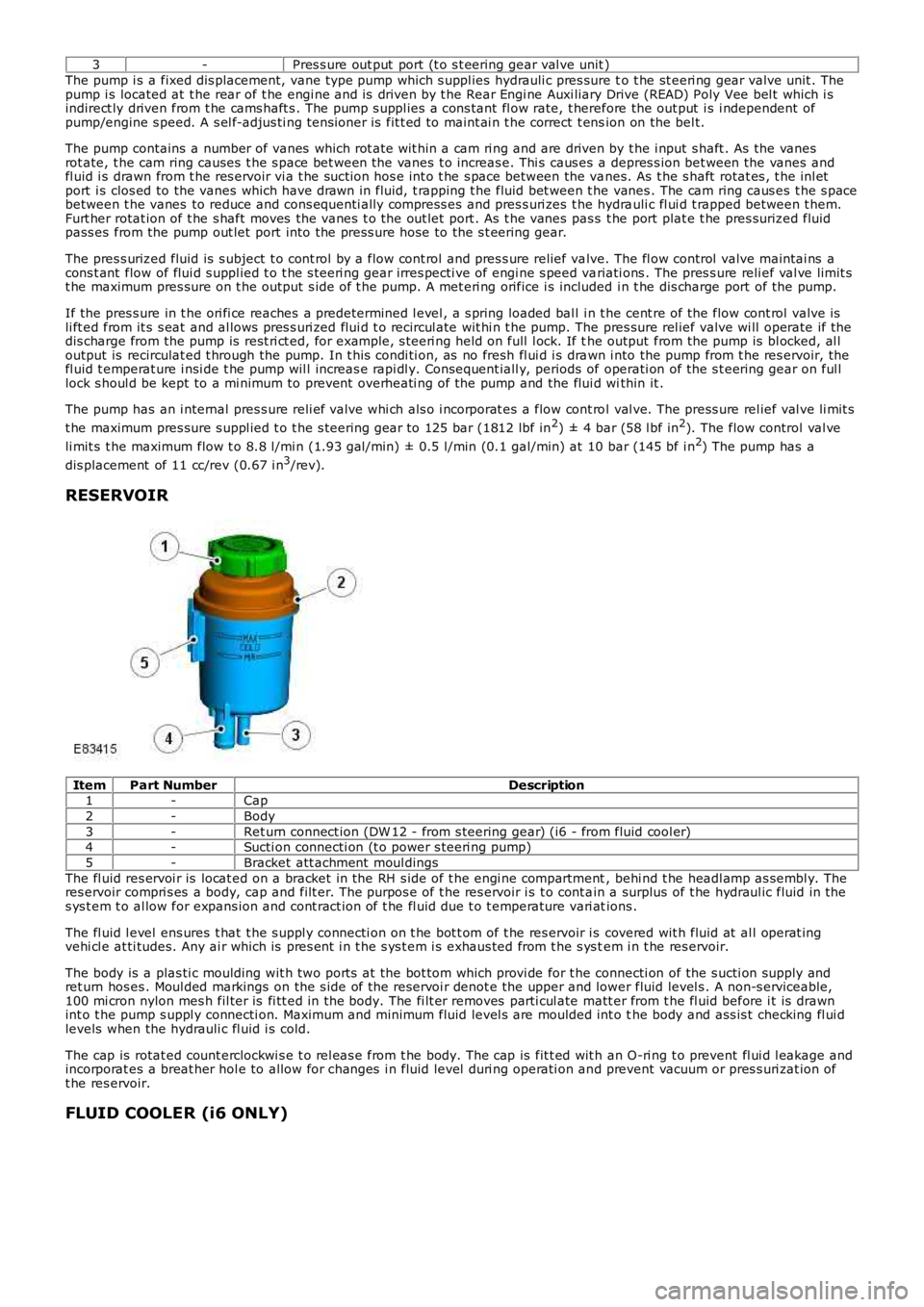
ItemPart NumberDescription1-Cap
2-Body
3-Ret urn connect ion (DW 12 - from s teering gear) (i6 - from fluid cool er)4-Sucti on connecti on (t o power s teeri ng pump)
5-Bracket att achment moul dings
The fl uid res ervoi r is locat ed on a bracket in the RH s ide of t he engi ne compartment, behi nd t he headl amp as sembl y. Theres ervoir compri s es a body, cap and filt er. The purpos e of t he res ervoir i s t o cont ain a surplus of t he hydraul ic fluid in thes ys t em t o al low for expans ion and cont ract ion of t he fl uid due t o t emperature vari ations .
The fl uid l evel ens ures t hat t he s uppl y connecti on on t he bot t om of t he res ervoir i s covered wit h fluid at al l operat ingvehi cl e at ti tudes. Any ai r which is pres ent i n t he s ys t em i s exhaus ted from t he s ys tem i n t he res ervoir.
The body is a plas ti c moulding wit h two port s at the bot tom which provi de for t he connecti on of the s ucti on supply andret urn hos es . Moul ded markings on the s ide of t he reservoi r denot e the upper and lower fluid level s . A non-s erviceable,100 mi cron nylon mes h fil ter is fi tt ed in the body. The fi lt er removes parti cul ate matt er from t he fl uid before i t is drawnint o t he pump s uppl y connecti on. Maximum and minimum fluid level s are moulded int o the body and ass is t checking fl ui dlevels when the hydrauli c fl uid i s cold.
The cap is rotat ed count erclockwi s e t o rel eas e from t he body. The cap is fit t ed wit h an O-ri ng t o prevent fl ui d l eakage andincorporat es a breat her hol e to allow for changes i n fluid level duri ng operati on and prevent vacuum or pres s uri zat ion oft he res ervoir.
FLUID COOLER (i6 ONLY)
Page 802 of 3229
Publi s hed: 11-May-2011
Engine - TD4 2.2L Diesel - Engine
Diagnosi s and Tes ti ng
Principle of Operation
For a detail ed descripti on of the 2.2L Dies el engi ne, refer t o the relevant Descri pti on and Operat ion s ect ion in t heworks hop manual .REFER to: Engine (303-01B Engine - TD4 2.2L Dies el, Des cript ion and Operat ion).
Inspection and Verification
CAUTION: Di agnos is by s ubs ti tut ion from a donor vehicle is NO T acceptabl e. Subs ti tut ion of cont rol modules doesnot guarant ee confirmat ion of a faul t, and may als o caus e addit ional fault s i n t he vehi cl e being t est ed and/or t he donorvehi cl e.
• NOTE: If the control modul e or a component i s s us pect and the vehicle remains under manufacturer warrant y, refer t o theW arranty Pol icy and Procedures manual (s ect ion B1.2), or determine i f any pri or approval programme is in operat ion, pri ort o the ins tall ati on of a new module/component.
1. Verify t he cus t omer concern. Concerns have been s eparated i nto Leaks and Noise Vibration and Harshness(NVH) for ease of us e.1.
2. Vis ually ins pect for obvious s igns of mechani cal or electrical damage.2.
Visual Inspection
MechanicalIntake air s ys tem leaks/damageFuel l eaksCoolant levelCoolant leaks.REFER to: Engine Cooli ng (303-03B Engi ne Cool ing - TD4 2.2L Di es el, Di agnos is and Tes t ing).Oi l levelOi l leaksVis i bl y damaged or worn partsLoose or mis s ing nuts or bol ts
3. If an obvious cause for an obs erved or report ed concern is found, correct t he caus e (if pos s ible) beforeproceeding t o t he next s t ep.3.
4. If t he concern is not vis uall y evi dent , verify t he s ymptom and refer t o t he Symptom Chart .4.
Symptom Charts
Symptom C hart, LeaksSymptomPossible CauseAction
External coolant leaksDamaged hos e(s )Damaged expans iont ankDamaged radi atorLeaki ngs eals /gas ket sCracked/damagedcas ings
For cool ing s ys tem checks.REFER t o: Engi ne Cool ing (303-03B Engine Cooli ng - TD42.2L Dies el, Di agnos is and Tes ti ng).
Internal cool ant leaks . Note: T hismay be indicated by theproduction of w hite smoke fromthe exhaust
Leaki ngs eals /gas ket sCracked/damagedcas ings
Check for cros s contami nat ion of cooli ng sys t em andengine oi l. Check for exhaus t gases bei ng emit tedt hrough header t ank. For addi ti onal cooling sys temchecks .REFER t o: Engi ne Cool ing (303-03B Engine Cooli ng - TD42.2L Dies el, Di agnos is and Tes ti ng).
Engine overheatsInsuffi ci ent coolantInsuffi ci ent engineoi lCooli ng s ys t empres s ure cap faultThermos t at notopeningCoolant pump failureCooli ng fan fail ure
Check for correct coolant/engi ne oil l evels . For cool ings ys tem checks.REFER t o: Engi ne Cool ing (303-03B Engine Cooli ng - TD42.2L Dies el, Di agnos is and Tes ti ng).
Engine t akes t oo l ong to reachoperat ing t emperatureThermos t at st uckopenFor cool ing s ys tem checks.REFER t o: Engi ne Cool ing (303-03B Engine Cooli ng - TD42.2L Dies el, Di agnos is and Tes ti ng).External oil l eaksGas ket sSealsHos esOi l fi lt erOi l coolerDamaged/Cracked
Cl ean and confirm t he area of t he l eak. Vis uall y check t hecondit ion of oil carryi ng component s. Check the crankcaseventi lat ion s ys tem.REFER t o: Engi ne Emis s ion Cont rol (303-08B EngineEmis si on Control - TD4 2.2L Di es el, Di agnos is andTes ti ng).
Page 911 of 3229
Coolant Flow - Open Thermostat
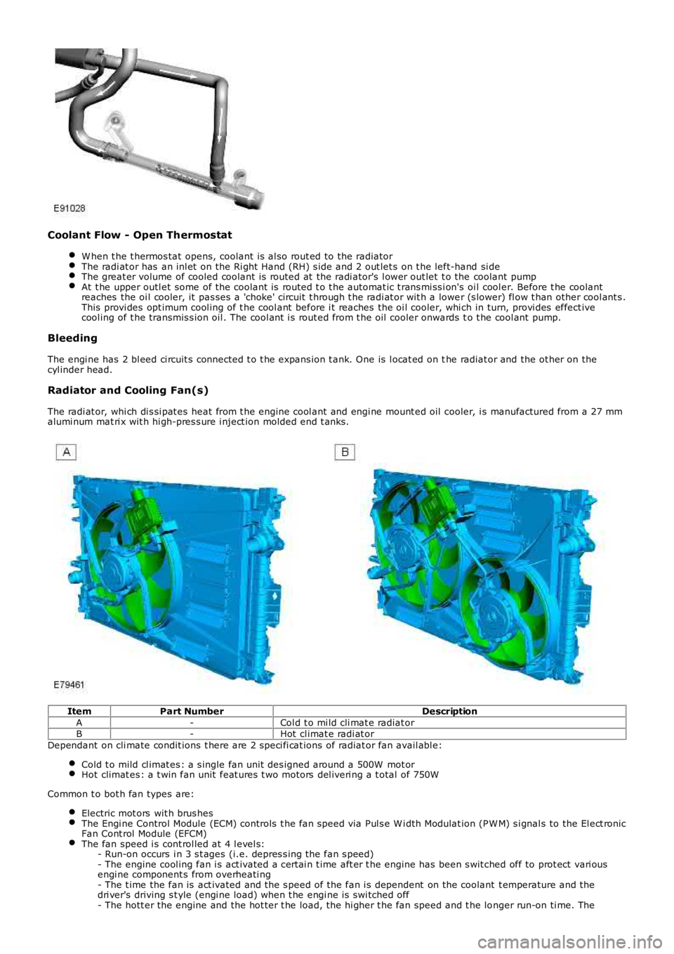
W hen t he t hermos tat opens, coolant is al so rout ed to the radiatorThe radi at or has an inl et on the Ri ght Hand (RH) s ide and 2 out let s on t he left-hand si deThe great er volume of cooled coolant is routed at the radi ator's l ower out let t o the coolant pumpAt t he upper outl et some of the coolant is routed t o t he automat ic t rans mi ss i on's oil cool er. Before t he coolantreaches the oi l cooler, it pas ses a 'choke' circuit t hrough t he radi at or wit h a lower (s lower) fl ow t han other cool ant s .This provi des opt imum cool ing of t he cool ant before i t reaches the oi l cooler, whi ch in turn, provi des effect ivecool ing of t he transmis s ion oil . The cool ant i s rout ed from t he oil cooler onwards to t he cool ant pump.
Bleeding
The engi ne has 2 bl eed ci rcuit s connected t o t he expans ion t ank. One is l ocat ed on the radiat or and the ot her on thecyl inder head.
Radiator and Cooling Fan(s)
The radi at or, whi ch di s si pat es heat from t he engine cool ant and engi ne mount ed oil cooler, i s manufactured from a 27 mmalumi num mat ri x wit h hi gh-pres s ure i nject ion molded end t anks .
ItemPart NumberDescription
A-Col d t o mi ld cli mat e radiat orB-Hot cl imat e radi at or
Dependant on cli mate condit ions t here are 2 s peci fi cat ions of radiat or fan avail abl e:
Cold t o mild cl imat es : a s ingle fan unit des igned around a 500W mot orHot climat es : a t win fan unit feat ures t wo motors del iveri ng a t otal of 750W
Common t o bot h fan types are:
Electric mot ors wit h brus hesThe Engi ne Control Module (ECM) controls t he fan speed via Pul s e W i dth Modulat ion (PW M) s i gnal s to the El ect ronicFan Cont rol Module (EFCM)The fan speed i s cont rol led at 4 l evel s:- Run-on occurs i n 3 s t ages (i.e. depres s ing the fan s peed)- The engine cool ing fan i s act ivated a cert ai n t ime aft er t he engine has been s wit ched off to prot ect vari ousengi ne component s from overheati ng- The t ime the fan is act ivated and the s peed of the fan i s dependent on the coolant t emperature and thedri ver's driving s t yle (engi ne load) when t he engi ne is swi tched off- The hott er the engine and the hot ter t he load, the hi gher t he fan speed and t he longer run-on ti me. The