2006 LAND ROVER FRELANDER 2 clock
[x] Cancel search: clockPage 18 of 3229
A clock face sys tem is somet imes us ed as an al ternat ive method of indi cat ing t he s trengt h grade. The external chamfers ora face of t he nut is marked i n a pos it ion relati ve to the appropriat e hour mark on a cl ock face to indicate the s t rengthgrade.
A dot i s used to l ocat e t he 12 o'clock posi ti on and a das h t o indi cat e t he st rengt h grade. If t he grade i s above 12, t wodots i dent ify t he 12 o'clock posi ti on.
W hen t ight eni ng a s lot ted or cas tell ated nut , never loos en it t o i nsert a s pli t pi n except where s pecified as part of anadjus tment procedure. If di fficult y is experi enced i n correct ly pos it ioning t he s lot, alt ernati ve washers or nut s s houl d bes elect ed.
W here a nut is ti ght ened to adjust or mai ntain bearing pre-l oad, t he ti ght ening procedure must be adhered to.
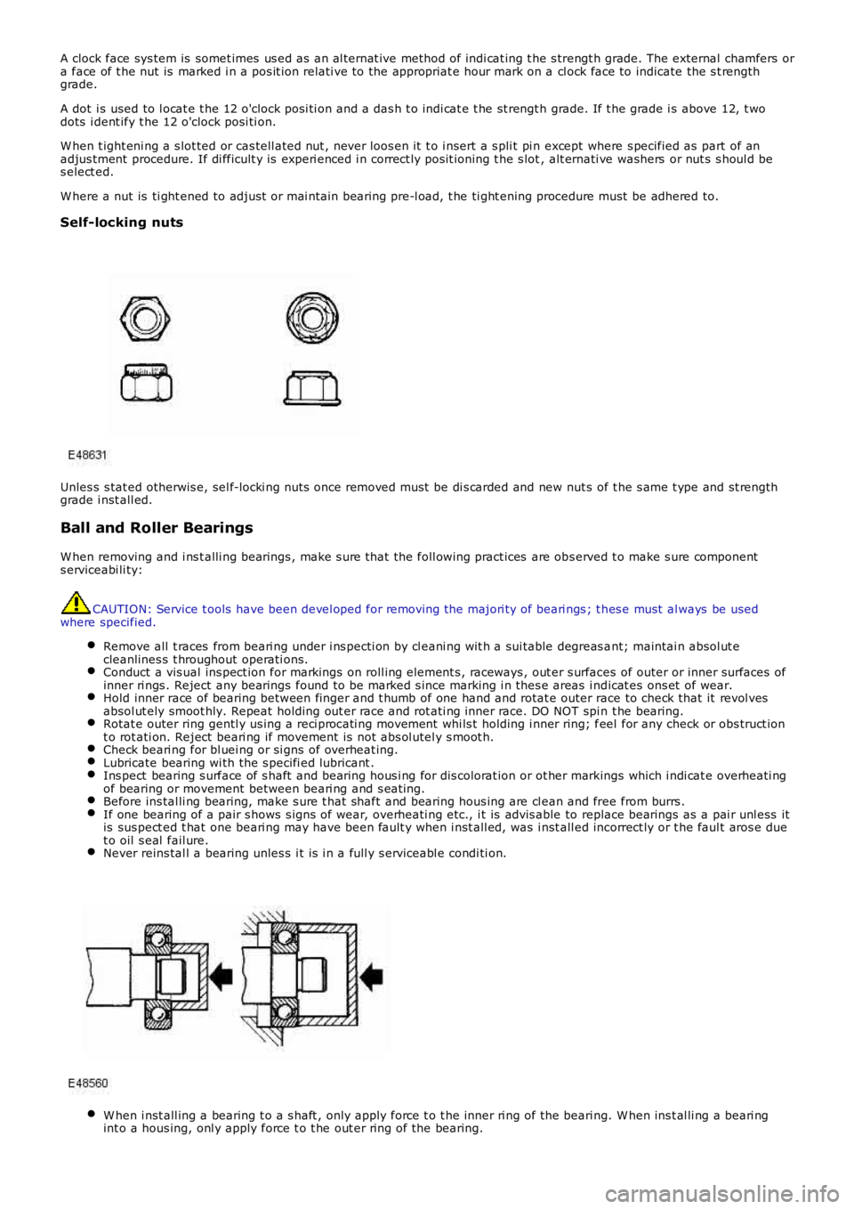
Self-locking nuts
Unles s s tat ed otherwis e, sel f-locki ng nuts once removed must be di s carded and new nut s of t he s ame t ype and st rengthgrade i nst all ed.
Ball and Roller Bearings
W hen removing and i ns t alli ng bearings , make s ure t hat the foll owing pract ices are obs erved t o make s ure components erviceabi li ty:
CAUTION: Service t ools have been devel oped for removing the majori ty of beari ngs ; t hes e must al ways be usedwhere specified.
Remove all t races from beari ng under i ns pecti on by cl eani ng wit h a sui table degreas ant; maintai n absol ut ecleanlines s t hroughout operati ons.Conduct a vis ual ins pect ion for markings on roll ing element s , raceways , out er s urfaces of outer or inner surfaces ofinner ri ngs . Reject any bearings found to be marked s ince marking i n thes e areas i ndicat es ons et of wear.Hold inner race of bearing between finger and t humb of one hand and rotat e outer race to check that it revol vesabsol ut ely smoot hly. Repeat holding out er race and rot ati ng inner race. DO NOT spi n t he bearing.Rotat e outer ring gentl y us ing a reci procati ng movement whi ls t holding i nner ring; feel for any check or obs truct iont o rot ati on. Reject beari ng if movement is not abs ol utel y s moot h.Check beari ng for bl uei ng or si gns of overheat ing.Lubricate bearing wi th the s pecifi ed lubricant .Ins pect bearing s urface of s haft and beari ng hous i ng for dis colorat ion or ot her markings which i ndi cat e overheati ngof bearing or movement between beari ng and s eat ing.Before ins tal li ng bearing, make s ure t hat shaft and bearing hous ing are cl ean and free from burrs .If one bearing of a pair s hows s igns of wear, overheati ng etc., i t is advis able to replace bearings as a pai r unl ess itis sus pect ed t hat one beari ng may have been fault y when i nst all ed, was i nst all ed incorrect ly or t he faul t aros e duet o oil s eal fail ure.Never reins tal l a bearing unles s i t is i n a full y s erviceabl e condi ti on.
W hen i nst all ing a bearing t o a s haft , only apply force t o t he inner ri ng of the beari ng. W hen ins t al li ng a beari ngint o a hous ing, onl y apply force t o t he out er ri ng of the bearing.
Page 27 of 3229
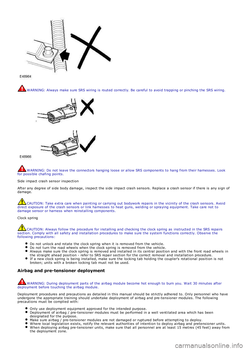
W ARNING: Always make s ure SRS wiring i s rout ed correctl y. Be careful to avoi d trapping or pinchi ng t he SRS wiring.
W ARNING: Do not leave the connect ors hanging l oos e or al low SRS component s t o hang from their harnes s es . Lookfor pos si ble chafi ng points .
Side i mpact cras h sens or ins pecti on
Aft er any degree of si de body damage, i ns pect the s i de impact cras h s ens ors . Replace a cras h s ens or i f there is any s i gn ofdamage.
CAUTION: Take ext ra care when paint ing or carryi ng out bodywork repairs in the vi ci ni ty of the cras h s ens ors . Avoi ddirect exposure of the crash sens ors or l ink harnes ses to heat guns, wel di ng or s praying equipment. Take care not t odamage s ens or or harness when reins t al li ng components .
Clock s pri ng
CAUTION: Always foll ow t he procedure for i ns t alli ng and checking t he clock s pring as ins truct ed in the SRS repairss ect ion. Comply wi th all s afety and ins tal lati on procedures to make s ure t he s yst em funct ions correct ly. Obs erve t hefol lowing precaut ions :
Do not unlock and rot ate the clock s pri ng when it i s removed from t he vehi cl e.Do not t urn t he road wheel s when the cl ock s pring i s removed from the vehicle.Always make s ure the cl ock s pri ng is removed and ins t al led i n i ts central pos it ion and wit h t he front road wheels i nt he st rai ght ahead pos it ion - refer t o SRS repair s ecti on for t he correct removal and ins tal lat ion procedure.If a new clock s pring is being ins tall ed, make sure t he locki ng t ab hol ding t he coupl er's rotat ional pos i ti on is notbroken; uni ts wit h a broken l ocking tab mus t not be us ed.
Airbag and pre-tensioner deployment
W ARNING: During deployment part s of the ai rbag modul e become hot enough to burn you. W ait 30 minut es aft erdepl oyment before t ouching the ai rbag module.
Deployment procedures and precaut ions as detai led i n thi s manual s hould be st ri ctl y adhered to. Onl y pers onnel who haveundergone the appropriate training s hould undert ake depl oyment of airbag and pre-tens ioner modul es. The followi ngprecaut ions mus t be compli ed wi th:
Only us e deployment equi pment approved for the intended purpos e.Deployment of ai rbag / pre-t ens ioner modules mus t be performed in a well vent il ated area which has beendesi gnat ed for t he purpos e.Make s ure ai rbag / pre-t ens ioner modules are not damaged or rupt ured before at tempt ing t o deploy.W here local legis lat ion exis t s, not ify the relevant aut horit ies of i ntenti on t o deploy airbag and pretens ioner uni ts .W hen deploying ai rbag pre-t ens ioner unit s, make s ure that all personnel are at l eas t 15 met res (45 feet ) away fromt he depl oyment zone.
Page 274 of 3229
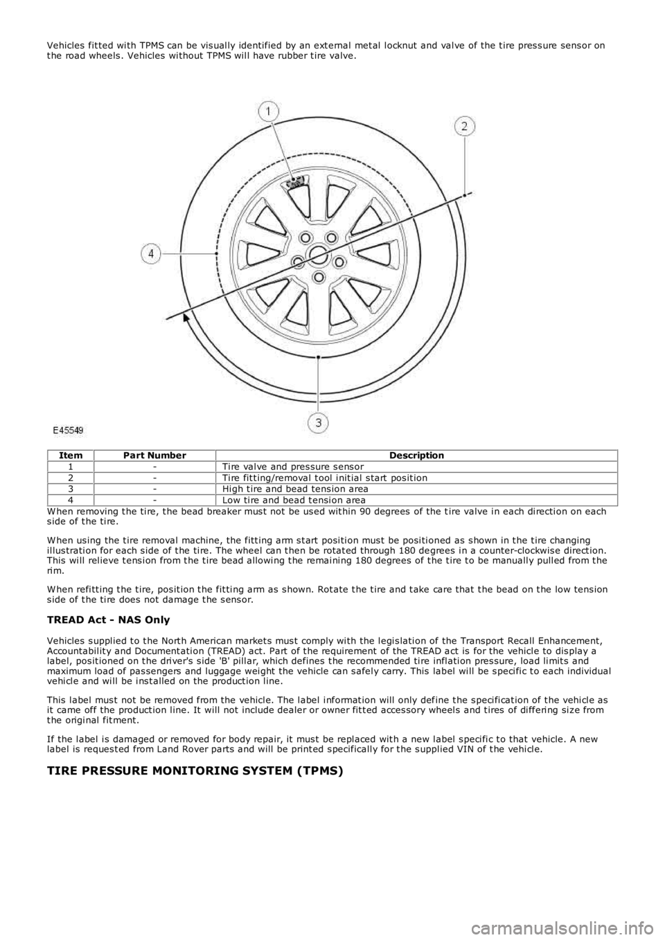
Vehicles fit ted wi th TPMS can be vis ual ly ident ified by an ext ernal met al l ocknut and val ve of the t ire pres s ure sens or ont he road wheels . Vehicles wi thout TPMS wil l have rubber t ire valve.
ItemPart NumberDescription
1-Ti re val ve and pres sure s ens or
2-Ti re fit t ing/removal t ool i nit ial s tart pos it ion3-Hi gh t ire and bead tens ion area
4-Low ti re and bead t ensi on area
W hen removing t he ti re, t he bead breaker mus t not be us ed wit hin 90 degrees of the tire valve i n each di recti on on eachs ide of t he ti re.
W hen us ing the t ire removal machine, the fit t ing arm s t art posi ti on mus t be posi ti oned as s hown in t he t ire changingil lus trati on for each s ide of t he ti re. The wheel can t hen be rotat ed through 180 degrees i n a counter-clockwis e direct ion.This wi ll rel ieve t ens i on from t he t ire bead allowi ng t he remai ni ng 180 degrees of the t ire t o be manuall y pull ed from t heri m.
W hen refi tt ing t he t ire, pos it ion t he fit ti ng arm as s hown. Rot ate t he t ire and t ake care that t he bead on t he low tens ions ide of t he ti re does not damage t he s ens or.
TREAD Act - NAS Only
Vehicles s uppl ied t o t he Nort h American market s mus t comply wi th the l egi s lati on of the Transport Recall Enhancement,Accountabil it y and Document ati on (TREAD) act. Part of t he requirement of the TREAD act is for the vehicl e to dis play alabel, pos it ioned on t he dri ver's s ide 'B' pill ar, which defines t he recommended ti re infl ati on pres sure, load li mit s andmaximum load of pas sengers and luggage wei ght the vehicle can s afel y carry. This label wi ll be s peci fi c t o each individualvehi cl e and wi ll be i ns t alled on the product ion l ine.
This l abel mus t not be removed from the vehicl e. The l abel i nformat ion will only define t he s peci fi cat ion of t he vehi cl e asit came off the product ion l ine. It will not include dealer or owner fit t ed acces sory wheel s and t ires of di fferi ng si ze fromt he origi nal fit ment.
If the l abel i s damaged or removed for body repair, it mus t be repl aced wit h a new label s peci fi c t o that vehicle. A newlabel is reques t ed from Land Rover parts and will be print ed s pecificall y for t he s uppl ied VIN of t he vehi cl e.
TIRE PRESSURE MONITORING SYSTEM (TPMS)
Page 294 of 3229
Inexperi enced off-road dri vers may benefi t from t he automat ic as s is tance of t he Terrai n Respons e s yst em and t he driverinformat ion. Experienced off-road drivers can s elect the specific programs for ext reme condit ions t o acces s cont rol over t hevehi cl e s yst ems (for example; accel erator pedal maps , t rans mis s ion s hift maps , traction s ett ings ) which are not access i bl eon vehicles wi thout Terrai n Res pons e.
Stop/St art Vehicl es - From 2010 MY
Acti vat ion of t he Terrai n Res pons e s peci al programs wi ll deact ivate the St op/St art syst em.
However, if Terrain Res pons e is acti vat ed when t he engi ne is shut down in a Stop/St art cycl e t he engi ne wil l aut omat ical lyres t art . If duri ng thi s event t he Stop/Start sys tem cannot detect the driver's occupancy, for example ei ther t he dri ver’ss afety bel t or door i s unlatched, the engine wi ll not res t art . The St op/St art s yst em will reques t t he driver t o depres s theclutch t o rest art t he engine. The dri ver wi ll be i nformed of t his by ‘RESTART REQUIRED PRESS CLUTCH’ being di spl ayed i nt he mes sage center.For addit ional informat ion, refer t o: Starti ng Sys t em (303-06C Starti ng Syst em - TD4 2.2L Di es el, Vehicles Bui lt From:01-03-2009, Descripti on and Operat ion).
TERRAIN RESPONSE ROTARY CONTROL AND MODULE
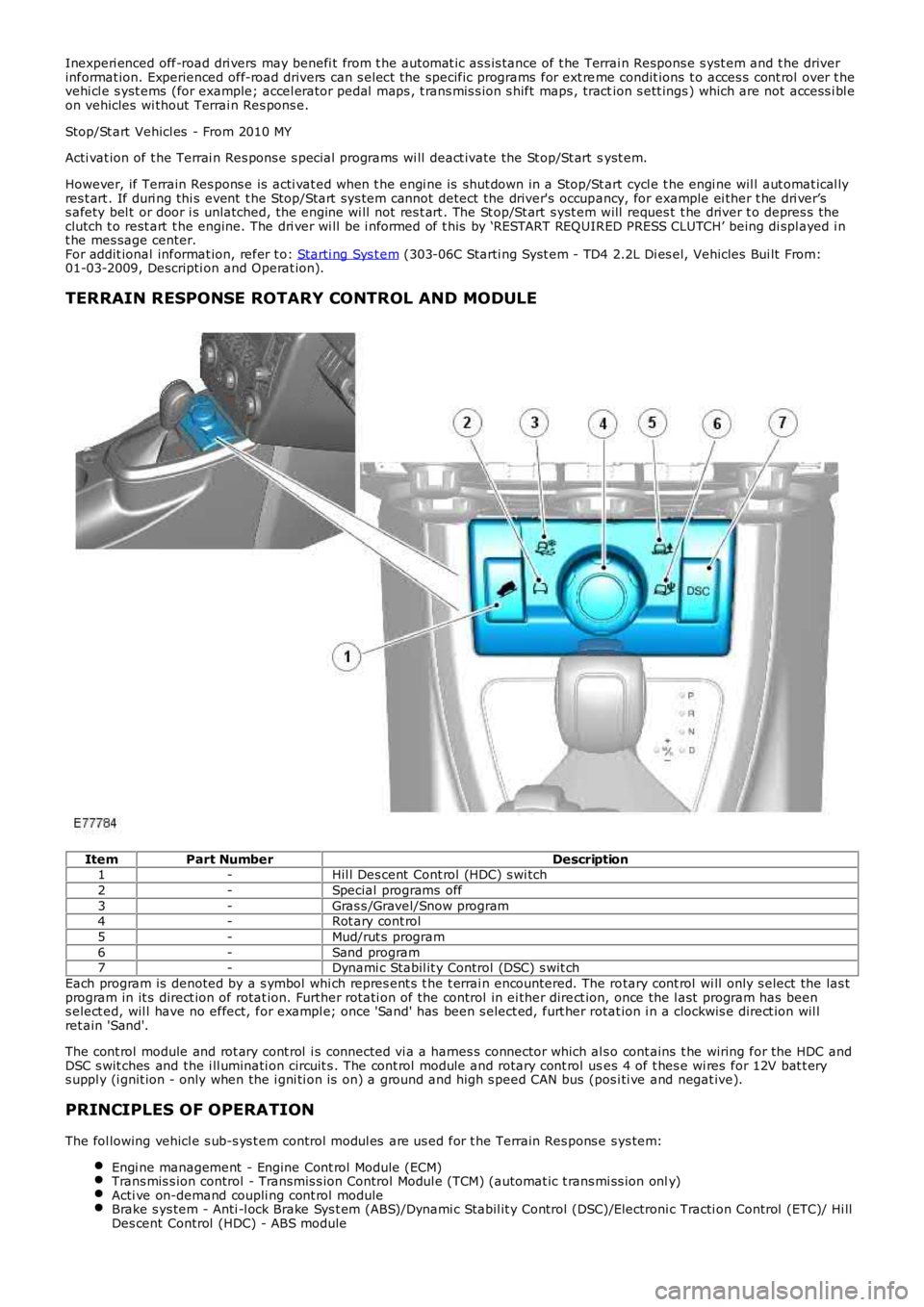
ItemPart NumberDescription1-Hil l Des cent Cont rol (HDC) s wi tch
2-Special programs off
3-Gras s /Gravel/Snow program4-Rot ary cont rol
5-Mud/rut s program
6-Sand program7-Dynami c Stabil it y Control (DSC) s wit ch
Each program is denoted by a s ymbol whi ch repres ent s t he t errai n encountered. The rotary cont rol wi ll only s elect the las tprogram in it s direct ion of rotat ion. Further rot ati on of the control in ei ther direct ion, once the l ast program has beens elect ed, wil l have no effect, for exampl e; once 'Sand' has been s elect ed, furt her rotat ion i n a clockwis e direct ion wil lret ain 'Sand'.
The cont rol module and rot ary cont rol i s connected vi a a harnes s connector which al so cont ains t he wiring for the HDC andDSC s wit ches and the i ll uminati on circuit s . The cont rol module and rotary cont rol uses 4 of t hes e wi res for 12V bat t erys uppl y (i gnit ion - only when the i gni ti on is on) a ground and high s peed CAN bus (pos i ti ve and negat ive).
PRINCIPLES OF OPERATION
The fol lowing vehicl e s ub-s ys t em control modul es are us ed for t he Terrain Res pons e sys tem:
Engi ne management - Engine Cont rol Module (ECM)Trans mis s ion control - Transmis s ion Control Modul e (TCM) (automat ic t rans mi ss ion only)Acti ve on-demand coupli ng cont rol moduleBrake s ys tem - Anti -l ock Brake Sys t em (ABS)/Dynami c Stabil it y Control (DSC)/Electroni c Tracti on Control (ETC)/ Hi llDes cent Control (HDC) - ABS module
Page 359 of 3229
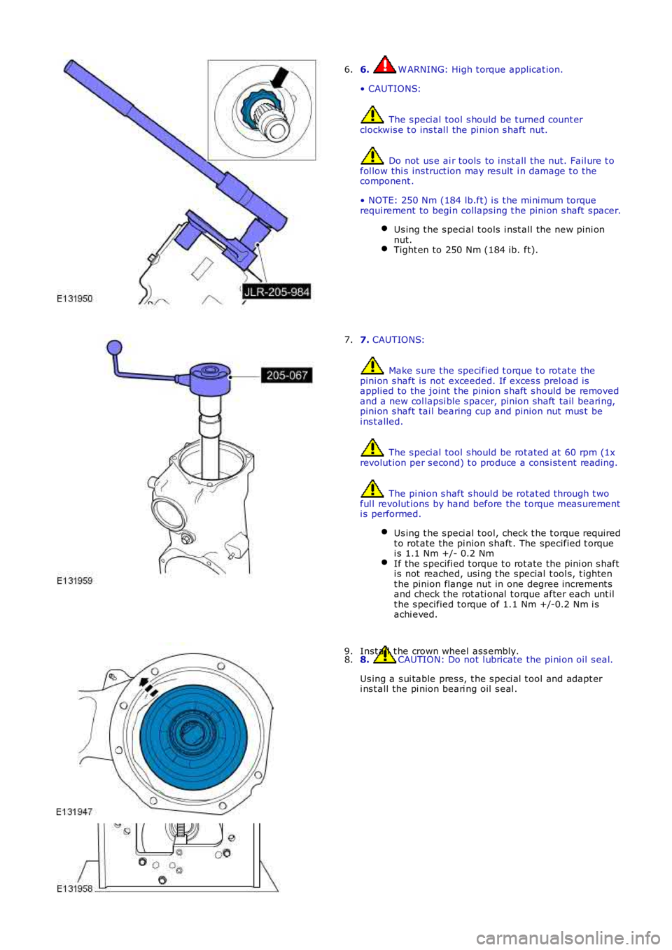
6. W ARNING: High t orque applicat ion.
• CAUTIONS:
The s peci al tool s hould be t urned count erclockwis e t o ins t al l the pi nion s haft nut.
Do not us e ai r tools to i nst all t he nut. Fail ure t ofol low thi s ins truct ion may res ult i n damage t o thecomponent .
• NOTE: 250 Nm (184 lb.ft) i s t he mi ni mum torquerequi rement to begi n collaps ing t he pini on s haft s pacer.
Us ing t he s peci al t ools i nst all t he new pini onnut.Tight en to 250 Nm (184 ib. ft).
6.
7. CAUTIONS:
Make s ure the specified t orque t o rot ate thepini on s haft is not exceeded. If exces s prel oad isapplied to the joint t he pinion s haft s hould be removedand a new col lapsi ble s pacer, pinion shaft tail beari ng,pini on s haft tai l bearing cup and pinion nut mus t bei ns t alled.
The s peci al tool s hould be rot ated at 60 rpm (1xrevolut ion per s econd) t o produce a cons i st ent reading.
The pi ni on s haft s houl d be rotat ed through t woful l revolut ions by hand before the t orque meas urementi s performed.
Us ing t he s peci al t ool, check t he t orque requiredt o rot ate the pi nion s haft . The specified t orquei s 1.1 Nm +/- 0.2 NmIf the s pecifi ed t orque t o rot ate the pi ni on s hafti s not reached, usi ng t he s pecial t ool s, t ight ent he pinion flange nut in one degree increment sand check t he rot ati onal t orque after each unt ilt he s pecified t orque of 1.1 Nm +/-0.2 Nm i sachi eved.
7.
8. CAUTION: Do not l ubricate the pi ni on oil s eal.
Us ing a s ui table pres s, t he s peci al t ool and adapt eri ns t all the pi nion beari ng oil s eal .
8.Inst all t he crown wheel ass embly.9.
Page 515 of 3229
For addit ional informat ion, refer t o:
Ins trument Clus ter (413-01 Ins t rument Clus t er, Descripti on and Operat ion),Informat ion and Mes s age Cent er (413-08 Informati on and Mes sage Cent er, Descripti on and Operat ion).
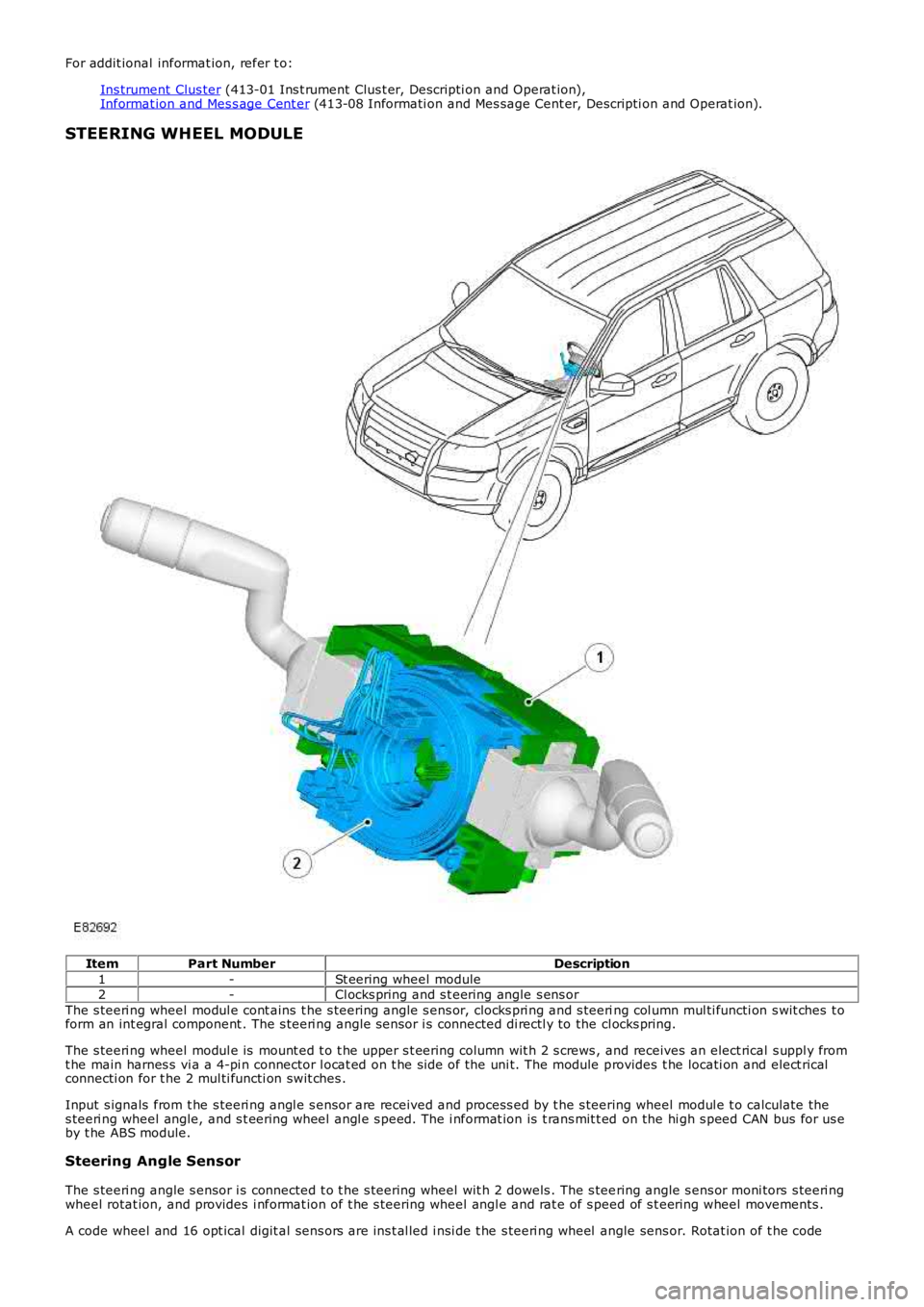
STEERING WHEEL MODULE
ItemPart NumberDescription
1-St eering wheel module2-Cl ocks pring and s t eering angle s ens or
The s teeri ng wheel modul e cont ains t he s teering angle s ens or, clocks pri ng and s teering col umn mul ti functi on s wit ches t oform an int egral component . The s teeri ng angle s ensor i s connected di rectl y to the cl ocks pring.
The s teeri ng wheel modul e is mount ed t o t he upper s t eering column wit h 2 s crews , and receives an elect rical s uppl y fromt he main harnes s vi a a 4-pi n connector l ocat ed on t he si de of the uni t. The module provides t he locati on and elect ricalconnecti on for t he 2 mul ti functi on swit ches .
Input s ignals from t he s teeri ng angl e s ensor are received and process ed by t he s teering wheel modul e t o calculate thes teeri ng wheel angle, and s t eering wheel angl e s peed. The i nformat ion is t rans mit t ed on the hi gh s peed CAN bus for us eby t he ABS module.
Steering Angle Sensor
The s teeri ng angle s ensor i s connected t o t he s teering wheel wit h 2 dowels . The s teering angle s ens or moni tors s teeri ngwheel rotat ion, and provides i nformat ion of t he s teering wheel angl e and rat e of s peed of s t eering wheel movements .
A code wheel and 16 opt ical digit al sens ors are ins t al led i nsi de t he s teeri ng wheel angle sens or. Rotat ion of t he code
Page 516 of 3229

wheel i s read by the opt ical-di git al s ens ors t o produce s teeri ng wheel rotat ional speed s ignals . The s teering angle s ens oris abl e t o meas ure a rot at ion range of +/- 720 degrees , alt hough t he s teering mechani s m wi ll only al low the s t eeringwheel t o rotat e a maxi mum of +/-540 degrees .
Signals from t he st eeri ng angl e s ens or are trans mi tt ed on t he vehicle hi gh s peed CAN bus , and received and proces sed byother s yst ems s uch as DSC. The trans mi tt ed i nformat ion i ncl udes det ails of st eering wheel angle and s t eering wheelrot ati onal s peed, along wit h s ignal i ntegri ty informati on.
If a fault occurs wi thi n t he st eeri ng angl e s ens or, a DTC wi ll be s et and s tored in t he s teering angle s ens or memory. Thes teeri ng angle s ensor faul t is al s o s tored in the ABS modul e memory that i lluminates t he appropri at e warning i ndi cat orlamps , depending on the sys tem functi ons affect ed (DSC/ETC, ABS, EBA/EBD, HDC). A warni ng chi me i s als o s ounded t oalert the driver to the fault condi ti on.
For vehicles ins tall ed wit h a high-l ine i ns t rument clus ter, a mes s age is di spl ayed in t he mes sage center, onl y if t he faul taffect s t he HDC funct ion.
For addit ional informat ion, refer t o:
Ins trument Clus ter (413-01 Ins t rument Clus t er, Descripti on and Operat ion),Informat ion and Mes s age Cent er (413-08 Informati on and Mes sage Cent er, Descripti on and Operat ion).
The s teeri ng angle s ensor and ABS modul e are abl e t o be i nt errogat ed us ing t he Land Rover approved diagnos t icequi pment.
Clockspring
The clocks pri ng is a rot ary coupling that provides t he electrical connect ion bet ween the fixed s t eering wheel module, andt he st eeri ng wheel mount ed cont rols and Supplement al Res t raint Sys tem (SRS) dri ver's ai rbag.
A colored indicator i s provided wi thi n the cl ocks pring and is vis i bl e t hrough a t rans parent pers pex cover when the s t eeringwheel i s removed, and t he st eeri ng angl e s ens or is aligned t o t he cent ral posi ti on. The indicator makes s ure t he s teeringangl e s ensor and s t eering s ys tem are correct ly al igned fol lowi ng repairs t o the st eeri ng mechanis m.
Service Information
Before s eparat ing the s t eering component s from the connect ing s t eering column, t he clocks pri ng mus t be ali gned to thecent er pos i ti on (i ndi cat or vi s ible) and t he wheels point ing s t raight ahead. The clockspring i s ret ained i n the cent ralposi ti on wit h a locki ng s crew.
INSTRUMENT CLUSTER INDICATOR LAMPS
Page 541 of 3229
3-Pres s ure out put port (t o s t eering gear val ve unit )
The pump i s a fixed dis placement, vane type pump which s uppl ies hydrauli c pres sure to t he st eeri ng gear valve unit . Thepump i s located at t he rear of t he engi ne and is driven by t he Rear Engi ne Auxi liary Drive (READ) Poly Vee bel t which i sindirect ly driven from t he cams haft s . The pump s uppl ies a cons tant fl ow rate, t herefore the out put i s i ndependent ofpump/engine s peed. A s el f-adjus ti ng tens ioner is fit t ed to maint ai n t he correct t ension on the bel t.
The pump contains a number of vanes which rot ate wit hin a cam ri ng and are driven by t he i nput s haft . As the vanesrot ate, t he cam ring causes t he s pace bet ween the vanes t o increas e. Thi s caus es a depres s ion bet ween the vanes andfl uid i s drawn from t he res ervoir vi a t he suct ion hos e int o t he s pace between the vanes. As t he s haft rotat es , t he inl etport i s clos ed to the vanes which have drawn in fluid, t rapping t he fluid bet ween t he vanes . The cam ring caus es t he s pacebetween t he vanes to reduce and cons equenti ally compress es and pres s uri zes t he hydrauli c fl ui d t rapped between t hem.Furt her rotat ion of t he s haft moves the vanes t o the out let port . As t he vanes pas s t he port plat e t he pres surized fluidpass es from the pump out let port into the press ure hose to the s t eering gear.
The pres s urized fluid is s ubject t o cont rol by a flow cont rol and pres s ure relief valve. The fl ow control valve maintai ns acons t ant flow of flui d s uppl ied t o t he s teeri ng gear irres pecti ve of engi ne s peed variati ons . The pres s ure reli ef val ve limit st he maximum pres sure on t he output s ide of t he pump. A met eri ng orifice i s included i n t he dis charge port of the pump.
If the pres s ure in t he ori fi ce reaches a predetermined l evel , a s pring loaded bal l in t he cent re of the flow cont rol valve isli ft ed from it s s eat and al lows pres s uri zed flui d t o recircul ate wit hi n t he pump. The pres sure rel ief valve wi ll operate if t hedis charge from the pump is rest ri ct ed, for example, s teeri ng held on full l ock. If the output from the pump is bl ocked, al loutput is recirculat ed t hrough the pump. In t his condi ti on, as no fresh fl ui d i s drawn i nto the pump from t he res ervoir, thefl uid t emperat ure i nsi de t he pump wil l increas e rapi dl y. Cons equent iall y, periods of operati on of the s t eering gear on ful llock s houl d be kept to a mi nimum to prevent overheati ng of the pump and the flui d within it .
The pump has an i nternal pres s ure reli ef valve whi ch als o i ncorporat es a flow cont rol val ve. The press ure rel ief val ve li mit s
t he maximum pres sure s uppl ied t o t he s teering gear to 125 bar (1812 lbf in2) ± 4 bar (58 l bf in2). The flow control val ve
li mit s t he maximum flow t o 8.8 l/mi n (1.93 gal/min) ± 0.5 l/min (0.1 gal/min) at 10 bar (145 bf i n2) The pump has a
dis placement of 11 cc/rev (0.67 i n3/rev).
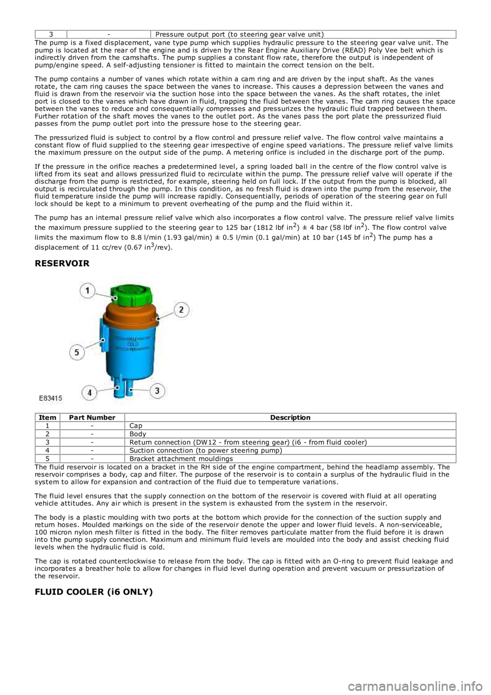
RESERVOIR
ItemPart NumberDescription1-Cap
2-Body
3-Ret urn connect ion (DW 12 - from s teering gear) (i6 - from fluid cool er)4-Sucti on connecti on (t o power s teeri ng pump)
5-Bracket att achment moul dings
The fl uid res ervoi r is locat ed on a bracket in the RH s ide of t he engi ne compartment, behi nd t he headl amp as sembl y. Theres ervoir compri s es a body, cap and filt er. The purpos e of t he res ervoir i s t o cont ain a surplus of t he hydraul ic fluid in thes ys t em t o al low for expans ion and cont ract ion of t he fl uid due t o t emperature vari ations .
The fl uid l evel ens ures t hat t he s uppl y connecti on on t he bot t om of t he res ervoir i s covered wit h fluid at al l operat ingvehi cl e at ti tudes. Any ai r which is pres ent i n t he s ys t em i s exhaus ted from t he s ys tem i n t he res ervoir.
The body is a plas ti c moulding wit h two port s at the bot tom which provi de for t he connecti on of the s ucti on supply andret urn hos es . Moul ded markings on the s ide of t he reservoi r denot e the upper and lower fluid level s . A non-s erviceable,100 mi cron nylon mes h fil ter is fi tt ed in the body. The fi lt er removes parti cul ate matt er from t he fl uid before i t is drawnint o t he pump s uppl y connecti on. Maximum and minimum fluid level s are moulded int o the body and ass is t checking fl ui dlevels when the hydrauli c fl uid i s cold.
The cap is rotat ed count erclockwi s e t o rel eas e from t he body. The cap is fit t ed wit h an O-ri ng t o prevent fl ui d l eakage andincorporat es a breat her hol e to allow for changes i n fluid level duri ng operati on and prevent vacuum or pres s uri zat ion oft he res ervoir.
FLUID COOLER (i6 ONLY)