2006 LAND ROVER FRELANDER 2 clock
[x] Cancel search: clockPage 1662 of 3229
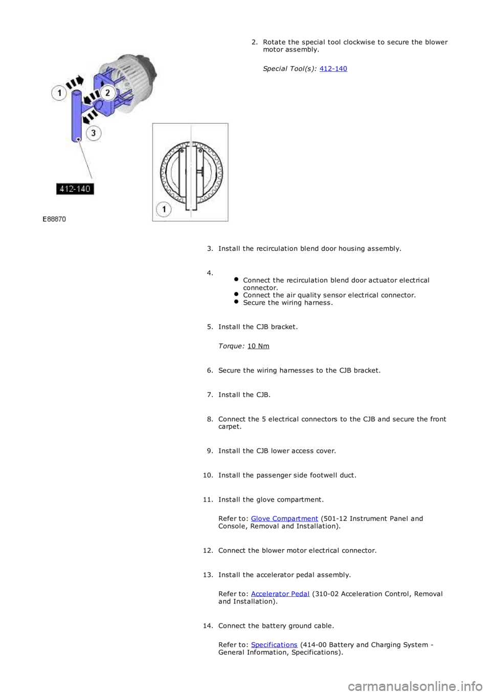
Rotat e t he s pecial t ool clockwis e t o s ecure t he blower
mot or as s embly.
Speci al Tool (s ): 412-140 2.
Inst all t he recircul at ion bl end door hous ing as s embl y.
3.
Connect t he recircul ati on blend door act uat or el ect ri cal
connector. Connect t he air qualit y s ensor el ect ri cal connector.
Secure t he wiring harnes s .4.
Inst all t he CJB bracket .
T orque: 10 Nm 5.
Secure t he wiring harnes s es to the CJB bracket.
6.
Inst all t he CJB.
7.
Connect t he 5 elect rical connectors to the CJB and s ecure t he front
carpet.
8.
Inst all t he CJB lower acces s cover.
9.
Inst all t he pas s enger s ide footwel l duct .
10.
Inst all t he glove compartment .
Refer t o: Glove Compart ment (501-12 Ins trument Panel and
Consol e, Removal and Ins t al lat ion).
11.
Connect t he blower mot or el ect ri cal connector.
12.
Inst all t he accelerat or pedal as sembl y.
Refer t o: Accelerat or Pedal (310-02 Accelerati on Cont rol , Removal
and Inst all at ion).
13.
Connect t he batt ery ground cable.
Refer t o: Specificati ons (414-00 Bat tery and Charging Sys tem -
General Informat ion, Specificati ons).
14.
Page 1668 of 3229
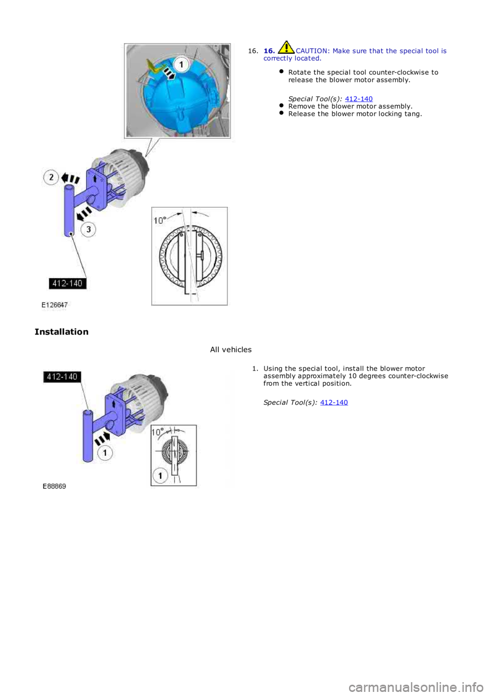
16. CAUTION: Make s ure t hat the special tool is
correct ly l ocat ed.
Rotat e t he s pecial t ool counter-clockwi s e t o
rel ease the bl ower mot or ass embl y.
Speci al Tool (s ): 412-140 Remove t he blower motor as s embly.
Releas e t he blower motor l ocking tang.16.
Installation All vehicles Us ing t he s peci al t ool, i ns t all the bl ower motor
as sembl y approximat ely 10 degrees count er-clockwi s e
from the verti cal posi ti on.
Speci al Tool (s ): 412-140 1.
Page 1669 of 3229
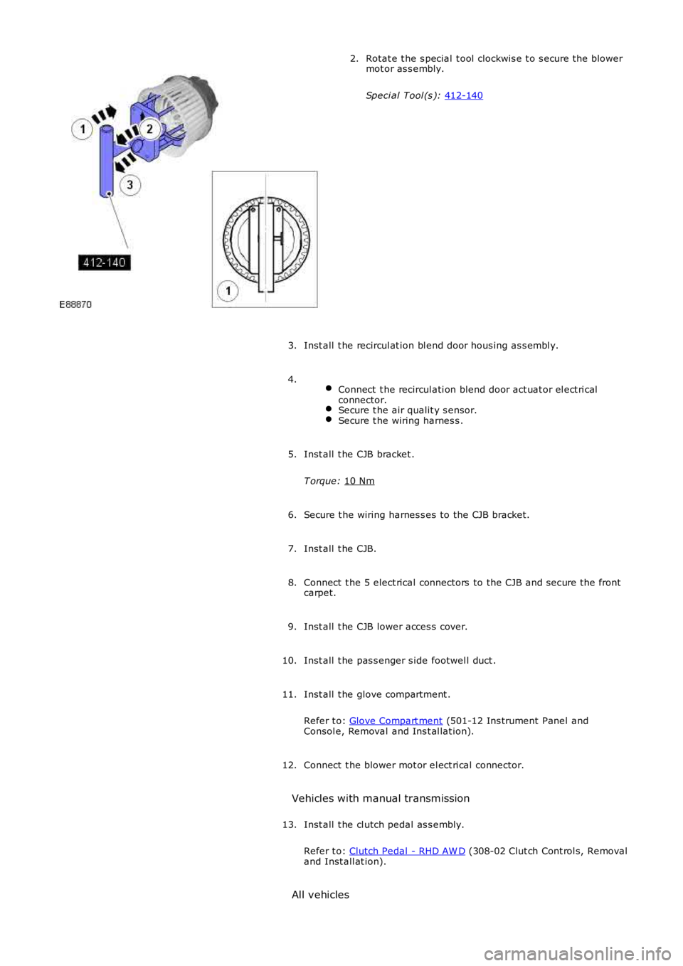
Rotat e t he s pecial t ool clockwis e t o s ecure t he blower
mot or as s embly.
Speci al Tool (s ): 412-140 2.
Inst all t he recircul at ion bl end door hous ing as s embl y.
3.
Connect t he recircul ati on blend door act uat or el ect ri cal
connector. Secure t he air qualit y s ensor.
Secure t he wiring harnes s .4.
Inst all t he CJB bracket .
T orque: 10 Nm 5.
Secure t he wiring harnes s es to the CJB bracket.
6.
Inst all t he CJB.
7.
Connect t he 5 elect rical connectors to the CJB and s ecure t he front
carpet.
8.
Inst all t he CJB lower acces s cover.
9.
Inst all t he pas s enger s ide footwel l duct .
10.
Inst all t he glove compartment .
Refer t o: Glove Compart ment (501-12 Ins trument Panel and
Consol e, Removal and Ins t al lat ion).
11.
Connect t he blower mot or el ect ri cal connector.
12.
Vehicles with manual transmission Inst all t he cl utch pedal as s embly.
Refer t o: Clutch Pedal - RHD AW D (308-02 Clut ch Cont rol s, Removal
and Inst all at ion).
13.
All vehicles
Page 1718 of 3229
Publi s hed: 11-May-2011
Climate Control - Heater Core and Evaporator Core Housing
Removal and Inst all ati on
Removal
Make t he SRS s ys t em s afe.1.
Remove t he ins trument panel.
Refer t o: Ins trument Panel - TD4 2.2L Dies el (501-12 Inst rumentPanel and Cons ole, Removal and Inst all at ion).Refer t o: Ins trument Panel - I6 3.2L Pet rol (501-12 Ins t rument Paneland Consol e, Removal and Ins t al lat ion).
2.
Remove t he cl ocks pri ng.
Refer t o: Clocks pri ng (501-20B Supplement al Res t raint Sys tem,Removal and Ins tall ati on).
3.
Remove t he ins trument cl ust er.
Refer t o: Ins trument Clus ter (413-01 Ins t rument Clus t er, Removaland Inst all at ion).
4.
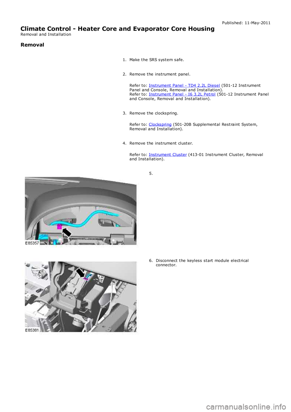
5.
Di sconnect t he keyl es s s t art module el ect ri calconnector.6.
Page 1726 of 3229
Inst all t he glove compartment .
Refer t o: Glove Compart ment (501-12 Ins trument Panel andConsol e, Removal and Ins t al lat ion).
10.
Inst all t he pas s enger s ide ins trument panel end trim panel .11.
Secure t he wiring harnes s s upport bracket .12.
Inst all t he cl imat e control as s embly.13.
Inst all t he audi o unit .14.
Inst all t he cent er speaker.15.
Inst all t he video dis play.
Refer t o: Video Dis play (415-01 Informati on and Entert ainmentSyst em, Removal and Ins tall ati on).
16.
Inst all both ins trument panel s peakers .17.
Inst all both upper t rim panels .18.
Connect t he in-vehi cl e t emperature s ens or electrical connect or.19.
Connect t he keyl es s s t art module elect rical connect or.20.
Inst all t he ins trument cl ust er.
Refer t o: Ins trument Clus ter (413-01 Ins t rument Clus t er, Removaland Inst all at ion).
21.
Inst all t he cl ocks pri ng.
Refer t o: Clocks pri ng (501-20B Supplement al Res t raint Sys tem,Removal and Ins tall ati on).
22.
Inst all t he ins trument panel.
Refer t o: Ins trument Panel - TD4 2.2L Dies el (501-12 Inst rumentPanel and Cons ole, Removal and Inst all at ion).Refer t o: Ins trument Panel - I6 3.2L Pet rol (501-12 Ins t rument Paneland Consol e, Removal and Ins t al lat ion).
23.
Connect t he batt ery ground cable.
Refer t o: Specificati ons (414-00 Bat tery and Charging Sys tem -General Informat ion, Specificati ons).
24.
Return t he s teeri ng col umn t o i ts original posi ti on.25.
Page 1784 of 3229
Publi s hed: 11-May-2011
Horn - Horn
Diagnosi s and Tes ti ng
Principles of Operation
For a detail ed descripti on of the horn s yst em, refer to the relevant Des cri pt ion and Operati on s ect ion i n t he works hopmanual.REFER to: Horn (413-06 Horn, Descripti on and Operat ion).
Inspection and Verification
CAUTION: Di agnos is by s ubs ti tut ion from a donor vehicle is NO T acceptabl e. Subs ti tut ion of cont rol modules doesnot guarant ee confirmat ion of a faul t, and may als o caus e addit ional fault s i n t he vehi cl e being t est ed and/or t he donorvehi cl e.
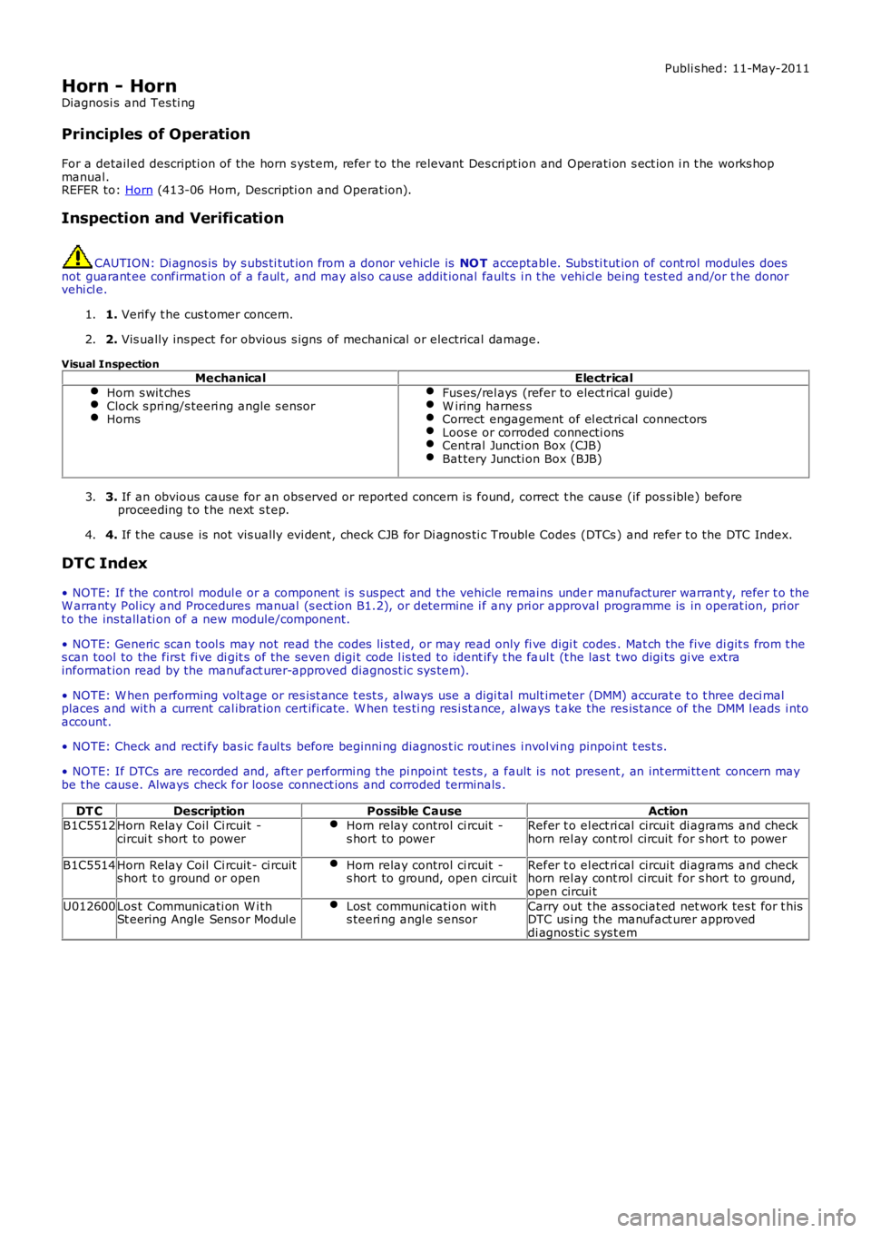
1. Verify t he cus t omer concern.1.
2. Vis ually ins pect for obvious s igns of mechani cal or electrical damage.2.
Visual InspectionMechanicalElectrical
Horn s wit chesClock s pri ng/s teeri ng angle s ensorHorns
Fus es/rel ays (refer to elect rical guide)W iring harnes sCorrect engagement of el ect ri cal connect orsLoos e or corroded connecti onsCent ral Juncti on Box (CJB)Bat tery Juncti on Box (BJB)
3. If an obvious cause for an obs erved or report ed concern is found, correct t he caus e (if pos s ible) beforeproceeding t o t he next s t ep.3.
4. If t he caus e is not vis ually evi dent , check CJB for Di agnos ti c Trouble Codes (DTCs ) and refer t o the DTC Index.4.
DTC Index
• NOTE: If the control modul e or a component i s s us pect and the vehicle remains under manufacturer warrant y, refer t o theW arranty Pol icy and Procedures manual (s ect ion B1.2), or determine i f any pri or approval programme is in operat ion, pri ort o the ins tall ati on of a new module/component.
• NOTE: Generic scan t ool s may not read the codes li st ed, or may read only fi ve digit codes . Mat ch the five di git s from t hes can tool to the firs t fi ve di git s of the seven digi t code l is ted to ident ify t he faul t (t he las t t wo digi ts gi ve ext rainformat ion read by the manufact urer-approved diagnost ic s ys tem).
• NOTE: W hen performing volt age or res is t ance t est s , always use a digi tal mult imeter (DMM) accurat e t o t hree deci malplaces and wit h a current cal ibrat ion cert ificate. W hen tes ti ng res i st ance, always take the res is tance of the DMM l eads i ntoaccount.
• NOTE: Check and recti fy bas ic faul ts before beginni ng diagnos t ic rout ines i nvol vi ng pinpoint t es t s.
• NOTE: If DTCs are recorded and, aft er performi ng the pi npoi nt tes ts , a fault is not present , an int ermi tt ent concern maybe t he caus e. Always check for loose connect ions and corroded terminals .
DT CDescriptionPossible CauseActionB1C5512Horn Relay Coil Ci rcuit -circui t s hort to powerHorn relay control ci rcuit -s hort to powerRefer t o el ect ri cal circui t di agrams and checkhorn rel ay cont rol circuit for s hort to power
B1C5514Horn Relay Coil Ci rcuit - ci rcuits hort t o ground or openHorn relay control ci rcuit -s hort to ground, open circui tRefer t o el ect ri cal circui t di agrams and checkhorn rel ay cont rol circuit for s hort to ground,open circui t
U012600Los t Communicati on W i thSt eering Angle Sens or Modul eLos t communicati on wit hs teeri ng angl e s ensorCarry out t he ass ociat ed net work tes t for t hisDTC us i ng the manufact urer approveddi agnos ti c s ys t em
Page 1795 of 3229
The current vehicle operat ing mode, s hown in parenthes is above, i s dis played in the odomet er for 5 s econds when t hevehi cl e first ent ers power mode 6.
• NOTE: 'Nor' is only di s pl ayed in t he Odometer when t he vehicle operat ing mode is changed t o normal from any of theother vehi cle operat ing modes . Under al l ot her condit ions , 'Nor' is not di spl ayed.
The vehi cl e operat ing mode can be changed us i ng the Land Rover approved di agnos ti c sys t em.
Gear Position
The gear pos it ion i ndicat or s hows the current aut omati c t ransmis s ion s elector l ever posi ti on. During normal operat ion thedis play wi ll s how P (park), R (revers e), N (neutral) and D (drive). W hen the t rans mis s ion is operat ed in 'CommandShi ft ™'mode, the odomet er di spl ays the current ly sel ect ed manual gear; 1, 2, 3, 4, 5 or 6.
In the event of eit her a CAN bus fai lure, or if t he TCM det ect s a t rans mi ss i on overheat s it uati on, t he odometer wi ll dis playt he let ter 'E' in the s ame area of t he dis play as t he 'CommandShift™' s elected gear informat ion.
Supplemental Restrain System Warning Indicator
If the i nst rument clus ter det ect s the Supplement al Res t raint Sys tem (SRS) warni ng indicator has fai led, t he mes sage 'SrS'wil l be dis played in the odomet er and a DTC s tored. The DTC can be ret rieved from the ins trument cl us t er us i ng the LandRover approved diagnost ic sys tem.
Service Interval Indicator
The Service Interval Indi cat or (SII) i nforms t he driver when t he next vehicle servi ce is due. The ins t rument clus ter monit orst he dis tance t he vehi cl e has travel ed and t he ti me el aps ed s ince t he las t s ervice.
If vehicle dis tance is the t rigger for the SII, 'SERVICE' will be di s pl ayed in t he odometer accompanied by a dis tancequal ifier (ei ther 'MILES' or 'KM' dependi ng on t he ins trument cl ust er s pecificati on). A di st ance counter wi ll als o be di s pl ayedin the t op Ri ght Hand (RH) corner of t he odometer. If t he point at which a servi ce is requi red is pas sed, t he count er wi lldis play a negat ive value. W hen acti vat ed, t he SII is di spl ayed for 5 s econds when t he vehi cl e enters power mode 6.
If ti me i s the trigger for the SII, 'SERVICE' wil l be di s pl ayed in t he odometer accompanied by a clock symbol . A count er willals o be di spl ayed i n t he t op RH corner of the odomet er. If t he point at which a s ervice is required is pas s ed, t he count erwil l dis play a negati ve val ue. Agai n, when act ivated t he SII is dis played for 5 s econds when t he vehi cl e enters power mode6.
If bot h t he dis tance and t ime triggers are acti vat ed, t he SII wil l di s pl ay the di s tance informat ion for 5 s econds, foll owedby t he ti me i nformati on for 5 s econds .
W hen a service has been carri ed out , t he SII wi ll need t o be re-s et. This can be done us ing t he Land Rover approveddiagnost ic s ys tem or foll owing a manual re-s et procedure. The manual re-s et mode is ent ered by carrying out the foll owingrout ine:
Pres s and hold the t ri p res et butt on wi th the vehicle st ati onary and in a power mode les s t han 6.W hi le holdi ng the trip res et but ton, enter t he vehi cl e int o power mode 6.Releas e the trip res et but ton wit hi n 10 s econds of entering power mode 6.
If the manual re-set mode has been s ucces s full y entered 'dISt ' or 'DATE' wi ll be di spl ayed i n t he odomet er, dependi ng onwhich t ri gger has been acti vat ed.
To clear the 'dISt ' trigger pres s, and hold the t rip reset but ton for more than 5 s econds wit hi n 10 s econds of entering t hemanual re-s et mode. If s ucces s ful, 'RESET' wil l be dis played in the odometer for 5 seconds. If t he dat e t ri gger has notbeen act ivated 'END' wil l t hen be dis played i n t he odomet er.
• NOTE: The dis t ance t ri gger wi ll not res et if t he dis t ance t he vehi cle has t raveled i s les s t han 20% of t he next s ervi ceint erval val ue.
If the dat e trigger has been act ivated, 'DATE' wil l be dis played in t he odometer. To clear the t ri gger, pres s and hold t het rip res et but t on for more t han 5 s econds wit hin 10 s econds of 'DATE' being di s pl ayed. If succes s ful , 'RESET' wi ll bedis played wit hin the odomet er for 5 s econds fol lowed by 'END'. The odomet er wil l now exit re-s et mode.
AMBIENT AIR TEMPERATURE
The ins t rument clus ter can dis play t he ambient air t emperature readi ng in ei ther degrees Cels ius or Fahrenhei t. Theambient air t emperat ure s ignal ori gi nat es i n the ambient air t emperature s ens or. The s ens or i s a Negati ve TemperatureCoefficient (NTC) t hermi st or, and i s mounted i n t he LH door mirror. A t emperature value i s cal cul ated by t he ECM andbroadcas t over the hi gh speed CAN bus to t he i ns t rument clus ter.
If the t emperat ure value fall s bel ow 4ºC (39ºF) t he mes sage center wi ll flas h the low ambi ent ai r temperat ure icon 5t imes . Thi s i s accompanied by a chime from the i nst rument clus t er s ounder. The low ambient air t emperature icon wi ll berepeated if t he ambient air t emperature ri s es above 6ºC (43ºF) t hen drops below 4ºC (39ºF) again or a new ignit ion cycleis st art ed.
Page 1827 of 3229
Publi s hed: 11-May-2011
Battery, Mounting and Cables -
General SpecificationItemSpecification
Battery - All models:
TypeExide H7Capaci ty80Ah/700CCA
Res erve capacit y125 minutes
Battery Disconnect/C onnect
CAUTION: The vehicle s t atus and batt ery condit ion mus t be es t abl is hed before att empti ng bat t erydis connect/connect . Reference mus t be t hen made t o t he fol lowing table to es t abl is h t he rel evant procedure t o befol lowed.
• NOTE: Vehicles fit ted wit h a fuel fired boos t er heat er will requi re a 5 mi nute wait before tel es t art funct ion wi ll operate.Cycl e t he ignit ion off->on->off. W ai t 5 mi nutes t o all ow fuel fired boos t er heat er to s t ore vehicle confi gurati onparamet ers .
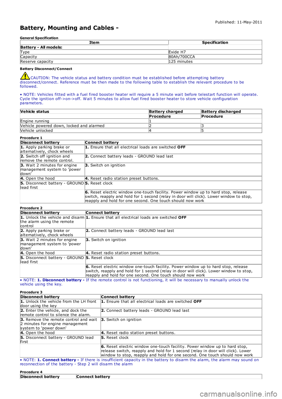
Vehicle statusBattery chargedBattery discharged
ProcedureProcedure
Engine runni ng1Vehicle powered down, l ocked and alarmed23
Vehicle unl ocked45
Procedure 1
Disconnect batteryConnect battery1. Apply parki ng brake oralt ernat ively, chock wheels1. Ens ure that all el ect ri cal loads are s wit ched O FF
2. Swit ch off i gni ti on andremove the remote cont rol.2. Connect bat t ery l eads - GROUND lead l ast
3. W ai t 2 mi nut es for enginemanagement sys tem t o 'powerdown'
3. Swit ch on ignit ion
4. Open t he hood4. Reset radi o s tat ion preset but tons .
5. Dis connect batt ery - GROUNDl ead firs t5. Reset clock
6. Reset elect ric window one-t ouch facili ty. Power window up t o hard s top, rel eas es wit ch, reapply and hol d for 1 s econd (relay i n door wil l cl ick). Lower window t o s top,reapply and hold for one s econd. One t ouch s hould now work
Procedure 2
Disconnect batteryConnect battery
1. Unlock t he vehi cl e and dis armt he alarm us ing t he remotecont rol
1. Ensure t hat al l el ect ri cal l oads are s wit ched OFF
2. Apply parki ng brake oralt ernat ively, chock wheels2. Connect batt ery l eads - GROUND l ead las t
3. W ai t 2 mi nut es for enginemanagement sys tem t o 'powerdown'
3. Swit ch on i gni ti on
4. Open t he hood4. Res et radio s t ati on pres et but tons .
5. Dis connect batt ery - GROUNDl ead firs t5. Res et cl ock
6. Res et el ect ri c window one-touch facil it y. Power window up to hard s top, rel eases wit ch, reappl y and hold for 1 s econd (rel ay in door wil l cl ick). Lower window t o s top,reapply and hol d for one s econd. One t ouch should now work
• NOTE: 1. Disconnect battery - If the remot e cont rol is not funct ioning, it will be necess ary to manual ly unlock thevehi cl e us ing t he key.
Procedure 3
Disconnect batteryConnect battery1. Unlock t he vehi cl e from the LH frontdoor us i ng the key1. Ens ure t hat al l electrical l oads are s wi tched OFF
2. Enter t he vehi cl e, and dock t heremote control to si lence the al arm.2. Connect batt ery leads - GROUND l ead las t
3. Remove t he remot e cont rol and wai t2 minutes for engi ne managements yst em to 'power down'
3. Swi tch on i gni ti on
4. Open t he hood4. Res et radio st ati on pres et but t ons .
5. Dis connect batt ery - GROUND leadfirst5. Res et cl ock
6. Res et el ect ri c wi ndow one-touch facil it y. Power wi ndow up to hard s t op,release s wit ch, reapply and hol d for 1 second (relay i n door wil l cl ick). Lowerwi ndow to s top, reapply and hold for one s econd. One t ouch s hould now work
• NOTE: 1. Connect battery - If there is ins uffi cient capacit y in the bat tery to di s arm the al arm, t he alarm may sound onreconnect ion of t he bat t ery - St ep 2 wi ll dis arm t he alarm
Procedure 4
Disconnect batteryConnect battery