2006 LAND ROVER FRELANDER 2 clock
[x] Cancel search: clockPage 2484 of 3229
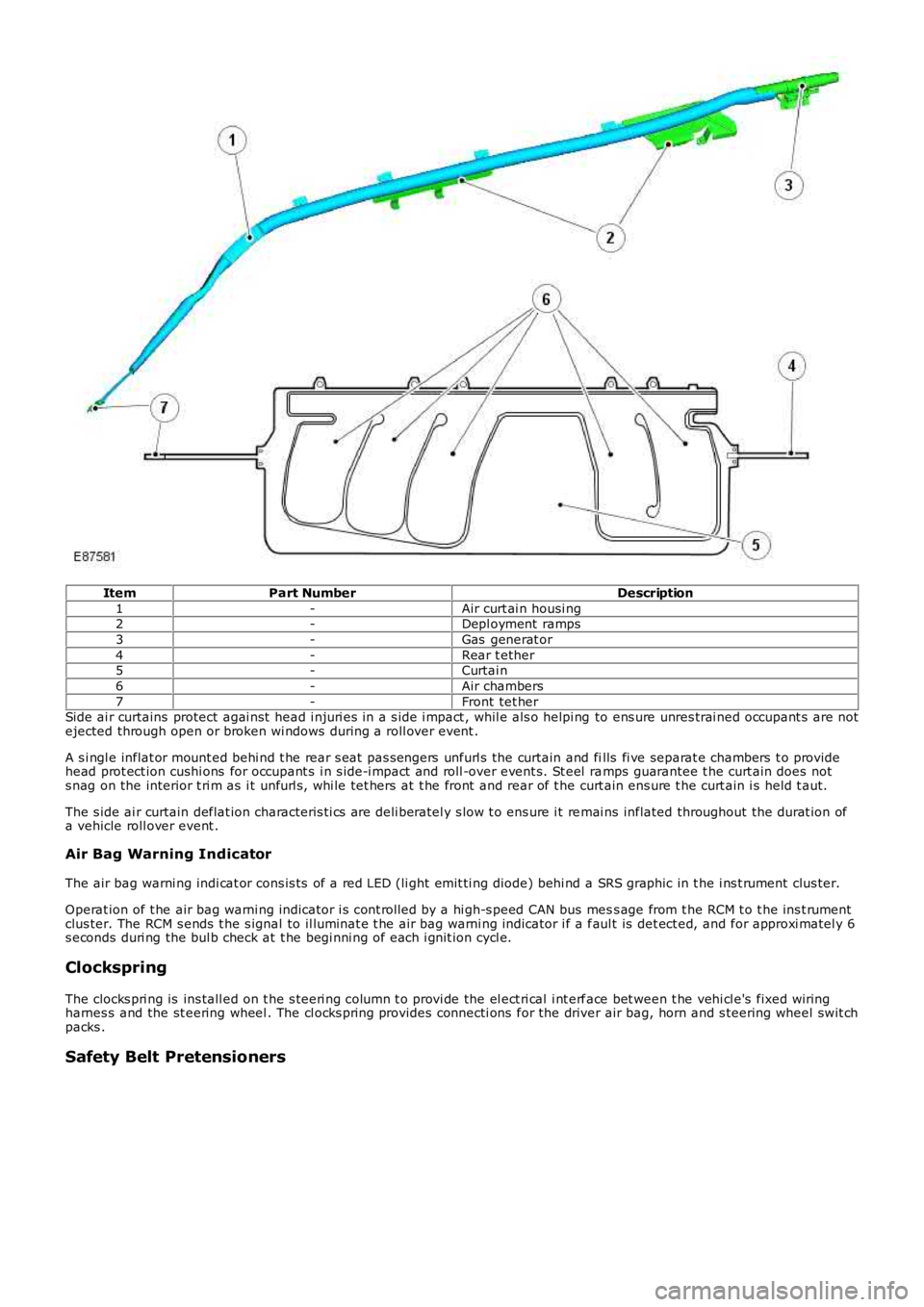
ItemPart NumberDescription
1-Air curt ai n housi ng2-Depl oyment ramps
3-Gas generat or
4-Rear t ether5-Curtai n
6-Air chambers
7-Front tet herSide ai r curtains protect agai nst head i njuri es in a s ide i mpact , whil e als o helpi ng to ens ure unres trai ned occupant s are notejected through open or broken wi ndows during a roll over event .
A s i ngl e inflat or mount ed behi nd t he rear s eat pas s engers unfurl s the curtain and fills fi ve separat e chambers t o providehead prot ect ion cushi ons for occupant s i n s ide-i mpact and roll -over event s. St eel ramps guarantee t he curt ain does nots nag on the interior t ri m as i t unfurl s , whi le tet hers at t he front and rear of t he curt ain ens ure t he curt ain i s held t aut.
The s ide ai r curtain deflat ion characteris ti cs are deli beratel y s low t o ens ure i t remai ns inflated throughout the durat ion ofa vehicle roll over event .
Air Bag Warning Indicator
The air bag warni ng indi cat or cons is ts of a red LED (li ght emit ti ng diode) behi nd a SRS graphic in t he i ns t rument clus ter.
Operat ion of t he air bag warni ng indicator i s cont rol led by a hi gh-s peed CAN bus mess age from t he RCM t o t he ins t rumentclus ter. The RCM s ends t he s ignal to il luminat e t he air bag warni ng indicator i f a faul t is det ect ed, and for approxi matel y 6s econds duri ng the bul b check at t he begi nni ng of each i gnit ion cycl e.
Clockspring
The clocks pri ng is ins tall ed on t he s teeri ng column t o provi de the el ect ri cal i nt erface bet ween t he vehi cl e's fixed wiringharnes s and the st eering wheel . The cl ocks pring provides connecti ons for the driver air bag, horn and s teering wheel swit chpacks .
Safety Belt Pretensioners
Page 2498 of 3229
Publi s hed: 11-May-2011
Supplemental Restraint System - Clockspring
Removal and Inst all ati on
Removal
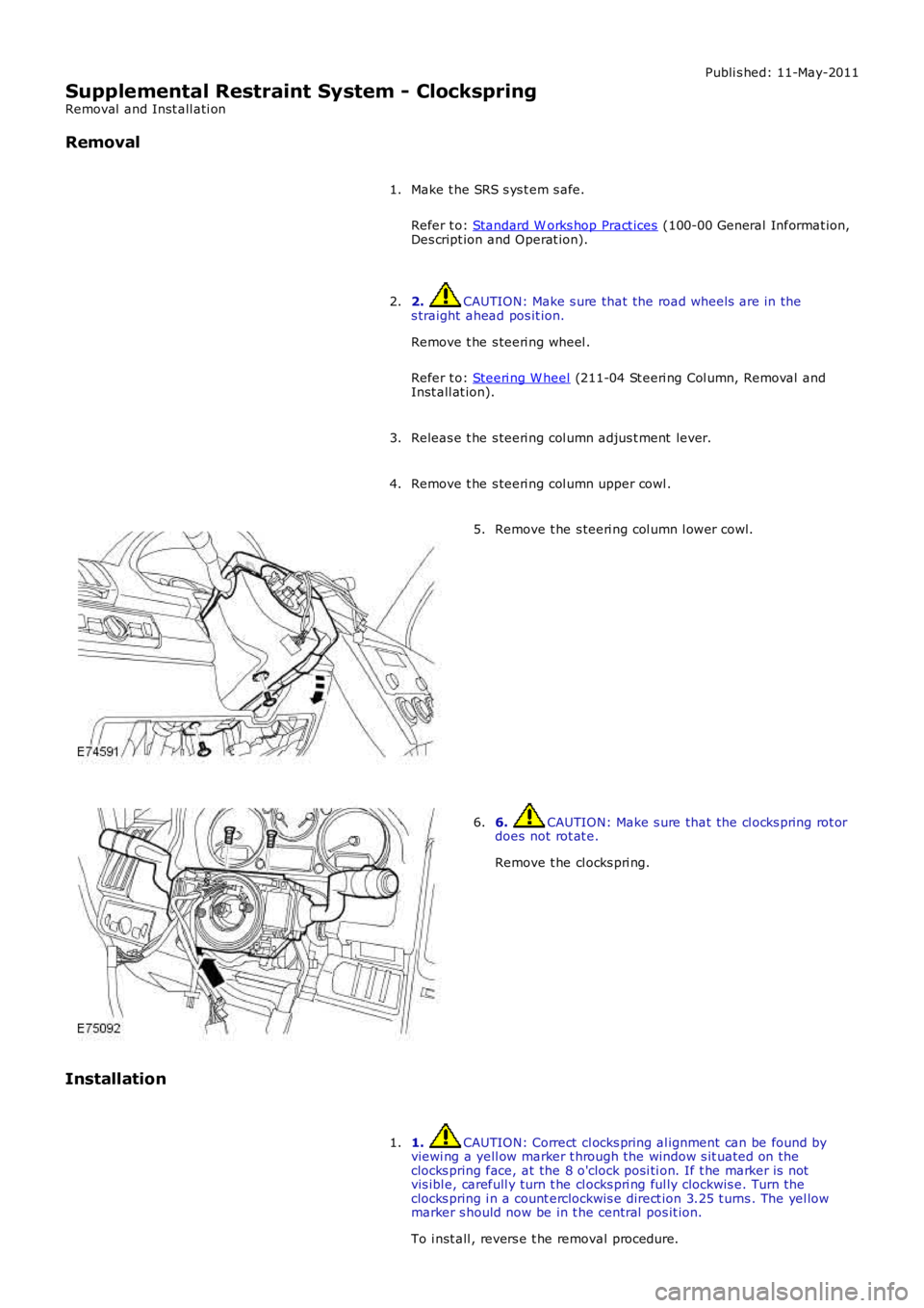
Make t he SRS s ys t em s afe.
Refer t o: Standard W orks hop Pract ices (100-00 General Informat ion,Des cript ion and Operat ion).
1.
2. CAUTION: Make s ure that the road wheels are in thes traight ahead pos it ion.
Remove t he s teeri ng wheel .
Refer t o: Steeri ng W heel (211-04 St eeri ng Col umn, Removal andInst all at ion).
2.
Releas e t he s teeri ng col umn adjus t ment lever.3.
Remove t he s teeri ng col umn upper cowl .4.
Remove t he s teeri ng col umn l ower cowl.5.
6. CAUTION: Make s ure that the cl ocks pring rot ordoes not rot at e.
Remove t he cl ocks pri ng.
6.
Installation
1. CAUTION: Correct cl ocks pring al ignment can be found byviewi ng a yell ow marker t hrough the window s it uated on theclocks pring face, at the 8 o'clock posi ti on. If t he marker is notvis ibl e, carefull y turn t he cl ocks pri ng ful ly clockwis e. Turn t heclocks pring i n a count erclockwis e direct ion 3.25 t urns . The yel lowmarker s hould now be in t he central pos it ion.
To i nst all , revers e t he removal procedure.
1.
Page 2724 of 3229

Contents
4
L
Climate control
AIR VENTS ................................................... 101
MANUAL CLIMATE CONTROL ...................... 102
AUTOMATIC CLIMATE CONTROL ................. 103
HEATED WINDOWS AND MIRRORS ............ 104
AUXILIARY HEATER ..................................... 104
ELECTRIC SUNROOF .................................... 105
Convenience features
SUN VISORS ................................................ 107
CLOCK .......................................................... 107
CIGAR LIGHTER ........................................... 109
ASHTRAY ..................................................... 109
AUXILIARY POWER SOCKETS ..................... 110
CUP HOLDERS ............................................. 111
STORAGE COMPARTMENTS ........................ 112
Starting the engine
GENERAL INFORMATION ............................. 113
STARTING A PETROL ENGINE ..................... 114
STARTING A DIESEL ENGINE ....................... 115
DIESEL PARTICULATE FILTER (DPF) ........... 116
Transmission
MANUAL TRANSMISSION ............................ 118
AUTOMATIC TRANSMISSION ...................... 118
TECHNICAL SPECIFICATIONS ...................... 122
Brakes
PRINCIPLE OF OPERATION .......................... 123
HINTS ON DRIVING WITH ABS .................... 123
PARKING BRAKE .......................................... 124
Parking aid
PRINCIPLE OF OPERATION .......................... 126
USING THE PARKING AID ............................ 127
Driving hints
GENERAL DRIVING POINTS ......................... 128
REDUCED ENGINE PERFORMANCE ............. 128
RUNNING-IN ................................................ 128
ECONOMICAL DRIVING ................................ 129
Cruise control
PRINCIPLE OF OPERATION .......................... 130
USING CRUISE CONTROL ............................ 130
Terrain response
PRINCIPLE OF OPERATION .......................... 132
USING TERRAIN RESPONSE ........................ 132
Hill descent control (HDC)
PRINCIPLE OF OPERATION .......................... 136
USING HDC ................................................... 137
Traction control
USING TRACTION CONTROL ........................ 139
Stability control
PRINCIPLE OF OPERATION .......................... 140
USING STABILITY CONTROL ........................ 141
Fuel and refuelling
SAFETY PRECAUTIONS................................. 142
FUEL QUALITY .............................................. 142
RUNNING OUT OF FUEL................................ 144
FUEL CUT-OFF............................................... 144
FUEL FILLER FLAP ........................................ 144
REFUELLING ................................................. 145
TECHNICAL SPECIFICATIONS ....................... 146
Load carrying
GENERAL INFORMATION.............................. 147
LUGGAGE ANCHOR POINTS ......................... 148
LUGGAGE COVERS ....................................... 149
Towing
TOWING A TRAILER...................................... 150
LEVELLING.................................................... 151
ESSENTIAL TOWING CHECKS ...................... 151
RECOMMENDED TOWING WEIGHTS ............ 152
TOW BAR ...................................................... 153
Vehicle care
CLEANING THE ALLOY WHEELS................... 154
CLEANING THE EXTERIOR ............................ 154
CLEANING THE INTERIOR ............................ 155
REPAIRING MINOR PAINT DAMAGE ............ 156
Maintenance
GENERAL INFORMATION.............................. 157
OPENING AND CLOSING THE BONNET......... 160
ENGINE COMPARTMENT OVERVIEW ........... 161
ENGINE OIL CHECK....................................... 162
Page 2751 of 3229
31
Quick start
R
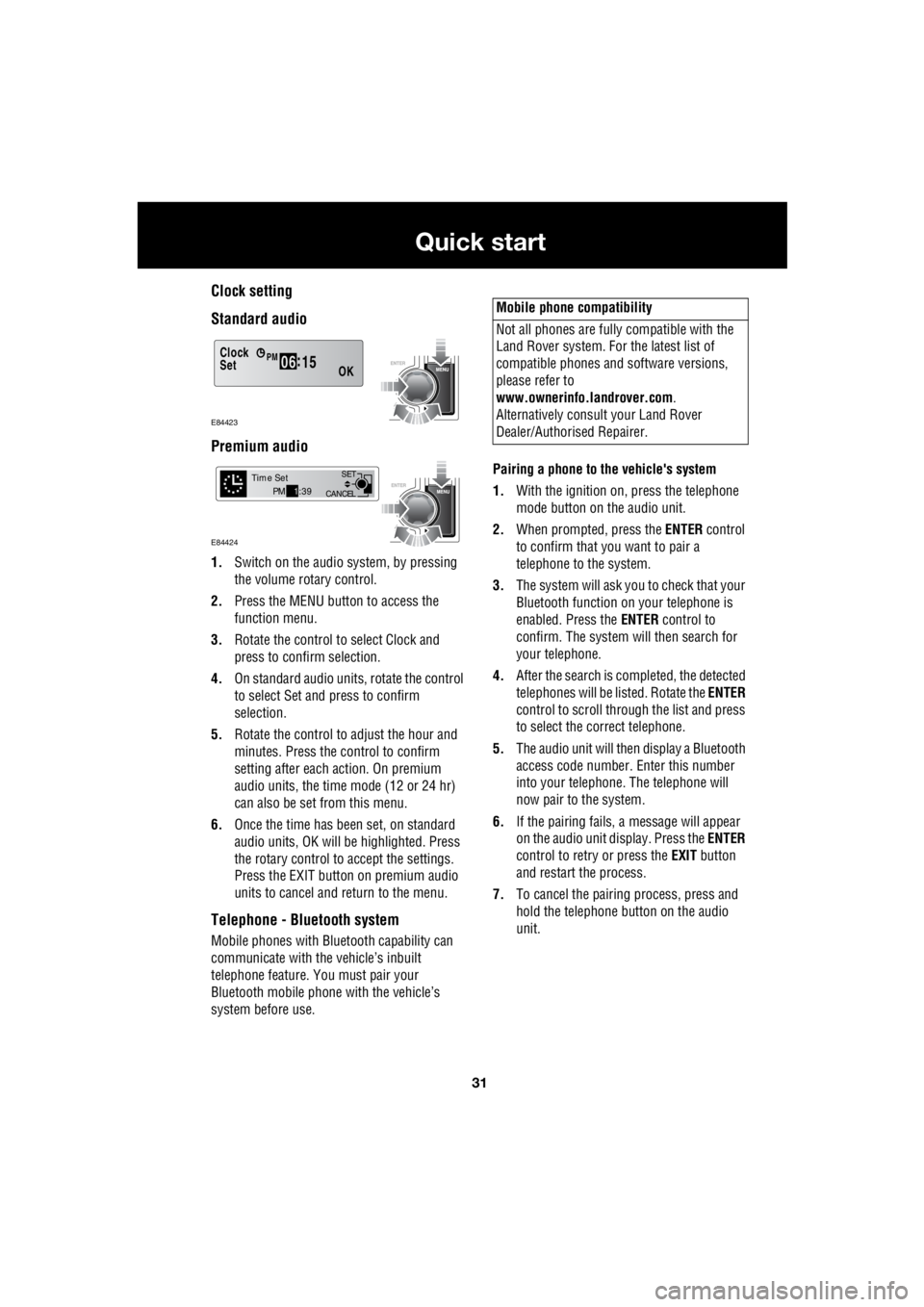
Clock setting
Standard audio
Premium audio
1. Switch on the audio system, by pressing
the volume rotary control.
2. Press the MENU button to access the
function menu.
3. Rotate the control to select Clock and
press to confirm selection.
4. On standard audio units, rotate the control
to select Set and press to confirm
selection.
5. Rotate the control to adjust the hour and
minutes. Press the c ontrol to confirm
setting after each action. On premium
audio units, the time mode (12 or 24 hr)
can also be set from this menu.
6. Once the time has been set, on standard
audio units, OK will be highlighted. Press
the rotary control to accept the settings.
Press the EXIT button on premium audio
units to cancel and return to the menu.
Telephone - Bluetooth system
Mobile phones with Blue tooth capability can
communicate with the vehicle’s inbuilt
telephone feature. You must pair your
Bluetooth mobile phone with the vehicle’s
system before use. Pairing a phone to the vehicle's system
1. With the ignition on, press the telephone
mode button on the audio unit.
2. When prompted, press the ENTER control
to confirm that you want to pair a
telephone to the system.
3. The system will ask you to check that your
Bluetooth function on your telephone is
enabled. Press the ENTER control to
confirm. The system will then search for
your telephone.
4. After the search is completed, the detected
telephones will be listed. Rotate the ENTER
control to scroll through the list and press
to select the correct telephone.
5. The audio unit will then display a Bluetooth
access code number. Enter this number
into your telephone. The telephone will
now pair to the system.
6. If the pairing fails, a message will appear
on the audio unit display. Press the ENTER
control to retry or press the EXIT button
and restart the process.
7. To cancel the pairing process, press and
hold the telephone button on the audio
unit.
Clock
OK06 :
15SetPM
E84423
CANCEL SET
Time SetPM
1:39
E84424
Mobile phone compatibility
Not all phones are fully compatible with the
Land Rover system. For the latest list of
compatible phones and software versions,
please refer to
www.ownerinfo.landrover.com .
Alternatively consult your Land Rover
Dealer/Authorised Repairer.
Page 2801 of 3229
81
Lighting
R
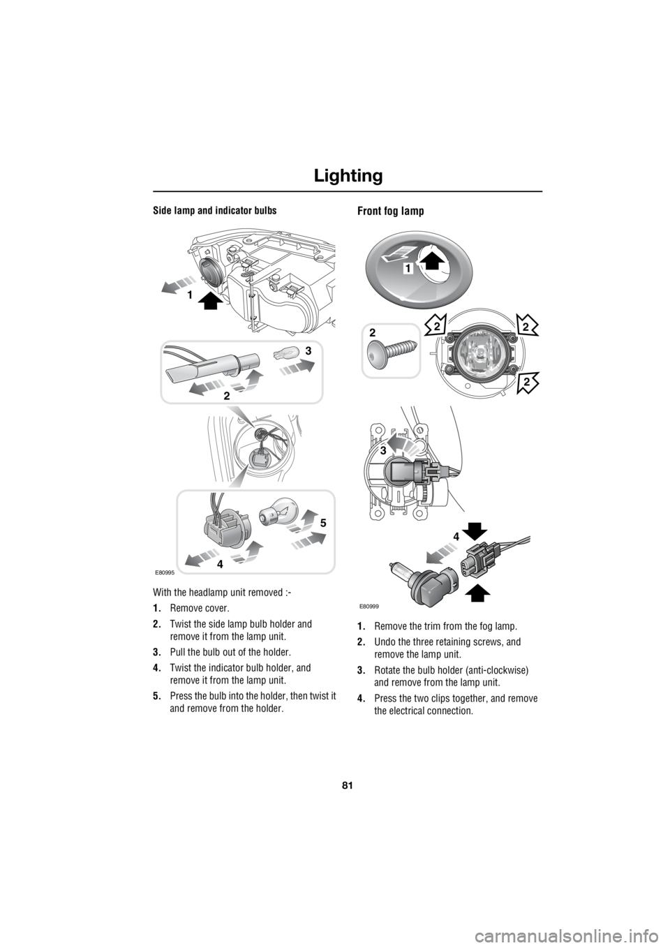
Side lamp and indicator bulbs
With the headlamp unit removed :-
1. Remove cover.
2. Twist the side lamp bulb holder and
remove it from the lamp unit.
3. Pull the bulb out of the holder.
4. Twist the indicato r bulb holder, and
remove it from the lamp unit.
5. Press the bulb into the holder, then twist it
and remove from the holder.Front fog lamp
1. Remove the trim from the fog lamp.
2. Undo the three retaining screws, and
remove the lamp unit.
3. Rotate the bulb holder (anti-clockwise)
and remove from the lamp unit.
4. Press the two clips together, and remove
the electrical connection.
E80995
2
3
4
5
1
1
22
2
E80999
2
3
4
Page 2802 of 3229
Lighting
82
L
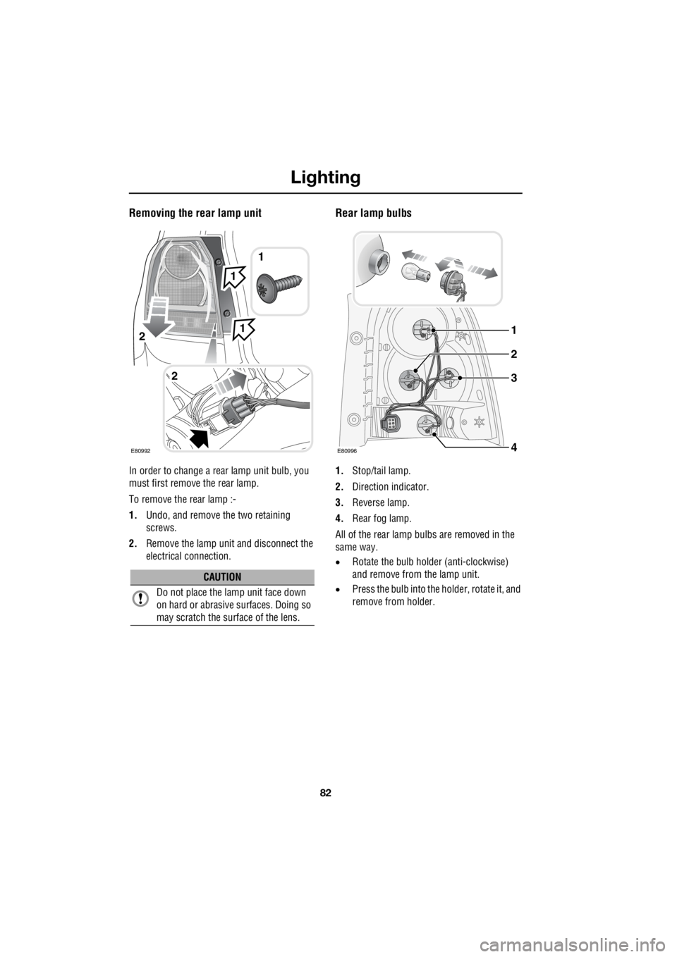
Removing the rear lamp unit
In order to change a re ar lamp unit bulb, you
must first remove the rear lamp.
To remove the rear lamp :-
1. Undo, and remove the two retaining
screws.
2. Remove the lamp unit and disconnect the
electrical connection.
Rear lamp bulbs
1. Stop/tail lamp.
2. Direction indicator.
3. Reverse lamp.
4. Rear fog lamp.
All of the rear lamp bulbs are removed in the
same way.
• Rotate the bulb holder (anti-clockwise)
and remove from the lamp unit.
• Press the bulb into the holder, rotate it, and
remove from holder.
CAUTION
Do not place the lamp unit face down
on hard or abrasive surfaces. Doing so
may scratch the surface of the lens.
2
1
E80992
2
1
1
E80996
1
3
2
4
Page 2827 of 3229
107
Convenience features
R
Convenience featuresSUN VISORS
CLOCK
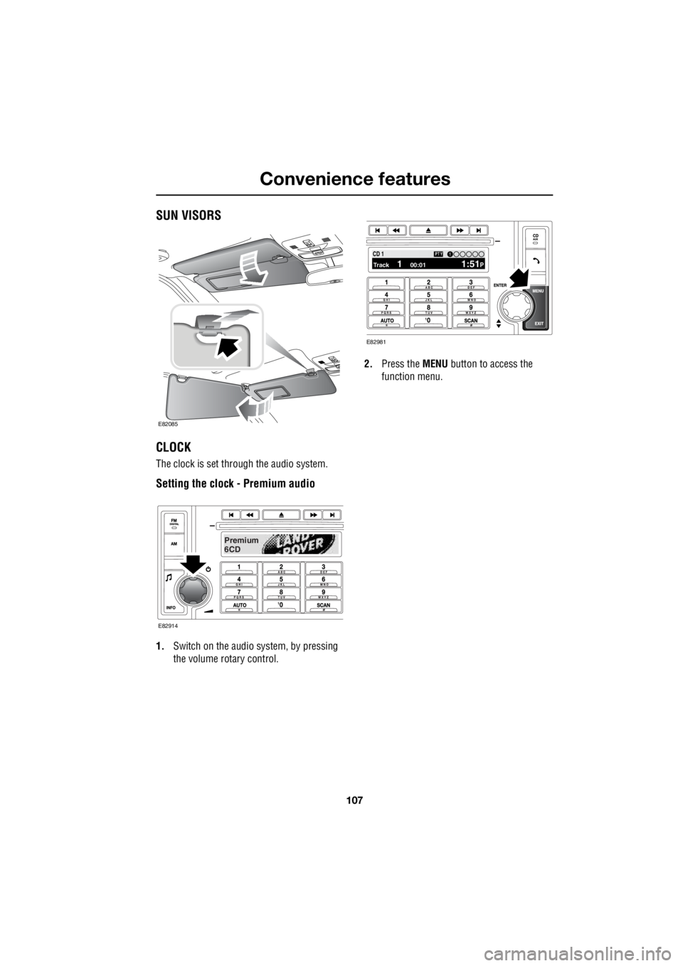
The clock is set through the audio system.
Setting the clock - Premium audio
1. Switch on the audio system, by pressing
the volume rotary control. 2.
Press the MENU button to access the
function menu.
E82085
Premium
6CD
E82914
100.71 12 3 4 6CD 1Track 1 00:01 1:51P
PTY1
E82981
Page 2828 of 3229
Convenience features
108
L
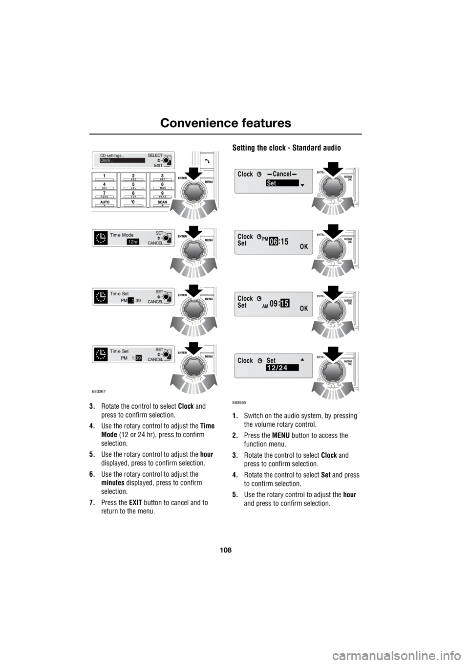
3. Rotate the control to select Clock and
press to confirm selection.
4. Use the rotary control to adjust the Time
Mode (12 or 24 hr), press to confirm
selection.
5. Use the rotary control to adjust the hour
displayed, press to confirm selection.
6. Use the rotary control to adjust the
minutes displayed, press to confirm
selection.
7. Press the EXIT button to cancel and to
return to the menu.
Setting the clock - Standard audio
1. Switch on the audio system, by pressing
the volume rotary control.
2. Press the MENU button to access the
function menu.
3. Rotate the control to select Clock and
press to confirm selection.
4. Rotate the control to select Set and press
to confirm selection.
5. Use the rotary control to adjust the hour
and press to c onfirm selection.
EXIT
SELECT
CD settings..
Clock..
CANCEL SET
Time Mode12hr
CANCELSET
Time SetPM
1:39
CANCEL SET
Time SetPM 1:
39
E83267
ClockCancel
Set
Clock
OK06 :
15SetPM
Clock
OK09 :
15SetAM
E83965
Clock12/24Set