Page 2293 of 3229

Refer t o: Glove Compart ment (501-12 Ins trument Panel andConsol e, Removal and Ins t al lat ion).
Inst all t he pas s enger s ide ins trument panel end trim panel .25.
Secure t he wiring harnes s s upport bracket .26.
Secure t he wiring harnes s t o t he cent er of the i nst rument panelupper s ecti on.27.
Inst all t he cl imat e control as s embly.28.
Inst all t he audi o unit .29.
Inst all t he cent er speaker.30.
Inst all t he video dis play.
Refer t o: Video Dis play (415-01 Informati on and Entert ainmentSyst em, Removal and Ins tall ati on).
31.
Inst all t he fl oor consol e.
Refer t o: Fl oor Cons ole (501-12 Inst rument Panel and Cons ole,Removal and Ins tall ati on).
32.
Inst all t he fl oor consol e extens ions.33.
Inst all both ins trument panel s peakers .34.
Inst all both upper t rim panels .35.
Connect t he in-vehi cl e t emperature s ens or electrical connect or.36.
Connect t he keyl es s s t art module elect rical connect or.37.
Secure t he ins trument cl ust er wiring harnes s cli p.38.
Inst all t he ins trument cl ust er.
Refer t o: Ins trument Clus ter (413-01 Ins t rument Clus t er, Removaland Inst all at ion).
39.
Inst all t he cl ocks pri ng.
Refer t o: Clocks pri ng (501-20B Supplement al Res t raint Sys tem,Removal and Ins tall ati on).
40.
Inst all both cowl s ide t rim panels .
Refer t o: Cowl Si de Tri m Panel (501-05 Interior Tri m andOrnament ati on, Removal and Ins tal lat ion).
41.
Secure both scuff pl ate t rim panels .42.
Inst all t he A-pi llar center t rim panels .43.
Page 2397 of 3229
further act ionrequired.NoReplace theglass panel(The drip lip isnot aservi ceablepart ).
Roof opening panel blind rewind procedure - Vehicles built up to VIN 154971
1. Close t he roof opening panel blind (but do not lat ch t he handle t o the frame ) .1.
• NOTE: Rot at e the roof opening panel in t he direct ions illus trat ed.
2. Releas e the roof opening panel blind from the runners.
Rota te t he left -hand e dge count er clockwise and releas e the right -hand edge from t he fra me.
2.
3. Open the roof opening panel blind.3.
Page 2398 of 3229
4. Releas e the roof opening panel blind from the mount ing bracke t and remove the roof opening panel blind from the vehicl e.
1. Push the roof ope ning panel blind in t o the frame t o releas e t he left -hand spring axle .2. Rot at e the roof opening panel blind count er clockwis e.3. Remove t he roof ope ning panel blind.
4.
• NOTE: The roof ope ning panel must be rewound 7 rotat ions .
5. Rewind the roof opening panel.
1. Using a s uit able tool, hol d a nd rotat e t he spring axle.2. Push the spring axle in t o the roof ope ning panel blind and al ign the s pring axle locking holes .3. Using s uit able pin or paperclip (as illustrat ed), lock t he spring axle.
5.
• NOTE: Make sure t hat the s pring axle is correct ly located into t he roof opening panel frame.
• NOTE: Make sure t hat the s uit able pin or paperclip rema ins in place while ins talling t he roof opening pa nel blind.
6. Inst all the roof ope ning panel blind t o t he frame.
6.
Page 2399 of 3229
Remove t he suit able pin or pape rclip from the roof opening panel blind once the roof opening panel has bee n correct lyinst alled.
7. Inst all the roof ope ning panel blind s liders to t he runners.
1. Push the roof ope ning panel blind right -hand slider in t o the runner.2. Inst all t he left -hand s lider clockwise t o t he runner.
7.
8. Open the roof opening panel blind and check for corre ct operati on.8.
Roof opening panel blind rewind procedure - Vehicles built from VIN 154972
1. Close t he roof opening panel blind.1.
• NOTE: Rot at e the roof opening panel in t he direct ions illus trat ed.
2. Releas e the roof opening panel blind from the runners.
Rota te t he left -hand e dge count er clockwise and releas e the right -hand edge from t he fra me.
2.
Page 2401 of 3229
• NOTE: Make sure t hat the s pring axle is correct ly located into t he roof opening panel frame.
6. Inst all the roof ope ning panel blind t o t he frame.
6.
7. Inst all the roof ope ning panel blind s liders to t he runners.
1. Push the roof ope ning panel blind right -hand slider in t o the runner.2. Inst all t he left -hand s lider clockwise t o t he runner.
7.
8. Open the roof opening panel blind and check for corre ct operati on.8.
Page 2405 of 3229

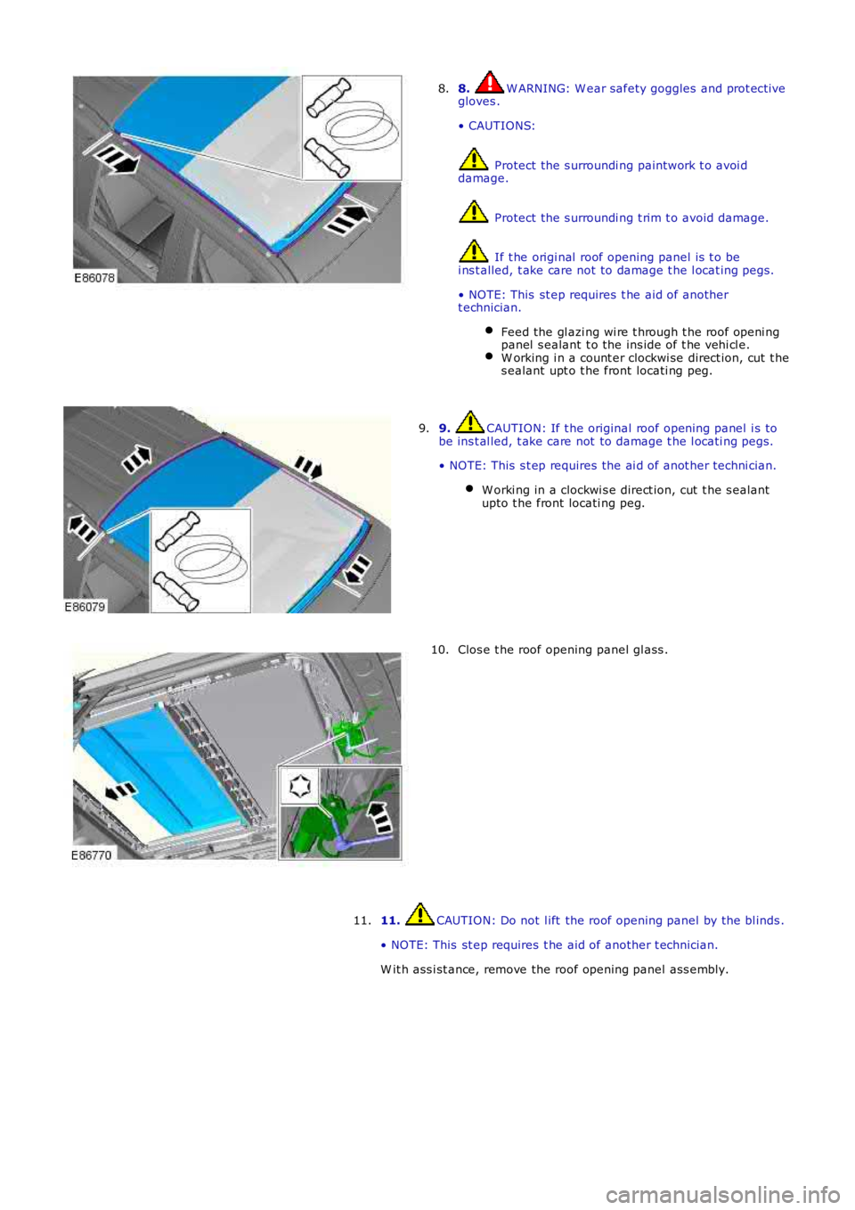
8. W ARNING: W ear safety goggles and prot ecti vegloves .
• CAUTIONS:
Protect the s urroundi ng paintwork t o avoi ddamage.
Protect the s urroundi ng t rim t o avoid damage.
If t he origi nal roof opening panel is t o bei ns t alled, t ake care not to damage t he l ocat ing pegs.
• NOTE: This st ep requires t he aid of anothert echnician.
Feed the gl azi ng wi re t hrough t he roof openi ngpanel s ealant t o the ins ide of t he vehi cl e.W orking i n a count er clockwi se direct ion, cut t hes ealant upt o t he front locati ng peg.
8.
9. CAUTION: If t he original roof openi ng panel i s tobe ins t al led, t ake care not to damage t he l ocati ng pegs.
• NOTE: This s t ep requires the ai d of anot her techni cian.
W orki ng in a clockwi s e direct ion, cut t he s ealantupto t he front locati ng peg.
9.
Clos e t he roof opening panel gl ass .10.
11. CAUTION: Do not l ift the roof opening panel by the bl inds .
• NOTE: This st ep requires t he aid of another t echnician.
W it h ass i st ance, remove the roof opening panel ass embly.
11.
Page 2474 of 3229
Publi s hed: 11-May-2011
Supplemental Restraint System - Air Bag and Safety Belt Pretensioner
Supplemental Restraint System (SRS)
Des cript ion and Operat ion
COMPONENT LOCATION SHEET 1 OF 2
ItemPart NumberDescription
1-Pas s enger air bag
2-Adapt ive s teering column3-Clocks pri ng
4-Dri ver air bag
5-Dri ver l ower ai r bag6-Res t raint s Control Modul e (RCM)
7-Pas s enger air bag deacti vat ion s wi tch
COMPONENT LOCATION SHEET 2 OF 2
Page 2478 of 3229

12-Seat pos i ti on sens or
13-Pas senger ai r bag deact ivati on s wit ch
14-Driver safety belt buckle s wi tch15-Pas senger safety belt buckle s wi tch
16-Impact s ens or - l eft -hand front
17-Impact s ens or - right -hand front18-Side impact sens or - left -hand B-pil lar
19-Side impact sens or - ri ght -hand B-pill ar
20-Side impact sens or - left -hand C-pil lar21-Side impact sens or - ri ght -hand C-pill ar
22-Driver lower air bag
23-Adapti ve st eeri ng col umn24-Side ai r bag – l eft-hand
25-Side ai r bag – right-hand
26-Clockspring27-Pas senger ai r bag
28-Driver ai r bag
29-Curt ain ai r bag – l eft-hand30-Curt ain ai r bag – right-hand
PRINCIPLES OF OPERATION
Crash Sensing
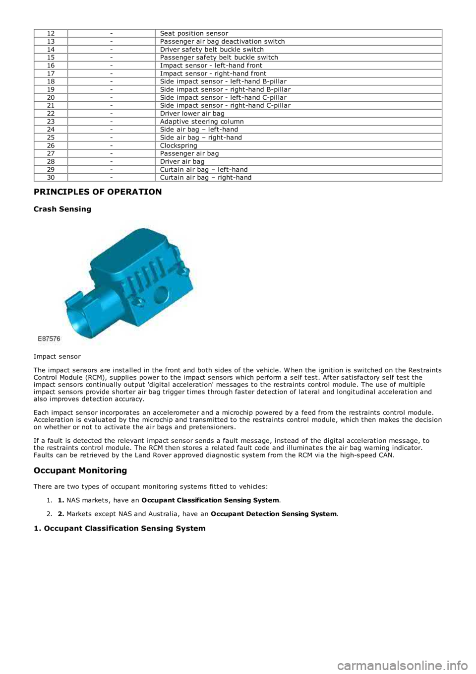
Impact s ensor
The impact s ens ors are i nst all ed in the front and both si des of the vehicle. W hen the i gni ti on is swi tched on t he Res trai ntsControl Module (RCM), s uppli es power to t he i mpact s ensors which perform a s elf t es t. After s ati sfact ory sel f tes t theimpact s ens ors cont inually out put 'digi tal accelerat ion' mes s ages t o t he res t raint s cont rol module. The us e of mult ipl eimpact s ens ors provide s hort er ai r bag trigger ti mes t hrough fas t er det ect ion of l ateral and l ongit udinal accelerat ion andals o i mproves detecti on accuracy.
Each impact sens or incorporat es an acceleromet er and a mi crochi p powered by a feed from the res traints cont rol module.Accelerati on is evaluat ed by the microchip and t rans mi tt ed t o the res traints cont rol module, which t hen makes the decis ionon whether or not to act ivate the ai r bags and pretens ioners .
If a fault is detect ed the relevant impact sens or sends a fault mes s age, i ns t ead of the di gi tal accel erati on mes s age, t ot he res traint s cont rol module. The RCM t hen s tores a rel ated fault code and il luminat es the ai r bag warning indicator.Faul ts can be ret rieved by t he Land Rover approved diagnos t ic s ys tem from t he RCM via t he high-s peed CAN.
Occupant Monitoring
There are t wo t ypes of occupant monit oring s ys tems fi tt ed to vehi cl es:
1. NAS market s , have an O ccupant Classification Sensing System.1.
2. Markets except NAS and Aust ral ia, have an Occupant Detection Sensing System.2.
1. Occupant Classification Sensing System