2006 LAND ROVER FRELANDER 2 steering wheel
[x] Cancel search: steering wheelPage 24 of 3229
shows signs of fraying.Alw ays disconnect the vehicle battery before carrying out any electric welding on a vehicle installed with anSRS system.
CAUTION: Do not expos e ai rbag modules or s eat belt pre-tens ioners t o t emperat ures exceeding 85° C (185° F).
It should be not ed t hat thes e precaut ions are not res trict ed to operat ions performed when s ervicing t he SRS s yst em. Thes ame care s hould be exerci sed when working on ancil lary sys t ems and components located i n the vi ci nit y of SRScomponents ; t hese include but are not l imi ted t o:
Steering wheel ai rbag, rot ary coupler.Pass enger front airbag.Side curt ain ai rbag modules - front and rear.Seat bel t pre-t ensi oners .SRS harnes ses , li nk leads and connectors.Side (t horax) ai r bags .
Making t he s ys t em s afe
Before working on or in t he vicini ty of SRS component s , make s ure t he s ys t em i s rendered safe by performi ng the foll owingoperati ons :
Remove the remot e cont rol .Dis connect batt ery, eart h lead first .W ai t 2 mi nut es for t he SRS power ci rcuit t o di scharge before commenci ng work.
• NOTE: The SRS us es energy res erve capaci tors to keep t he s yst em act ive i n t he event of electrical supply fail ure undercras h condi ti ons . It is necess ary to al low the capaci tors s uffi ci ent ti me t o dis charge (2 mi nut es ) in order t o avoid t he ris kof accidental deployment.
Ins t allat ion
In order to make s ure s ys tem int egrit y, it is ess enti al t hat the SRS sys tem is regularl y checked and mai nt ained s o t hat itis ready for effecti ve operat ion in t he event of a col lis i on. Carefully ins pect SRS component s before ins tal lati on. Do notins t al l a part t hat shows s i gns of being dropped or i mproperl y handl ed, s uch as dents , cracks or deformat ion.
W ARNING: The integrit y of the SRS sys tems is crit ical for safety reasons . Make s ure t he fol lowing precaut ions arealways adhered t o:
Do not install accessories or other objects to trim panels w hich cover airbags.Never install used SRS components from another vehicle or attempt to repair an SRS component.When repairing an SRS system, only use genuine new parts.Never apply electrical power to an SRS component unless instructed to do so as part of an approved testprocedure.Special fixings are necessary for installing an airbag module – do not use other fixings.Alw ays use new fixings w hen replacing an SRS component and make sure that all fixings are tightened to thecorrect torque.
• CAUTIO NS:
Take care not t o t rap airbag modules when i nst all ing i nt eri or trim components .
Make s ure SRS components are not cont aminat ed by oil or greas e.
• NOTE: Followi ng s eat bel t pre-t ensi oner deployment, t he s eat bel ts can s t ill be used as convent ional seat belt s but wil lneed to be replaced as s oon as poss i bl e t o make s ure full SRS protecti on. Do not us e t he s eat bel ts if t he ret racti onmechani sm i s not working correct ly.
• NOTE: If the SRS component s are to be repl aced, the part number/bar code of the new uni t mus t be recorded.
SRS component t es t ing precauti ons
The SRS component s are t riggered us ing relati vel y l ow operati ng current s, al ways adhere to the foll owing :
W ARNING: Never us e a mul ti meter or ot her general purpose equi pment on SRS components. Us e only Land Roverapproved diagnos t ic equipment t o diagnos e sys tem faul ts .
Page 28 of 3229
Make s ure deployment tool is connect ed correct ly, in compl iance wit h t he ins truct ions det ai led i n t he SRS s ect ion oft hi s manual. In part icular, make sure depl oyment t ool is NOT connect ed t o batt ery s upply before connecti ng t oairbag modul e connector.W hen deploying s eat belt pre-tens ioners , make s ure pre-t ensi oner unit i s s ecured correctl y t o t he s eat .W hen removing deployed airbag modul es and pre-tens ioner uni ts , wear protecti ve clothi ng. Us e gl oves and s ealdepl oyed uni ts in a pl ast ic bag.Followi ng depl oyment of any component of t he SRS s ys t em wi thi n the vehicl e, al l SRS components mus t berepl aced. DO NOT reus e or s al vage any parts of t he SRS s yst em.Do not lean over an airbag module when connect ing deployment equi pment .
If a vehi cl e i s to be s crapped, undepl oyed ai rbag modules and pre-t ens ioner unit s mus t be manually depl oyed. In thi s cas eairbags can be deployed i n the vehicl e. Before deployment, make s ure the ai rbag modul e is secure wit hi n i ts correctmounti ng posi ti on. Deployment of the driver's airbag in the vehicle may damage the st eering wheel ; if t he vehi cl e i s notbeing s crapped, deploy t he module out s ide of t he vehi cl e.
SRS Component Replacement Policy
• CAUTIO NS:
T he restraints control module (RCM) must be replaced after every time any SRS component has beendeployed.
The SRS s ide impact sens or mus t be replaced if t here are any s igns of phys i cal damage or if t he RCM i s regi st eri ng afaul t.
The fol lowing informati on detail s t he policy for replacement of SRS component s as a res ult of a vehicle accident.
Impacts w hich do not deploy the airbags or pre-tensioners
Check for s truct ural damage in t he area of the i mpact paying parti cular at tent ion t o bumper armat ures , longi tudi nal s andbracket ry.
Impacts w hich deploy the airbags or pre-tensioners
The repl acement and ins pect ion poli cy is dependent on t he t ype and severi ty of t he cras h condi ti on. The foll owingguideli nes are t he mi ni mum that s houl d be exercis ed as a res ul t of the deployment of s pecific SRS component s .
Check for structural damage in the area of impact paying particular attention to bumper armatures, longitudinalsand bracketry.
Front Airbag Deployment - Driver and Passenger
CAUTION: If the front airbags are deployed, the followi ng components mus t be replaced:
Dri ver ai rbag moduleSteering wheelPass enger ai rbag moduleIns t rument panelFly l eads (where appl icabl e) connect ing front ai rbag modules t o SRS harnes sAll s eat bel t buckle pre-t ensi onerAll occupied seat s at the ti me of t he crash s hould have their s eat bel ts replacedAny s eat bel t wit h a deployed ret ract or pretens ioner s hould be replaced.Rotary couplerAny front impact s ens ors that have been phys ically damaged or i f a faul t is being regis teredRCM
Additionally, the following items must be inspected for damage and replaced as necessary:
Front pass enger's seat belt retract or and webbi ng, t ongue l atching funct ion, 'D' loop and body anchorage poi ntRear seat belt buckl es, webbing, buckle covers , body anchorage point s and t ongue l atching funct ionFront s eat frames and head res trai ntsSteering column - if adjus tment i s los t or if t here are s igns of col laps eSeat bel t hei ght adjust ersRear seat belt s
Side Ai r Bags
CAUTION: If the s i de (t horax) air bags are deployed, the foll owi ng component s mus t be replaced on t he s ide of t hevehi cl e on whi ch the deployment occurred:
Side (t horax) ai rbagAny s ide i mpact s ens ors t hat have been phys i cal ly damaged or if a fault i s being regi st eredRCM
Additionally, the following items must be inspected for damage and replaced as necessary:
Front s eat bel ts , ret ractors and webbing, tongue lat chi ng functi on, 'D' l oop and body anchorage point sRear seat belt buckl es, webbing, buckle covers , t ongue l atching funct ion, and body anchorage point sFront s eat frame and head res traint sDoor trim cas i ngSeat bel t hei ght adjust ers
Page 54 of 3229
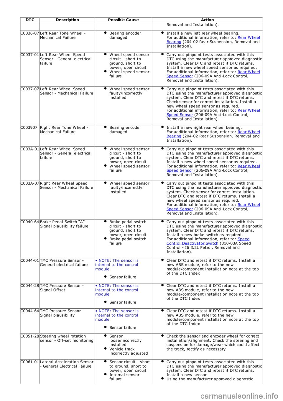
DT CDescriptionPossible CauseAction
Removal and Ins t allat ion).
C0036-07Left Rear Tone W heel -Mechanical Fai lureBearing encoderdamagedIns tal l a new l eft rear wheel bearing.For addit ional informati on, refer t o: Rear W heelBearing (204-02 Rear Sus pensi on, Removal andIns tal lati on).
C0037-01Left Rear W heel SpeedSens or - General electricalfai lure
W heel speed s ensorci rcuit - s hort t oground, s hort t opower, open ci rcuitW heel speed s ensorfail ure
Carry out pi npoi nt t es ts as s oci ated wi th thi sDTC usi ng t he manufacturer approved diagnost icsys tem. Cl ear DTC and ret est i f DTC ret urns .Ins tal l a new wheel speed s ensor as requi red.For addit ional informati on, refer t o: Rear W heelSpeed Sens or (206-09A Anti -Lock Control ,Removal and Ins t allat ion).
C0037-07Left Rear W heel SpeedSens or - Mechani cal FailureW heel speed s ensorfault y/i ncorrect lyins tal led
Carry out pi npoi nt t es ts as s oci ated wi th thi sDTC usi ng t he manufacturer approved diagnost icsys tem. Cl ear DTC and ret est i f DTC ret urns .Check s ensor for correct ins tall ati on. Inst all anew wheel s peed s ens or as required.For addit ional informati on, refer t o: Rear W heelSpeed Sens or (206-09A Anti -Lock Control ,Removal and Ins t allat ion).
C003907Right Rear Tone W heel -Mechanical Fai lureBearing encoderdamagedIns tal l a new right rear wheel beari ng.For addit ional informati on, refer t o: Rear W heelBearing (204-02 Rear Sus pensi on, Removal andIns tal lati on).
C003A-01Left Rear W heel SpeedSens or - General electricalfai lure
W heel speed s ensorci rcuit - s hort t oground, s hort t opower, open ci rcuitW heel speed s ensorfail ure
Carry out pi npoi nt t es ts as s oci ated wi th thi sDTC usi ng t he manufacturer approved diagnost icsys tem. Cl ear DTC and ret est i f DTC ret urns .Ins tal l a new wheel speed s ensor as requi red.For addit ional informati on, refer t o: Rear W heelSpeed Sens or (206-09A Anti -Lock Control ,Removal and Ins t allat ion).
C003A-07Right Rear W heel SpeedSens or - Mechani cal FailureW heel speed s ensorfault y/i ncorrect lyins tal led
Carry out pi npoi nt t es ts as s oci ated wi th thi sDTC usi ng t he manufacturer approved diagnost icsys tem. Check s ens or for correct i nst all ati on.Clear DTC and ret est i f DTC ret urns . Ins t all anew wheel s peed s ens or as required.For addit ional informati on, refer t o: Rear W heelSpeed Sens or (206-09A Anti -Lock Control ,Removal and Ins t allat ion).
C0040-64Brake Pedal Swi tch “A” -Signal pl ausi bili ty fail ureBrake pedal s wi tchci rcuit - s hort t oground, s hort t opower, open ci rcuitBrake pedal s wi tchfail ure
Carry out pi npoi nt t es ts as s oci ated wi th thi sDTC usi ng t he manufacturer approved diagnost icsys tem. Cl ear DTC and ret est i f DTC ret urns .Ins tal l a new brake s wi tch as requi red.For addit ional informati on, refer t o: SpeedCont rol Deact ivat or Swi tch (310-03A SpeedCont rol - I6 3.2L Pet rol, Removal andIns tal lati on).
C0044-01TMC Pres s ure Sens or -General elect rical fail ure• NOTE: The s ens or isint ernal t o t he cont rolmodul e
Sens or fai lure
Clear DTC and ret est i f DTC ret urns . Ins t all anew ABS module, refer to the newmodul e/component i ns t allat ion not e at t he topof t he DTC Index
C0044-28TMC Pres s ure Sens or -Signal Offset• NOTE: The s ens or isint ernal t o t he cont rolmodul e
Sens or fai lure
Clear DTC and ret est i f DTC ret urns . Ins t all anew ABS module, refer to the newmodul e/component i ns t allat ion not e at t he topof t he DTC Index
C0044-64TMC Pres s ure Sens or -Signal pl ausi bili ty• NOTE: The s ens or isint ernal t o t he cont rolmodul e
Sens or fai lure
Clear DTC and ret est i f DTC ret urns . Ins t all anew ABS module, refer to the newmodul e/component i ns t allat ion not e at t he topof t he DTC Index
C0051-28Steering wheel rot at ions ens or - Off-set moni toringSens orloos e/incorrect lyins tal ledVehi cl e t rackincorrect ly adjus t ed
Check t he s ens or and encoder wheel for correctins tall ati on/ali gnment . Check t he s teering andsus pens i on for damage/wear which could affectthe t rack, recti fy as necess ary
C0061-01Lateral Accel erati on Sensor- General Electrical Fail ureSens or ci rcuit - s hortto ground, s hort t opower, open ci rcuitInt ernal sens orfail ure
Carry out pi npoi nt t es ts as s oci ated wi th thi sDTC usi ng t he manufacturer approved diagnost icsys tem. Cl ear DTC and ret est i f DTC ret urns .Ins tal l a new s ensorUsi ng t he manufact urer approved diagnost ic
Page 73 of 3229
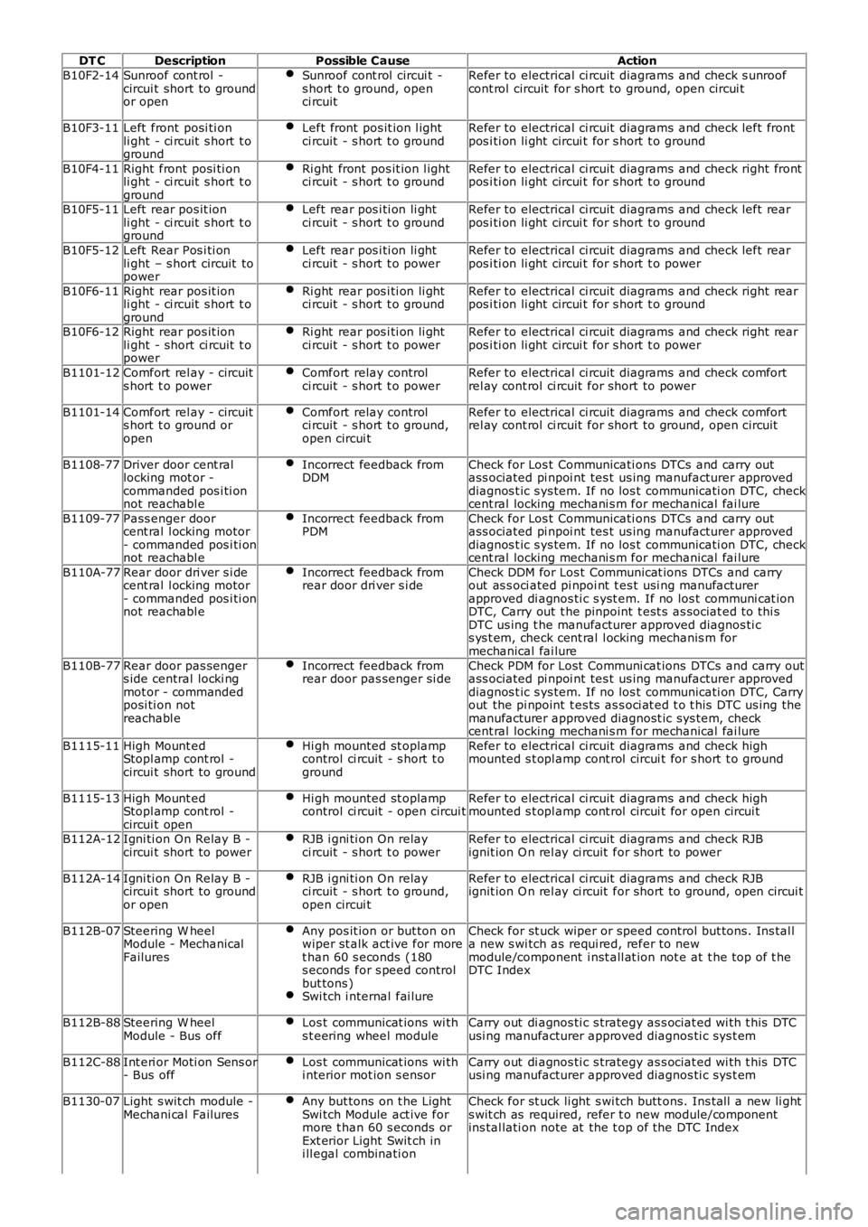
DT CDescriptionPossible CauseAction
B10F2-14Sunroof cont rol -circui t short to groundor open
Sunroof cont rol circui t -s hort t o ground, openci rcuit
Refer to electrical ci rcuit diagrams and check s unroofcont rol circuit for s hort to ground, open circui t
B10F3-11Left front posi ti onli ght - ci rcuit s hort t oground
Left front pos it ion l ightci rcuit - s hort t o groundRefer to electrical ci rcuit diagrams and check left frontpos i ti on li ght circui t for s hort t o ground
B10F4-11Right front posi ti onli ght - ci rcuit s hort t oground
Ri ght front pos it ion l ightci rcuit - s hort t o groundRefer to electrical ci rcuit diagrams and check right frontpos i ti on li ght circui t for s hort t o ground
B10F5-11Left rear pos it ionli ght - ci rcuit s hort t oground
Left rear pos i ti on li ghtci rcuit - s hort t o groundRefer to electrical ci rcuit diagrams and check left rearpos i ti on li ght circui t for s hort t o ground
B10F5-12Left Rear Pos i ti onli ght – s hort circuit topower
Left rear pos i ti on li ghtci rcuit - s hort t o powerRefer to electrical ci rcuit diagrams and check left rearpos i ti on li ght circui t for s hort t o power
B10F6-11Right rear pos it ionli ght - ci rcuit s hort t oground
Ri ght rear pos i ti on li ghtci rcuit - s hort t o groundRefer to electrical ci rcuit diagrams and check right rearpos i ti on li ght circui t for s hort t o ground
B10F6-12Right rear pos it ionli ght - short ci rcuit t opower
Ri ght rear pos i ti on li ghtci rcuit - s hort t o powerRefer to electrical ci rcuit diagrams and check right rearpos i ti on li ght circui t for s hort t o power
B1101-12Comfort rel ay - circuits hort t o powerComfort relay controlci rcuit - s hort t o powerRefer to electrical ci rcuit diagrams and check comfortrel ay cont rol ci rcuit for short to power
B1101-14Comfort rel ay - circuits hort t o ground oropen
Comfort relay controlci rcuit - s hort t o ground,open circui t
Refer to electrical ci rcuit diagrams and check comfortrel ay cont rol ci rcuit for short to ground, open circui t
B1108-77Driver door cent rallocking mot or -commanded pos i ti onnot reachabl e
Incorrect feedback fromDDMCheck for Los t Communicati ons DTCs and carry outass ociated pi npoi nt tes t us ing manufacturer approveddiagnos t ic s ys tem. If no los t communicati on DTC, checkcent ral locking mechani s m for mechanical fai lure
B1109-77Pass enger doorcent ral l ocking motor- commanded pos i ti onnot reachabl e
Incorrect feedback fromPDMCheck for Los t Communicati ons DTCs and carry outass ociated pi npoi nt tes t us ing manufacturer approveddiagnos t ic s ys tem. If no los t communicati on DTC, checkcent ral locking mechani s m for mechanical fai lure
B110A-77Rear door dri ver s i decent ral l ocking motor- commanded pos i ti onnot reachabl e
Incorrect feedback fromrear door dri ver s i deCheck DDM for Los t Communicat ions DTCs and carryout as s oci ated pi npoi nt t es t usi ng manufacturerapproved di agnos ti c s yst em. If no los t communi cat ionDTC, Carry out t he pinpoint t est s as sociat ed t o thi sDTC us ing t he manufacturer approved diagnos ti cs ys t em, check cent ral l ocking mechanis m formechanical fai lure
B110B-77Rear door pas sengers ide central locki ngmot or - commandedposi ti on notreachabl e
Incorrect feedback fromrear door pas senger si deCheck PDM for Lost Communi cat ions DTCs and carry outass ociated pi npoi nt tes t us ing manufacturer approveddiagnos t ic s ys tem. If no los t communicati on DTC, Carryout the pi npoint t es ts as s oci at ed t o t his DTC us ing themanufacturer approved diagnost ic sys tem, checkcent ral locking mechani s m for mechanical fai lure
B1115-11High Mount edStopl amp cont rol -circui t short to ground
Hi gh mounted st oplampcontrol ci rcuit - s hort t oground
Refer to electrical ci rcuit diagrams and check highmounted s t opl amp cont rol circui t for s hort t o ground
B1115-13High Mount edStopl amp cont rol -circui t open
Hi gh mounted st oplampcontrol ci rcuit - open circui tRefer to electrical ci rcuit diagrams and check highmounted s t opl amp cont rol circui t for open circui t
B112A-12Igni ti on On Relay B -circui t short to powerRJB i gni ti on On relayci rcuit - s hort t o powerRefer to electrical ci rcuit diagrams and check RJBignit ion O n rel ay ci rcuit for short to power
B112A-14Igni ti on On Relay B -circui t short to groundor open
RJB i gni ti on On relayci rcuit - s hort t o ground,open circui t
Refer to electrical ci rcuit diagrams and check RJBignit ion O n rel ay ci rcuit for short to ground, open circui t
B112B-07Steering W heelModule - MechanicalFailures
Any pos it ion or but ton onwiper st alk act ive for moret han 60 s econds (180s econds for s peed controlbut tons )Swi tch i nternal fai lure
Check for st uck wiper or speed control but tons . Ins tal la new s wi tch as requi red, refer to newmodule/component i nst all at ion not e at t he top of t heDTC Index
B112B-88Steering W heelModule - Bus offLos t communicat ions wi ths t eering wheel moduleCarry out di agnos ti c s trategy as s ociat ed wi th t his DTCusi ng manufacturer approved diagnos ti c sys t em
B112C-88Int eri or Moti on Sens or- Bus offLos t communicat ions wi thi nterior mot ion s ensorCarry out di agnos ti c s trategy as s ociat ed wi th t his DTCusi ng manufacturer approved diagnos ti c sys t em
B1130-07Light s wit ch module -Mechani cal FailuresAny but tons on t he LightSwi tch Module act ive formore t han 60 s econds orExt erior Light Swit ch ini ll egal combinati on
Check for st uck li ght s wi tch butt ons. Ins tall a new li ghts wit ch as required, refer t o new module/componentins tal lati on note at the t op of the DTC Index
Page 77 of 3229
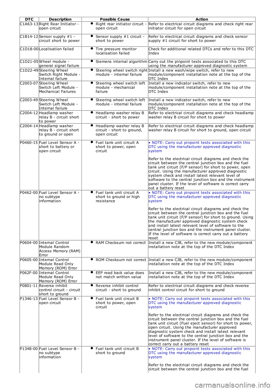
DT CDescriptionPossible CauseAction
C1A63-13Right Rear Ini ti at or -open circuitRi ght rear init iat or ci rcuit -open circui tRefer to electrical ci rcuit diagrams and check right rearinit iat or ci rcuit for open ci rcuit
C1B14-12Sensor s uppl y #1 -circui t short to powerSens or supply #1 circuit -s hort t o powerRefer to electrical ci rcuit diagrams and check s ens ors upply #1 circui t for s hort t o power
C1D18-00Local is ati on fail edTi re press ure monit orl ocal is ati on fai ledCheck for addi ti onal rel ated DTCs and refer t o thi s DTCIndex
C1D21-05W heel module -general si gnal failureSi emens int ernal al gorit hmCarry out the pi npoint t es ts as s oci at ed t o t his DTCusi ng t he manufact urer approved diagnost ic s ys tem
C1D22-49Steering W heelSwit ch Right Module -Int ernal fai lure
St eering wheel s wit ch ri ghtmodul e - int ernal fai lureIns t al l a new was h/wi pe s wit ch, refer t o newmodule/component i nst all at ion not e at t he top of t heDTC IndexC2003-07Steering W heelSwit ch Left Module -Mechani cal Failures
St eering wheel s wit ch leftmodul e - mechani calfail ure
Ins t al l a new i ndi cat or swit ch, refer to newmodule/component i nst all at ion not e at t he top of t heDTC Index
C2003-49Steering W heelSwit ch Left Module -Int ernal fai lure
St eering wheel s wit ch leftmodul e - int ernal fai lureIns t al l a new i ndi cat or swit ch, refer to newmodule/component i nst all at ion not e at t he top of t heDTC Index
C2004-12Headlamp was herrel ay B - circui t s hortt o power
Headlamp washer rel ay Bci rcuit - s hort t o powerRefer to electrical ci rcuit diagrams and check headl ampwasher rel ay B circui t for s hort t o power
C2004-14Headlamp was herrel ay B - circui t s hortt o ground or open
Headlamp washer rel ay Bci rcuit - s hort t o ground,open circui t
Refer to electrical ci rcuit diagrams and check headl ampwasher rel ay B circui t for s hort t o ground, open ci rcuit
P0460-15Fuel Level Sens or A -s hort t o batt ery oropen circuit
Fuel tank unit ci rcuit As hort t o power, openci rcuit
• NOTE: Carry out pi npoi nt tes ts ass ociated wit h t hi sDTC us ing t he manufacturer approved diagnos ti cs ys t em
Refer to the el ect ri cal circui t diagrams and check theci rcuit bet ween the central junct ion box and the fueltank unit ci rcuit (F/P s ensor) for s hort t o power, openci rcuit . Us ing t he manufacturer approved diagnos ti cs ys t em check and i nst all l at es t relevant level ofs oftware t o t he cent ral juncti on box and t he ins trumentpanel clus ter. If t he level of software is correct carryout a batt ery reset
P0462-00Fuel Level Sens or A -no s ubtypeinformat ion
Fuel tank unit ci rcuit As hort t o ground or hi ghres is tance
• NOTE: Carry out pi npoi nt tes ts ass ociated wit h t hi sDTC us ing t he manufacturer approved diagnos ti cs ys t em
Refer to the el ect ri cal circui t diagrams and check theci rcuit bet ween the central junct ion box and the fueltank unit ci rcuit (F/P s ensor) for s hort t o ground. Us ingthe manufact urer approved diagnos t ic s ys tem checkand ins tal l lates t rel evant l evel of software t o t hecent ral juncti on box and the ins trument panel cl ust er.If t he l evel of software i s correct carry out a bat t eryres et
P0604-00Int ernal ControlModule RandomAcces s Memory (RAM)Error
RAM Checks um not correctIns t al l a new CJB, refer t o t he new module/componentins tal lati on note at the t op of the DTC Index
P0605-00Int ernal ControlModule Read Onl yMemory (ROM) Error
ROM Checks um not correctIns t al l a new CJB, refer t o t he new module/componentins tal lati on note at the t op of the DTC Index
P062F-00Int ernal ControlModule Read Onl yMemory (ROM) Error
EEP read back val ue doesnot mat ch wri tt en valueIns t al l a new CJB, refer t o t he new module/componentins tal lati on note at the t op of the DTC Index
P0801-11Revers e inhibi tcont rol circui t - circuits hort t o ground
Revers e i nhi bit controlci rcuit - s hort t o groundRefer to electrical ci rcuit diagrams and check revers einhibi t cont rol ci rcuit for short to ground
P1346-13Fuel Level Sens or B -open circuitFuel tank unit ci rcuit Bs hort t o power, openci rcuit
• NOTE: Carry out pi npoi nt tes ts ass ociated wit h t hi sDTC us ing t he manufacturer approved diagnos ti cs ys t em
Refer to the el ect ri cal circui t diagrams and check theci rcuit bet ween the central junct ion box and the fueltank unit ci rcuit (Fuel eject s ens or) for s hort to power,open ci rcuit . Usi ng t he manufacturer approveddiagnos t ic s ys tem check and ins t al l lat es t relevantlevel of s oft ware to the central junct ion box and theins trument panel clus ter. If t he level of s oftware iscorrect carry out a bat t ery res et
P1348-00Fuel Level Sens or B -no s ubtypeinformat ion
Fuel tank unit ci rcuit Bs hort t o ground• NOTE: Carry out pi npoi nt tes ts ass ociated wit h t hi sDTC us ing t he manufacturer approved diagnos ti cs ys t em
Refer to the el ect ri cal circui t diagrams and check theci rcuit bet ween the central junct ion box and the fuel
Page 138 of 3229
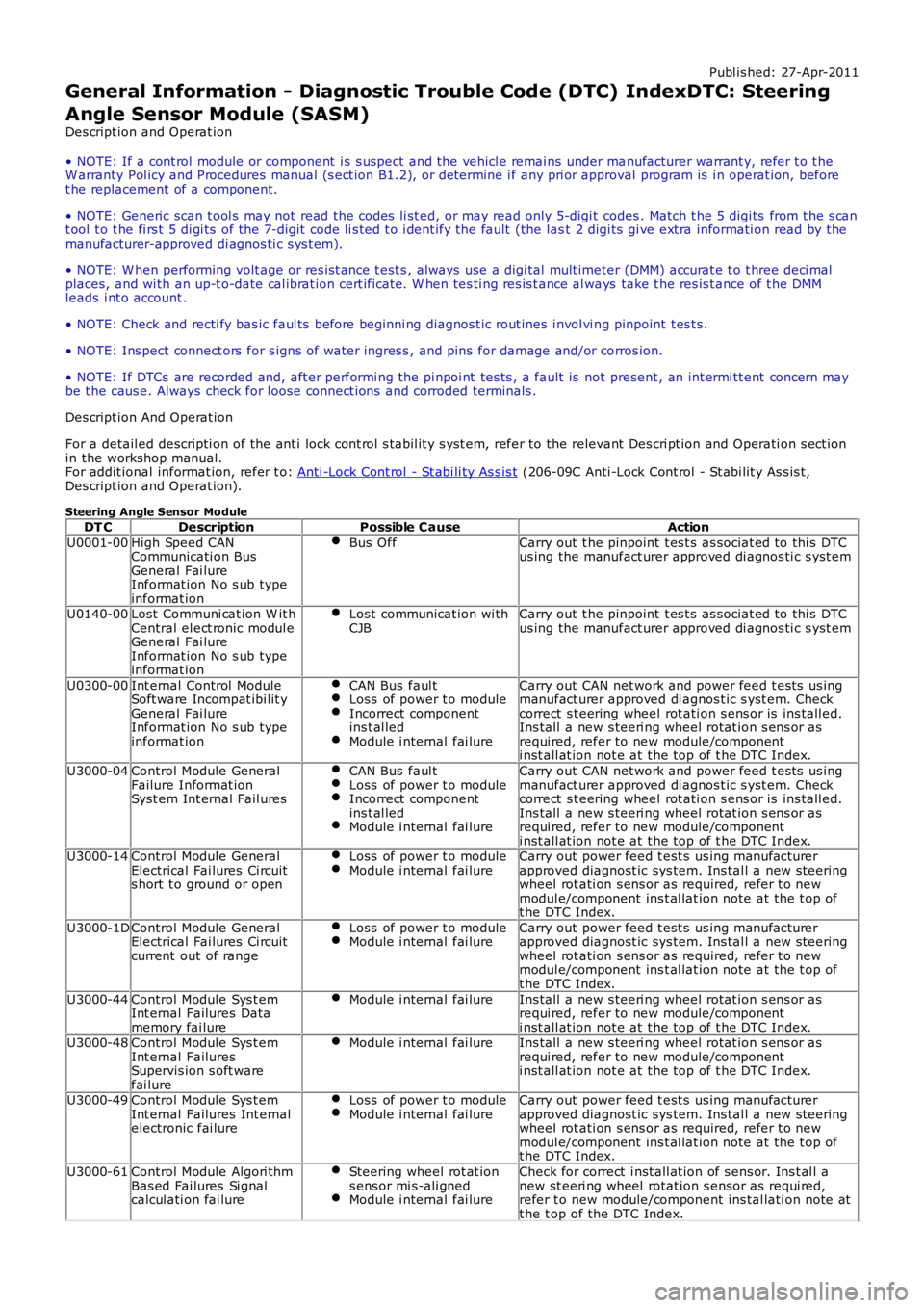
Publ is hed: 27-Apr-2011
General Information - Diagnostic Trouble Code (DTC) IndexDTC: Steering
Angle Sensor Module (SASM)
Des cript ion and Operat ion
• NOTE: If a cont rol module or component i s s uspect and the vehicl e remai ns under manufacturer warrant y, refer t o t heW arranty Pol icy and Procedures manual (s ect ion B1.2), or determine i f any pri or approval program is i n operat ion, beforet he replacement of a component.
• NOTE: Generic scan t ool s may not read the codes li st ed, or may read only 5-digi t codes . Match t he 5 digi ts from t he s cant ool t o t he fi rs t 5 di gi ts of the 7-digit code li s ted t o i dent ify the fault (the last 2 digi ts gi ve ext ra informati on read by themanufacturer-approved di agnos ti c s ys t em).
• NOTE: W hen performing volt age or res is t ance t est s , always use a digi tal mult imeter (DMM) accurat e t o t hree deci malplaces, and wi th an up-t o-date cal ibrat ion cert ificate. W hen tes ti ng res is t ance al ways take t he res is t ance of t he DMMleads i nt o account .
• NOTE: Check and recti fy bas ic faul ts before beginni ng diagnos t ic rout ines i nvol vi ng pinpoint t es t s.
• NOTE: Ins pect connect ors for s igns of water ingres s , and pins for damage and/or corros ion.
• NOTE: If DTCs are recorded and, aft er performi ng the pi npoi nt tes ts , a fault is not present , an int ermi tt ent concern maybe t he caus e. Always check for loose connect ions and corroded terminals .
Des cript ion And Operat ion
For a detail ed descripti on of the ant i lock cont rol s tabil it y s yst em, refer to the relevant Des cri pt ion and Operati on s ect ionin the workshop manual.For addit ional informat ion, refer t o: Anti -Lock Cont rol - St abi li ty As s is t (206-09C Anti -Lock Cont rol - St abi lit y As s is t,Des cript ion and Operat ion).
Steering Angle Sensor Module
DT CDescriptionPossible CauseAction
U0001-00High Speed CANCommunicati on BusGeneral Fai lureInformat ion No s ub typeinformat ion
Bus OffCarry out t he pinpoint t es t s as sociat ed to thi s DTCus ing the manufact urer approved di agnos ti c s yst em
U0140-00Lost Communi cat ion W it hCentral el ect ronic modul eGeneral Fai lureInformat ion No s ub typeinformat ion
Lost communicat ion wi thCJBCarry out t he pinpoint t es t s as sociat ed to thi s DTCus ing the manufact urer approved di agnos ti c s yst em
U0300-00Int ernal Control ModuleSoft ware Incompat ibi lit yGeneral Fai lureInformat ion No s ub typeinformat ion
CAN Bus faul tLoss of power t o moduleIncorrect componentins t al ledModule i nternal fai lure
Carry out CAN net work and power feed t es ts us ingmanufact urer approved di agnos t ic s yst em. Checkcorrect s t eering wheel rot ati on s ens or is ins tall ed.Ins tall a new s teeri ng wheel rotat ion s ens or asrequi red, refer to new module/componenti nst all at ion not e at t he top of t he DTC Index.
U3000-04Control Module GeneralFailure Informat ionSyst em Int ernal Fail ures
CAN Bus faul tLoss of power t o moduleIncorrect componentins t al ledModule i nternal fai lure
Carry out CAN net work and power feed t es ts us ingmanufact urer approved di agnos t ic s yst em. Checkcorrect s t eering wheel rot ati on s ens or is ins tall ed.Ins tall a new s teeri ng wheel rotat ion s ens or asrequi red, refer to new module/componenti nst all at ion not e at t he top of t he DTC Index.U3000-14Control Module GeneralElectrical Fai lures Ci rcuits hort t o ground or open
Loss of power t o moduleModule i nternal fai lureCarry out power feed t est s us ing manufact urerapproved diagnost ic sys tem. Ins tal l a new s teeringwheel rot ati on s ens or as required, refer t o newmodul e/component ins t al lat ion note at the t op oft he DTC Index.
U3000-1DControl Module GeneralElectrical Fai lures Ci rcuitcurrent out of range
Loss of power t o moduleModule i nternal fai lureCarry out power feed t est s us ing manufact urerapproved diagnost ic sys tem. Ins tal l a new s teeringwheel rot ati on s ens or as required, refer t o newmodul e/component ins t al lat ion note at the t op oft he DTC Index.
U3000-44Control Module Sys t emInt ernal Failures Datamemory fai lure
Module i nternal fai lureIns tall a new s teeri ng wheel rotat ion s ens or asrequi red, refer to new module/componenti nst all at ion not e at t he top of t he DTC Index.U3000-48Control Module Sys t emInt ernal FailuresSupervis ion s oft warefai lure
Module i nternal fai lureIns tall a new s teeri ng wheel rotat ion s ens or asrequi red, refer to new module/componenti nst all at ion not e at t he top of t he DTC Index.
U3000-49Control Module Sys t emInt ernal Failures Int ernalelectronic fai lure
Loss of power t o moduleModule i nternal fai lureCarry out power feed t est s us ing manufact urerapproved diagnost ic sys tem. Ins tal l a new s teeringwheel rot ati on s ens or as required, refer t o newmodul e/component ins t al lat ion note at the t op oft he DTC Index.
U3000-61Control Module Algori thmBas ed Fai lures Si gnalcalcul ati on fai lure
Steering wheel rot at ions ens or mi s-ali gnedModule i nternal fai lure
Check for correct i nst all at ion of s ens or. Ins t al l anew st eeri ng wheel rotat ion s ensor as requi red,refer t o new module/component ins tal lati on note att he t op of the DTC Index.
Page 139 of 3229
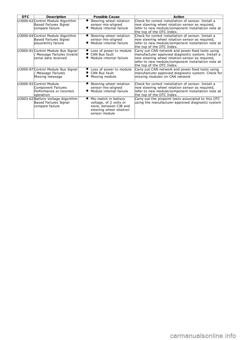
DT CDescriptionPossible CauseAction
U3000-62Control Module Algori thmBas ed Fai lures Si gnalcompare failure
Steering wheel rot at ions ens or mi s-ali gnedModule i nternal fai lure
Check for correct i nst all at ion of s ens or. Ins t al l anew st eeri ng wheel rotat ion s ensor as requi red,refer t o new module/component ins tal lati on note att he t op of the DTC Index.U3000-64Control Module Algori thmBas ed Fai lures Si gnalplaus ibil it y fai lure
Steering wheel rot at ions ens or mi s-ali gnedModule i nternal fai lure
Check for correct i nst all at ion of s ens or. Ins t al l anew st eeri ng wheel rotat ion s ensor as requi red,refer t o new module/component ins tal lati on note att he t op of the DTC Index.U3000-81Control Module Bus Signal/ Mes s age Fai lures Inval ids eri al dat a received
Loss of power t o moduleCAN Bus faul tModule i nternal fai lure
Carry out CAN net work and power feed t es ts us ingmanufact urer approved di agnos t ic s yst em. Ins t all anew st eeri ng wheel rotat ion s ensor as requi red,refer t o new module/component ins tal lati on note att he t op of the DTC Index.
U3000-87Control Module Bus Signal/ Mes s age Fai luresMi ss ing mess age
Loss of power t o moduleCAN Bus faul tMis s ing modul e
Carry out CAN net work and power feed t es ts us ingmanufact urer approved di agnos t ic s yst em. Check formis s ing modules on CAN network
U3000-92Control ModuleComponent Fail uresPerformance or incorrectoperati on
Steering wheel rot at ions ens or mi s-ali gnedModule i nternal fai lure
Check for correct i nst all at ion of s ens or. Ins t al l anew st eeri ng wheel rotat ion s ensor as requi red,refer t o new module/component ins tal lati on note att he t op of the DTC Index.U3003-62Batt ery Vol tage Al gorit hmBas ed Fai lures Si gnalcompare failure
Mis -match i n batt eryvolt age, of 2 volt s ormore, bet ween CJB ands teeri ng wheel rotat ions ens or module
Carry out t he pinpoint t es t s as sociat ed to thi s DTCus ing the manufact urer approved di agnos ti c s yst em
Page 163 of 3229
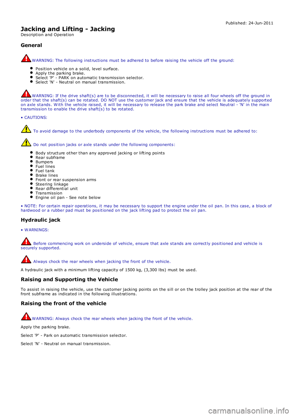
Publ is hed: 24-Jun-2011
Jacking and Lifting - Jacking
Des cript ion and Operat ion
General
W ARNING: The foll owing i nst ructi ons mus t be adhered to before rais i ng the vehicle off t he ground:
Posi ti on vehi cl e on a sol id, level surface.Apply t he parking brake.Select 'P' - PARK on automat ic t rans mis s ion sel ect or.Select 'N' - Neutral on manual t rans mis s ion.
W ARNING: If t he dri ve s haft(s ) are t o be di sconnect ed, i t wil l be neces s ary t o rai s e all four wheels off the ground inorder t hat t he s haft (s ) can be rot ated. DO NOT us e the cus tomer jack and ens ure that t he vehi cl e is adequatel y s upport edon axle s t ands . W i th the vehicle rai sed, it will be necess ary to releas e t he park brake and sel ect Neutral - 'N' in the mai nt ransmis s ion t o enabl e t he dri ve s haft(s ) to be rot ated.
• CAUTIO NS:
To avoid damage t o t he underbody components of t he vehi cle, the foll owing i ns t ructions mus t be adhered to:
Do not pos it ion jacks or axle s t ands under the foll owing component s :
Body s truct ure ot her t han any approved jacki ng or li ft ing point sRear subframeBumpersFuel l inesFuel t ankBrake l inesFront or rear s uspens ion armsSteering l inkageRear di fferenti al uni tTrans mis s ionEngi ne oil pan - See not e below
• NOTE: For certain repair operat ions, i t may be necess ary to support t he engine under t he oil pan. In thi s cas e, a bl ock ofhardwood or a rubber pad mus t be pos it ioned on t he jack li ft ing pad t o protect the oi l pan.
Hydraulic jack
• W ARNINGS:
Before commenci ng work on undersi de of vehi cl e, ens ure that axle s t ands are correctly pos it ioned and vehi cle i ss ecurel y s upported.
Al ways chock the rear wheel s when jacking t he front of the vehicle.
A hydrauli c jack wi th a mi ni mum li ft ing capacit y of 1500 kg, (3,300 l bs) must be us ed.
Raising and Supporting the Vehicle
To as si s t in rais ing the vehicle, us e t he cus t omer jacki ng poi nts on the s i ll or on t he trolley jack pos i ti on at the rear of t hefront subframe as indicated i n t he fol lowing ill ust rat ions .
Raising the front of the vehicle
W ARNING: Always chock t he rear wheels when jacki ng the front of t he vehi cl e.
Apply t he parking brake.
Select 'P' - Park on aut omat ic trans mi s si on s el ect or.
Select 'N' - Neutral on manual t rans mis s ion.