2006 LAND ROVER FRELANDER 2 wheel alignment
[x] Cancel search: wheel alignmentPage 194 of 3229
Publ is hed: 08-Dec-2011
Suspension System - General Information -
C oil Spring SuspensionItemSpecification
FrontFront: - Convent ional coi l spring wi th a t win tube damper and a high s t res s s tabi lizer bar
RearRear: - Convent ional coil s pri ng wit h a twi n t ube damper and a hi gh s tress st abil izer bar
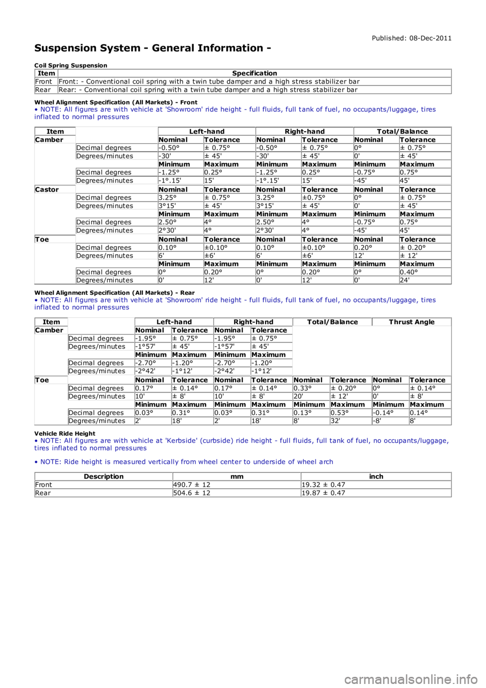
Wheel Alignment Specification (All Markets) - Front• NOTE: All figures are wi th vehicle at 'Showroom' ri de height - ful l flui ds, full tank of fuel , no occupants /l uggage, ti resinflat ed to normal pres sures
ItemLeft-handRight-handT otal/Balance
CamberNominalT oleranceNominalT oleranceNominalT oleranceDeci mal degrees-0.50°± 0.75°-0.50°± 0.75°0°± 0.75°
Degrees/mi nut es-30'± 45'-30'± 45'0'± 45'
MinimumMaximumMinimumMaximumMinimumMaximumDeci mal degrees-1.25°0.25°-1.25°0.25°-0.75°0.75°
Degrees/mi nut es-1°.15'15'-1°.15'15'-45'45'
CastorNominalT oleranceNominalT oleranceNominalT oleranceDeci mal degrees3.25°± 0.75°3.25°±0.75°0°± 0.75°
Degrees/mi nut es3°15'± 45'3°15'± 45'0'± 45'
MinimumMaximumMinimumMaximumMinimumMaximumDeci mal degrees2.50°4°2.50°4°-0.75°0.75°
Degrees/mi nut es2°30'4°2°30'4°-45'45'
T oeNominalT oleranceNominalT oleranceNominalT olerance
Deci mal degrees0.10°±0.10°0.10°±0.10°0.20°± 0.20°Degrees/mi nut es6'±6'6'±6'12'± 12'
MinimumMaximumMinimumMaximumMinimumMaximum
Deci mal degrees0°0.20°0°0.20°0°0.40°Degrees/mi nut es0'12'0'12'0'24'
Wheel Alignment Specification (All Markets) - Rear• NOTE: All figures are wi th vehicle at 'Showroom' ri de height - ful l flui ds, full tank of fuel , no occupants /l uggage, ti resinflat ed to normal pres sures
ItemLeft-handRight-handT otal/BalanceT hrust Angle
CamberNominalT oleranceNominalT olerance
Deci mal degrees-1.95°± 0.75°-1.95°± 0.75°Degrees /mi nut es-1°57'± 45'-1°57'± 45'
MinimumMaximumMinimumMaximum
Deci mal degrees-2.70°-1.20°-2.70°-1.20°Degrees /mi nut es-2°42'-1°12'-2°42'-1°12'
T oeNominalT oleranceNominalT oleranceNominalT oleranceNominalT olerance
Deci mal degrees0.17°± 0.14°0.17°± 0.14°0.33°± 0.20°0°± 0.14°Degrees /mi nut es10'± 8'10'± 8'20'± 12'0'± 8'
MinimumMaximumMinimumMaximumMinimumMaximumMinimumMaximum
Deci mal degrees0.03°0.31°0.03°0.31°0.13°0.53°-0.14°0.14°Degrees /mi nut es2'18'2'18'8'32'-8'8'
Vehicle Ride Height• NOTE: All figures are wi th vehicle at 'Kerbs ide' (curbs ide) ride height - ful l fl uids , full t ank of fuel, no occupants /luggage,t ires infl ated t o normal press ures
• NOTE: Ride hei ght i s meas ured vert icall y from wheel cent er to unders i de of wheel arch
Descriptionmminch
Front490.7 ± 1219.32 ± 0.47
Rear504.6 ± 1219.87 ± 0.47
Page 196 of 3229
Publi s hed: 11-May-2011
Suspension System - General Information - Four-Wheel Alignment
General Procedures
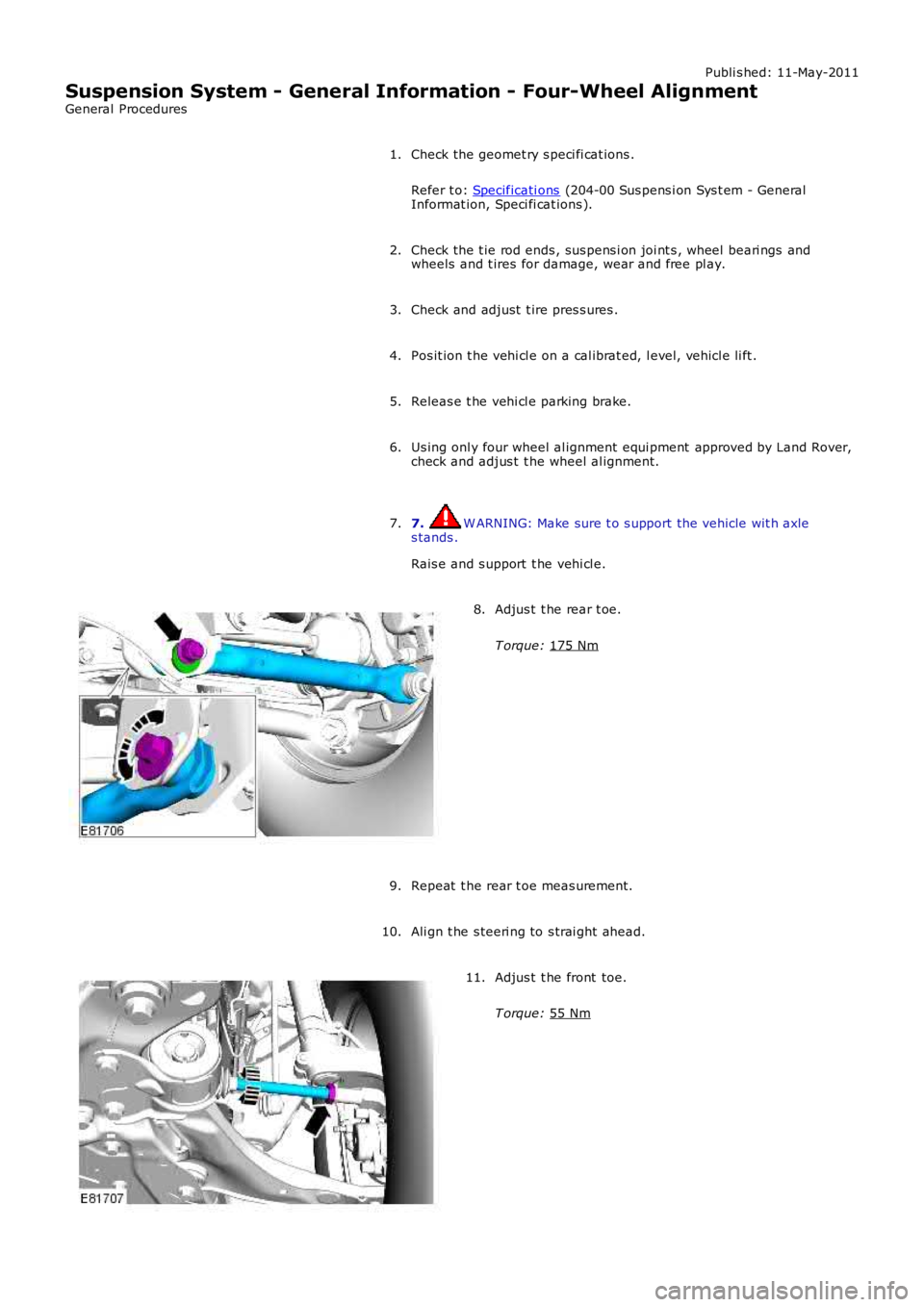
Check the geomet ry s peci fi cat ions .
Refer t o: Specificati ons (204-00 Sus pens i on Sys t em - GeneralInformat ion, Speci fi cat ions ).
1.
Check the t ie rod ends , sus pens i on joi nt s , wheel beari ngs andwheels and t ires for damage, wear and free pl ay.2.
Check and adjust t ire pres s ures .3.
Pos it ion t he vehi cl e on a cal ibrat ed, l evel , vehicl e li ft .4.
Releas e t he vehi cl e parking brake.5.
Us ing onl y four wheel al ignment equi pment approved by Land Rover,check and adjus t t he wheel al ignment.6.
7. W ARNING: Make sure t o s upport the vehicle wit h axles tands .
Rais e and s upport t he vehi cl e.
7.
Adjus t t he rear t oe.
T orque: 175 Nm
8.
Repeat t he rear t oe meas urement.9.
Ali gn t he s teeri ng to s trai ght ahead.10.
Adjus t t he front toe.
T orque: 55 Nm
11.
Page 302 of 3229
Bearing Rumbl e
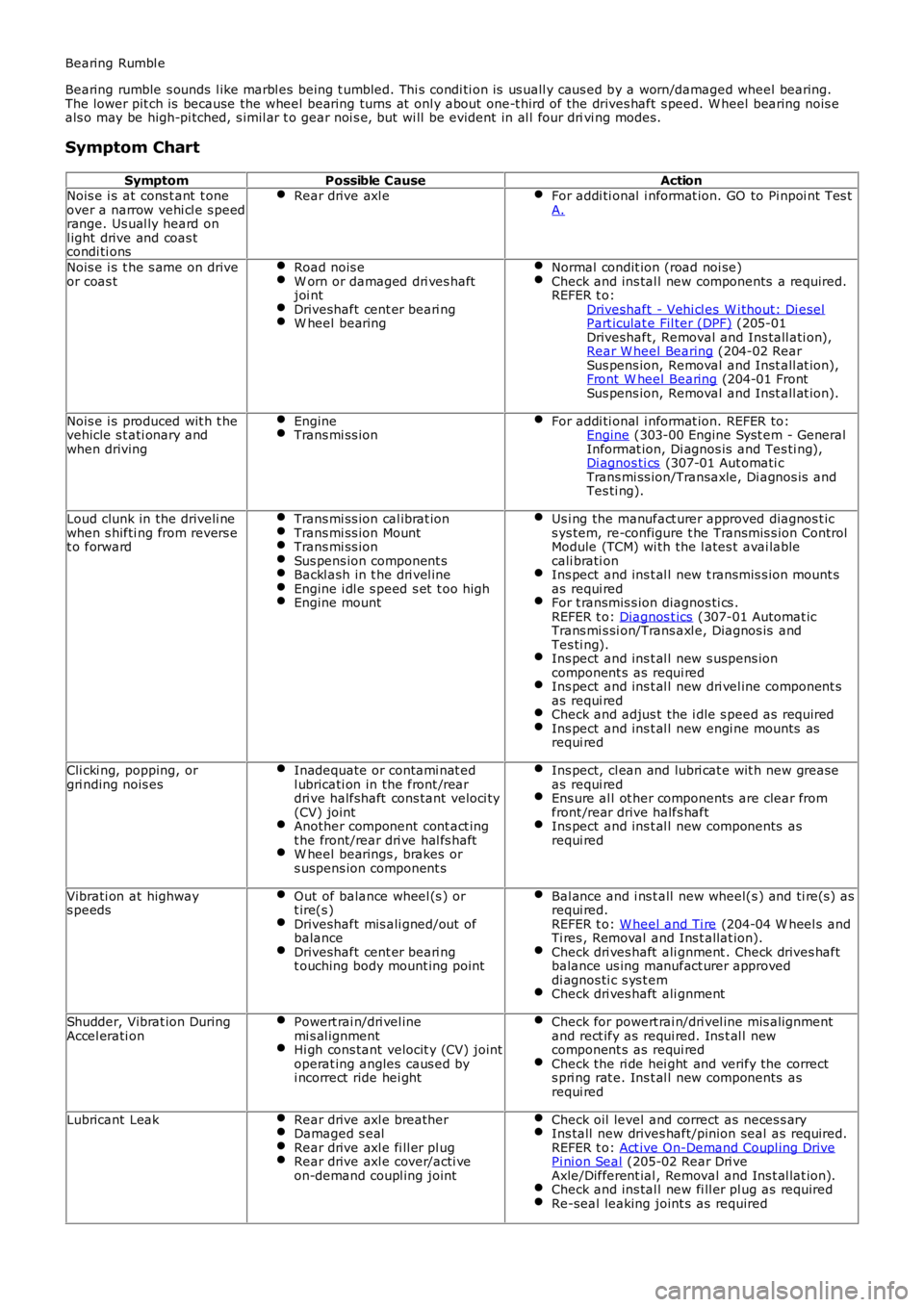
Bearing rumble s ounds l ike marbl es being t umbled. Thi s condi ti on is us uall y caus ed by a worn/damaged wheel bearing.The lower pit ch is because the wheel bearing turns at onl y about one-t hird of the drives haft s peed. W heel bearing nois eals o may be high-pi tched, s imil ar t o gear noi s e, but wi ll be evident in al l four drivi ng modes.
Symptom Chart
SymptomPossible CauseActionNois e i s at cons t ant t oneover a narrow vehi cl e s peedrange. Us ual ly heard onl ight drive and coas tcondi ti ons
Rear drive axl eFor addi ti onal i nformat ion. GO to Pi npoi nt Tes tA.
Nois e i s t he s ame on driveor coas tRoad nois eW orn or damaged dri ves haftjoi ntDriveshaft cent er beari ngW heel bearing
Normal condit ion (road noi se)Check and ins tal l new components a required.REFER t o:Driveshaft - Vehi cl es W i thout: Di eselPart iculat e Fil ter (DPF) (205-01Driveshaft, Removal and Ins tall ati on),Rear W heel Bearing (204-02 RearSus pens ion, Removal and Inst all at ion),Front W heel Bearing (204-01 FrontSus pens ion, Removal and Inst all at ion).
Nois e i s produced wit h t hevehicle s t ati onary andwhen driving
EngineTrans mi ss ionFor addi ti onal i nformat ion. REFER to:Engine (303-00 Engine Syst em - GeneralInformat ion, Di agnos is and Tes ti ng),Di agnos ti cs (307-01 Aut omati cTrans mi ss ion/Transaxle, Di agnos is andTes ti ng).
Loud clunk in the driveli newhen s hifti ng from revers et o forward
Trans mi ss ion cal ibrat ionTrans mi ss ion MountTrans mi ss ionSus pens ion component sBackl ash in t he dri vel ineEngine i dl e s peed s et t oo highEngine mount
Us i ng the manufact urer approved diagnos t ics ys tem, re-configure t he Transmis s ion ControlModule (TCM) wi th the l ates t avai lablecali brati onIns pect and ins t al l new t ransmis s ion mount sas requi redFor t ransmis s ion diagnos ti cs .REFER t o: Diagnos t ics (307-01 Automat icTrans mi s si on/Trans axl e, Diagnos is andTes ti ng).Ins pect and ins t al l new s uspens ioncomponent s as requi redIns pect and ins t al l new dri vel ine component sas requi redCheck and adjus t the i dle s peed as requi redIns pect and ins t al l new engi ne mounts asrequi red
Cli cki ng, popping, orgri nding nois esInadequate or contami nat edl ubricati on in the front /reardri ve halfshaft cons tant veloci ty(CV) jointAnother component cont act ingt he front/rear dri ve hal fs haftW heel bearings , brakes ors uspens ion component s
Ins pect, cl ean and lubri cat e wit h new greaseas requi redEns ure al l ot her components are clear fromfront /rear drive halfs haftIns pect and ins t al l new components asrequi red
Vibrati on at highways peedsOut of balance wheel (s ) ort ire(s )Driveshaft mis ali gned/out ofbalanceDriveshaft cent er beari ngt ouching body mount ing point
Bal ance and i ns t all new wheel(s ) and ti re(s) asrequi red.REFER t o: W heel and Ti re (204-04 W heel s andTi res , Removal and Ins t allat ion).Check dri ves haft ali gnment . Check drives haftbalance us ing manufact urer approveddi agnos ti c s ys t emCheck dri ves haft ali gnment
Shudder, Vibrat ion DuringAccel erati onPowert rai n/dri vel inemi s al ignmentHi gh cons tant velocit y (CV) jointoperat ing angles caus ed byi ncorrect ride hei ght
Check for powert rai n/dri vel ine mis alignmentand rect ify as requi red. Ins t al l newcomponent s as requi redCheck the ri de hei ght and verify the corrects pri ng rat e. Ins t al l new components asrequi red
Lubricant LeakRear drive axl e breatherDamaged s ealRear drive axl e fi ll er pl ugRear drive axl e cover/acti veon-demand coupl ing joint
Check oil level and correct as neces s aryIns tall new drives haft/pinion seal as required.REFER t o: Act ive On-Demand Coupl ing DrivePi ni on Seal (205-02 Rear Dri veAxle/Different ial , Removal and Ins t al lat ion).Check and ins tal l new fi ll er pl ug as requiredRe-seal leaking joint s as required
Page 412 of 3229
1
1
1
1
2
3
4
5
6
7
1
1
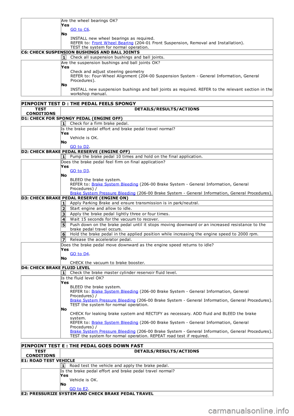
Are the wheel bearings OK?YesGO to C6.NoINSTALL new wheel bearings as requi red.REFER to: Front W heel Beari ng (204-01 Front Sus pensi on, Removal and Ins t al lat ion).TEST t he sys t em for normal operat ion.
C6: CHECK SUSPENSION BUSHINGS AND BALL JOINT S
Check al l s us pensi on bushi ngs and bal l joint s.
Are the s us pens ion bus hings and ball joints OK?YesCheck and adjust s t eering geomet ryREFER to: Four-W heel Alignment (204-00 Suspens ion Sys tem - General Informati on, GeneralProcedures ).NoINSTALL new sus pens i on bus hings and ball joints as required. REFER t o t he rel evant sect ion i n t heworks hop manual.
PINPOINT TEST D : THE PEDAL FEELS SPONG Y
T ESTCONDIT IO NSDET AILS/RESULT S/ACT IO NS
D1: CHECK FOR SPONGY PEDAL (ENGINE OFF)
Check for a fi rm brake pedal.
Is t he brake pedal effort and brake pedal t ravel normal?YesVehi cl e i s OK.NoGO t o D2.
D2: CHECK BR AKE PEDAL RESERVE (ENGINE OFF)Pump t he brake pedal 10 t imes and hol d on t he final appli cat ion.
Does t he brake pedal feel fi rm on final appl icat ion?YesGO t o D3.NoBLEED the brake sys tem.REFER t o: Brake Sys tem Bleeding (206-00 Brake Sys tem - General Informat ion, GeneralProcedures ) /Brake Syst em Press ure Bleeding (206-00 Brake Sys tem - General Informat ion, General Procedures ).D3: CHECK BR AKE PEDAL RESERVE (ENGINE ON)
Appl y Parking Brake and ens ure transmis s ion i s in park/neutral .
Start engine and al low to idle.
Appl y t he brake pedal l ightl y t hree or four t imes .
W ait 15 seconds for t he vacuum t o recover.
Pus h down on the brake pedal unti l it s tops movi ng downward or an increas ed res i st ance to t hebrake pedal t ravel occurs .Hold t he brake pedal in t he applied pos it ion whi le increasi ng t he engi ne s peed t o 2000 rpm.
Rel ease the accel erat or pedal.
Does t he brake pedal move downward as t he engine s peed ret urns t o idl e?YesGO t o D4.NoCHECK the vacuum t o brake boos ter.
D4: CHECK BR AKE FLUID LEVELCheck t he brake mas t er cyli nder reservoi r fl ui d l evel.
Is t he fluid level OK?YesBLEED the brake sys tem.REFER t o: Brake Sys tem Bleeding (206-00 Brake Sys tem - General Informat ion, GeneralProcedures ) /Brake Syst em Press ure Bleeding (206-00 Brake Sys tem - General Informat ion, General Procedures ).TEST the s ys tem for normal operat ion.NoCHECK for l eaking brake s ys t em and RECTIFY as necess ary. ADD fl ui d and BLEED t he brakesys t em.REFER t o: Brake Sys tem Bleeding (206-00 Brake Sys tem - General Informat ion, GeneralProcedures ) /Brake Syst em Press ure Bleeding (206-00 Brake Sys tem - General Informat ion, General Procedures ).TEST the s ys tem for normal operat ion. REPEAT road tes t i f required.
PINPOINT TEST E : THE PEDAL GOES DOWN FAST
T ESTCONDIT IO NSDET AILS/RESULT S/ACT IONS
E1: ROAD T EST VEHICLE
Road t es t the vehicle and appl y the brake pedal .
Is t he brake pedal effort and brake pedal t ravel normal?YesVehi cl e is OK.NoGO t o E2.E2: PRESSURIZE SYST EM AND CHECK BRAKE PEDAL T RAVEL
Page 528 of 3229
Publi s hed: 11-May-2011
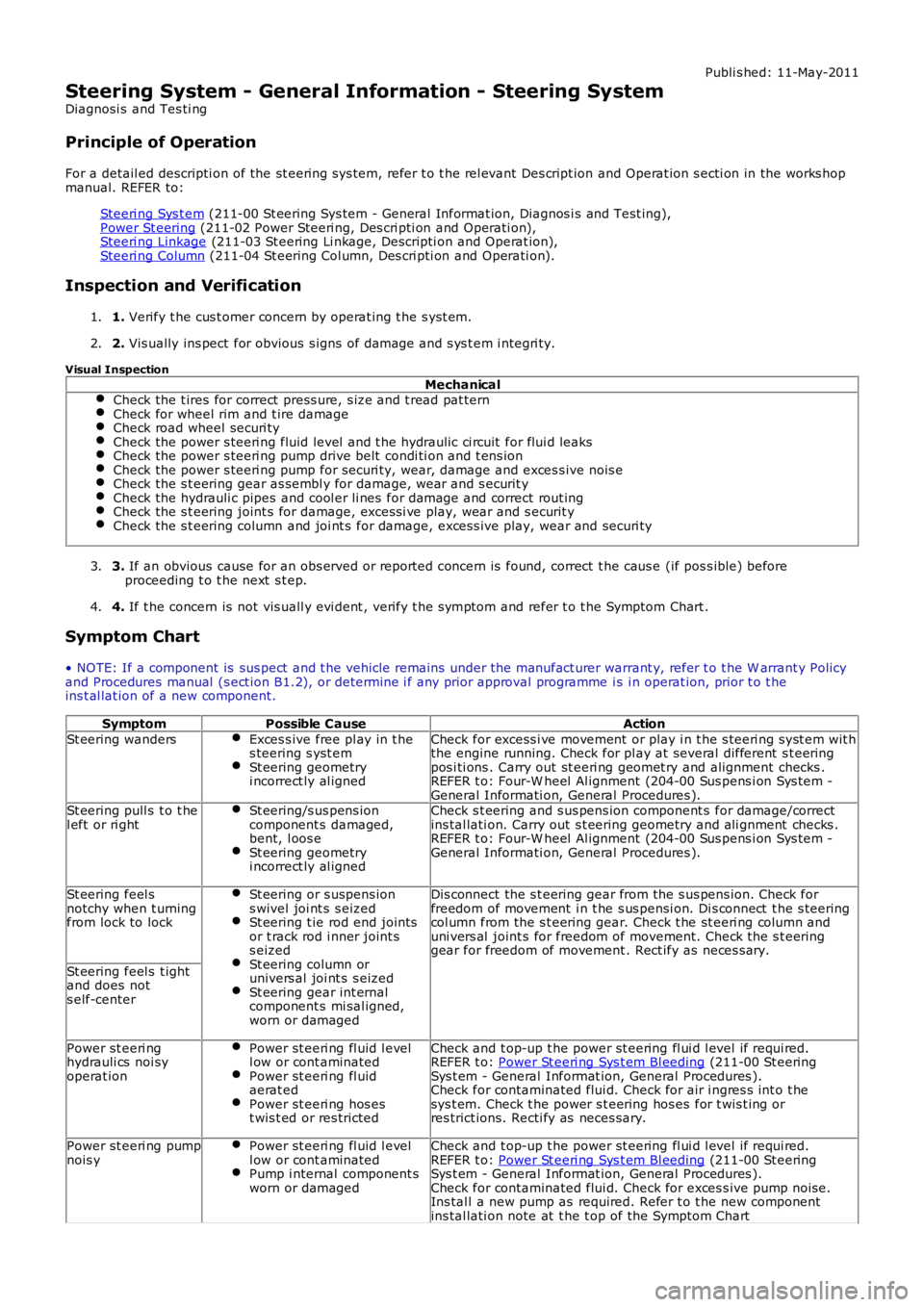
Steering System - General Information - Steering System
Diagnosi s and Tes ti ng
Principle of Operation
For a detail ed descripti on of the st eering sys tem, refer t o t he rel evant Des cript ion and Operat ion s ecti on in the works hopmanual. REFER to:
Steeri ng Sys t em (211-00 St eering Sys tem - General Informat ion, Diagnos i s and Test ing),Power St eering (211-02 Power Steeri ng, Des cri pti on and Operati on),Steeri ng Linkage (211-03 St eering Li nkage, Descripti on and Operat ion),Steeri ng Column (211-04 St eering Col umn, Des cri pti on and Operati on).
Inspection and Verification
1. Verify t he cus t omer concern by operat ing t he s yst em.1.
2. Vis ually ins pect for obvious s igns of damage and s ys t em i ntegri ty.2.
Visual Inspection
MechanicalCheck the t ires for correct press ure, s ize and t read pat ternCheck for wheel rim and t ire damageCheck road wheel securi tyCheck the power s teeri ng fluid level and t he hydraulic ci rcuit for flui d leaksCheck the power s teeri ng pump drive belt condi ti on and t ens ionCheck the power s teeri ng pump for securi ty, wear, damage and exces s ive nois eCheck the s t eering gear as sembl y for damage, wear and s ecurit yCheck the hydrauli c pipes and cool er li nes for damage and correct rout ingCheck the s t eering joint s for damage, excess i ve play, wear and s ecurit yCheck the s t eering column and joi nt s for damage, exces s ive play, wear and securi ty
3. If an obvious cause for an obs erved or report ed concern is found, correct t he caus e (if pos s ible) beforeproceeding t o t he next s t ep.3.
4. If t he concern is not vis uall y evi dent , verify t he s ymptom and refer t o t he Symptom Chart .4.
Symptom Chart
• NOTE: If a component is sus pect and t he vehicle remains under the manufact urer warrant y, refer t o t he W arrant y Policyand Procedures manual (s ect ion B1.2), or determine i f any prior approval programme is i n operat ion, prior t o t heins t al lat ion of a new component.
SymptomPossible CauseAction
St eering wandersExces s ive free pl ay in t hes teering s yst emSt eering geometryi ncorrect ly al igned
Check for excess i ve movement or play i n t he s teeri ng s yst em wit hthe engine running. Check for pl ay at several different s t eeringpos i ti ons . Carry out st eeri ng geomet ry and alignment checks .REFER t o: Four-W heel Al ignment (204-00 Sus pens i on Sys t em -General Informati on, General Procedures ).St eering pull s t o t hel eft or ri ghtSt eering/s us pens ioncomponent s damaged,bent, l oos eSt eering geometryi ncorrect ly al igned
Check s t eering and s us pens ion component s for damage/correctins tal lati on. Carry out s t eering geometry and ali gnment checks .REFER t o: Four-W heel Al ignment (204-00 Sus pens i on Sys t em -General Informati on, General Procedures ).
St eering feel snotchy when t urningfrom lock to lock
St eering or s uspens ions wivel joi nt s s eizedSt eering t ie rod end jointsor t rack rod i nner joint ss eizedSt eering column orunivers al joi nt s s eizedSt eering gear int ernalcomponent s mi sal igned,worn or damaged
Dis connect the s t eering gear from the s us pens ion. Check forfreedom of movement i n t he s us pensi on. Di s connect t he s teeringcol umn from the s t eering gear. Check t he st eeri ng col umn anduni vers al joint s for freedom of movement. Check the s t eeringgear for freedom of movement . Rect ify as neces s ary.
St eering feel s t ightand does nots elf-center
Power st eeri nghydrauli cs noi syoperat ion
Power st eeri ng fl uid l evell ow or cont aminatedPower st eeri ng fl uidaerat edPower st eeri ng hos est wis t ed or res tricted
Check and t op-up t he power st eering fl ui d l evel if requi red.REFER t o: Power St eeri ng Sys t em Bl eeding (211-00 St eeringSys t em - General Informat ion, General Procedures ).Check for contaminated flui d. Check for air i ngres s int o t hesys t em. Check t he power s t eering hos es for t wis t ing orres trict ions. Recti fy as neces sary.
Power st eeri ng pumpnois yPower st eeri ng fl uid l evell ow or cont aminatedPump i nternal component sworn or damaged
Check and t op-up t he power st eering fl ui d l evel if requi red.REFER t o: Power St eeri ng Sys t em Bl eeding (211-00 St eeringSys t em - General Informat ion, General Procedures ).Check for contaminated flui d. Check for exces s ive pump noi se.Ins tal l a new pump as required. Refer t o t he new componentins tal lati on note at t he t op of the Sympt om Chart
Page 2697 of 3229
Publ is hed: 11-May-2011
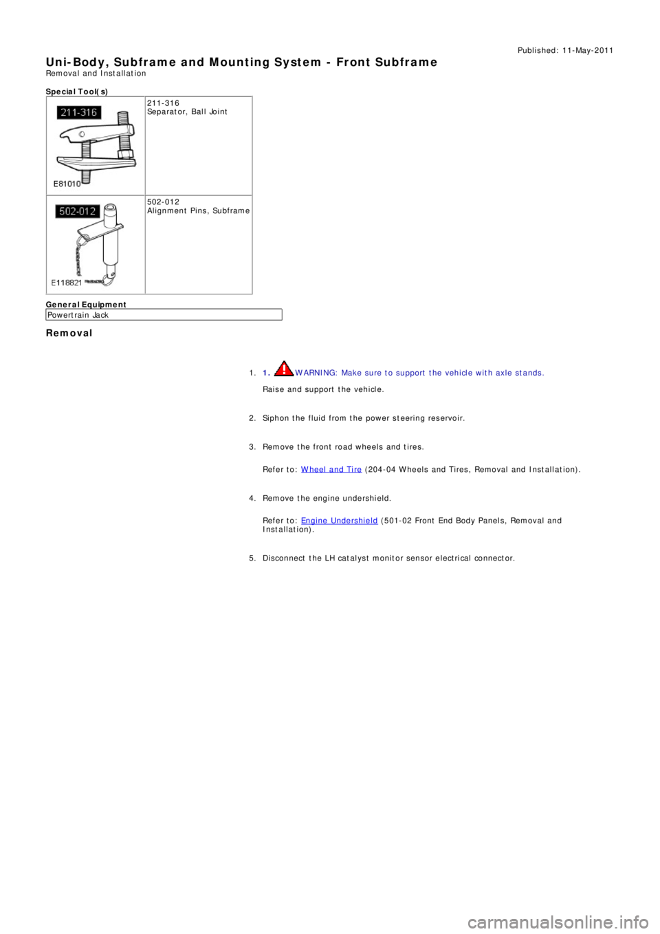
Uni-Body, Subframe and Mounting System - Front SubframeRemoval and Installation
S p e c ia l T o o l( s )
211-316
Se p a ra t o r, B a l l Jo i nt
502-012
Alignment Pins, Subframe
General Equipment
P o we rt ra i n Ja ck
Removal
1. WARNING: Make sure to support the vehicle with axle stands.
Raise and support the vehicle. 1.
Siphon the fluid from the power steering reservoir. 2.
Remove the front road wheels and tires.
Refer to: W heel and Tire
(204-04 W heels and Tires , Removal and Ins t all at i on). 3.
Remove the engine undershield.
Refer to: Engine Undershield
(501-02 Front End Body Panel s, Removal and
Installation). 4.
Di sconnect t he LH cat al ys t monit or sens or elect ri cal connect or. 5.
Page 2704 of 3229
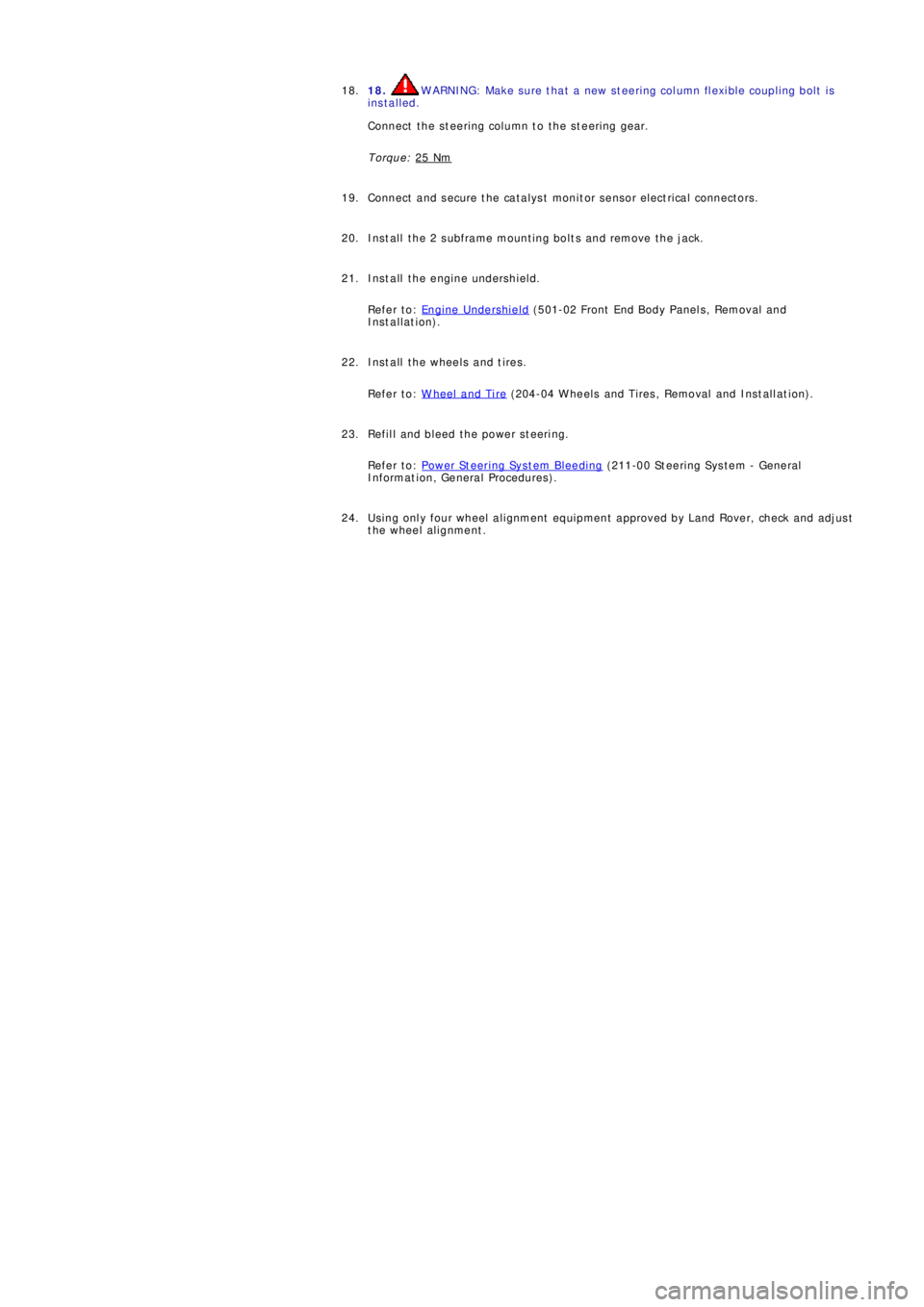
18. WARNING: Make sure that a new steering column flexible coupling bolt is
installed.
Connect the steering column to the steering gear.
Torque: 25 Nm18.
Connect and s ecure t he cat alys t moni t or s ens or el ect ri cal connect ors . 19.
Install the 2 subframe mounting bolts and remove the jack. 20.
Install the engine undershield.
Refer to: Engine Undershield
(501-02 Front End Body Panel s, Removal and
Installation). 21.
Install the wheels and tires.
Refer to: W heel and Tire
(204-04 W heels and Tires , Removal and Ins t all at i on). 22.
Refill and bleed the power steering.
Refer to: Power Steering System Bleeding
(211-00 St eeri ng Sys t em - General
Informat ion, General Procedures). 23.
Using only four wheel alignment equipment approved by Land Rover, check and adjust
the wheel alignment. 24.
Page 2717 of 3229
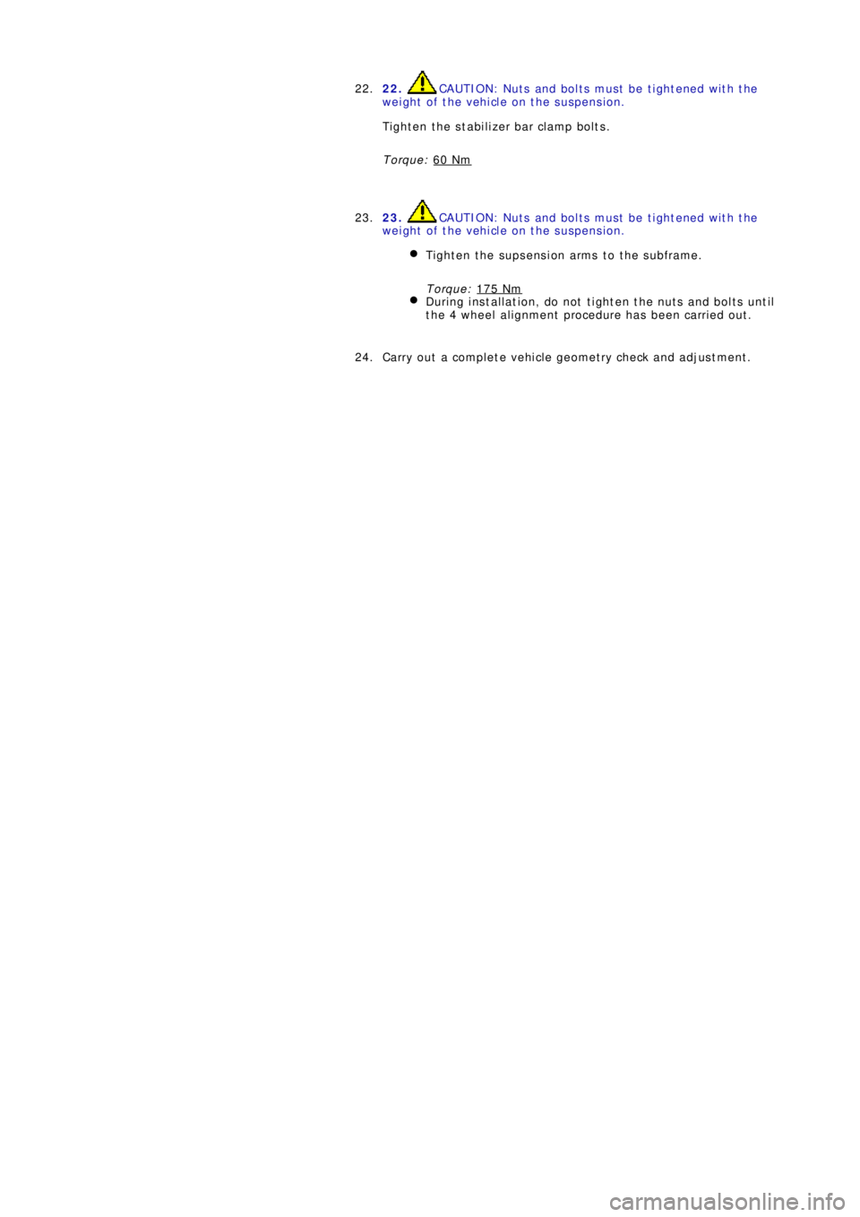
22. CAUTION: Nuts and bolts must be tightened with the
weight of the vehicle on the suspension.
Tighten the stabilizer bar clamp bolts.
Torque: 60 Nm22.
23.
CAUTION: Nuts and bolts must be tightened with the
weight of the vehicle on the suspension.
Tighten the supsension arms to the subframe.
Torque: 175 Nm
During installation, do not tighten the nuts and bolts until
the 4 wheel alignment procedure has been carried out.
23.
Carry out a complete vehicle geometry check and adjustment. 24.