2006 LAND ROVER FRELANDER 2 park assist
[x] Cancel search: park assistPage 123 of 3229
Publi s hed: 04-May-2011
General Information - Diagnostic Trouble Code (DTC) IndexDTC: Parking
Aid Module (PAM)
Des cript ion and Operat ion
• NOTE: If a cont rol module or component i s s uspect and the vehicl e remai ns under manufacturer warrant y, refer t o t heW arranty Pol icy and Procedures manual (s ect ion B1.2), or determine i f any pri or approval program is i n operat ion, beforet he replacement of a component.
• NOTE: Generic scan t ool s may not read the codes li st ed, or may read only 5-digi t codes . Match t he 5 digi ts from t he s cant ool t o t he fi rs t 5 di gi ts of the 7-digit code li s ted t o i dent ify the fault (the last 2 digi ts gi ve ext ra informati on read by themanufacturer-approved di agnos ti c s ys t em).
• NOTE: W hen performing volt age or res is t ance t est s , always use a digi tal mult imeter (DMM) accurat e t o t hree deci malplaces, and wi th an up-t o-date cal ibrat ion cert ificate. W hen tes ti ng res is t ance al ways take t he res is t ance of t he DMMleads i nt o account .
• NOTE: Check and recti fy bas ic faul ts before beginni ng diagnos t ic rout ines i nvol vi ng pinpoint t es t s.
• NOTE: Ins pect connect ors for s igns of water ingres s , and pins for damage and/or corros ion.
• NOTE: If DTCs are recorded and, aft er performi ng the pi npoi nt tes ts , a fault is not present , an int ermi tt ent concern maybe t he caus e. Always check for loose connect ions and corroded terminals .
Des cript ion And Operat ion
For a detail ed descripti on of the parki ng as si s t cont rol s ys t em, refer t o t he rel evant Des cript ion and Operat ion secti on int he works hop manual .For addit ional informat ion, refer t o: Parking Ai d (413-13 Parking Ai d, Des cri pti on and Operati on).
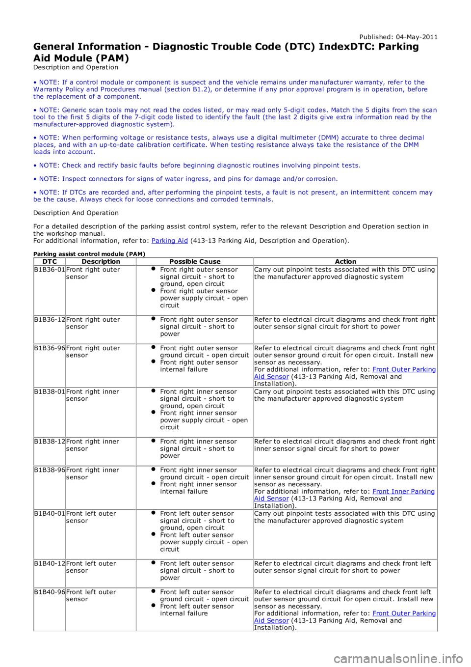
Parking assist control module (PAM)DT CDescriptionPossible CauseAction
B1B36-01Front ri ght out ers ens orFront ri ght out er sens ors ignal circui t - s hort t oground, open circui tFront ri ght out er sens orpower s upply circui t - openci rcuit
Carry out pinpoint t est s as s oci at ed wi th this DTC usi ngt he manufact urer approved di agnos ti c s ys t em
B1B36-12Front ri ght out ers ens orFront ri ght out er sens ors ignal circui t - s hort t opower
Refer to el ect ri cal circui t diagrams and check front rightout er sens or si gnal circui t for s hort t o power
B1B36-96Front ri ght out ers ens orFront ri ght out er sens orground circuit - open ci rcuitFront ri ght out er sens orint ernal fail ure
Refer to el ect ri cal circui t diagrams and check front rightout er sens or ground ci rcuit for open ci rcuit . Ins tal l news ens or as necess ary.For addit ional i nformati on, refer to: Front Out er ParkingAi d Sensor (413-13 Parking Ai d, Removal andIns tall ati on).
B1B38-01Front ri ght inners ens orFront ri ght i nner s ens ors ignal circui t - s hort t oground, open circui tFront ri ght i nner s ens orpower s upply circui t - openci rcuit
Carry out pinpoint t est s as s oci at ed wi th this DTC usi ngt he manufact urer approved di agnos ti c s ys t em
B1B38-12Front ri ght inners ens orFront ri ght i nner s ens ors ignal circui t - s hort t opower
Refer to el ect ri cal circui t diagrams and check front righti nner s ens or s i gnal circuit for s hort to power
B1B38-96Front ri ght inners ens orFront ri ght i nner s ens orground circuit - open ci rcuitFront ri ght i nner s ens orint ernal fail ure
Refer to el ect ri cal circui t diagrams and check front righti nner s ens or ground ci rcuit for open circui t. Ins tall news ens or as necess ary.For addit ional i nformati on, refer to: Front Inner Parki ngAi d Sensor (413-13 Parking Ai d, Removal andIns tall ati on).B1B40-01Front left out ers ens orFront left out er sens ors ignal circui t - s hort t oground, open circui tFront left out er sens orpower s upply circui t - openci rcuit
Carry out pinpoint t est s as s oci at ed wi th this DTC usi ngt he manufact urer approved di agnos ti c s ys t em
B1B40-12Front left out ers ens orFront left out er sens ors ignal circui t - s hort t opower
Refer to el ect ri cal circui t diagrams and check front l eftout er sens or si gnal circui t for s hort t o power
B1B40-96Front left out ers ens orFront left out er sens orground circuit - open ci rcuitFront left out er sens orint ernal fail ure
Refer to el ect ri cal circui t diagrams and check front l eftout er sens or ground ci rcuit for open ci rcuit . Ins tal l news ens or as necess ary.For addit ional i nformati on, refer to: Front Out er ParkingAi d Sensor (413-13 Parking Ai d, Removal andIns tall ati on).
Page 2844 of 3229

Brakes
124
L
ABS and off-road driving
ABS will operate when driving off-road,
however it may be unw ise to rely on it's
assistance under some conditions.
Stopping distances will be increased when
travelling over rough, or bumpy terrain.
Soft surfaces
On soft or deep surfaces such as powdery
snow, sand, or gravel, the braking distance
required will be increased. This is because the
natural action of a lock ed wheel (which cannot
happen when ABS is operating) is to form a
wedge of surface material in front of the wheel,
which reduces the stopping distance.
Steep slopes
If the vehicle is stationary on a steep, slippery
slope, it may begin to slide even with the
brakes applied. This is because without wheel
rotation the ABS cannot determine vehicle
movement.
To counteract this, briefl y release the brakes to
allow some wheel rota tion. Then re-apply the
brakes to allow ABS to gain control.
Emergency Brake Assist (EBA)
If the driver rapidly applies the brakes, EBA
automatically boosts the braking force to it's
maximum in order to bring the vehicle to a halt
as quickly as possible. If the driver applies the
brakes slowly, but condi tions mean that ABS
operates on the front wheels, EBA will increase
the braking force in order to apply ABS control
to the rear wheels.
EBA stops operating as soon as the brake pedal
is released.
A fault with the EBA system is
indicated by the red brake warning
indicator illuminating.
Electronic Brake Distribution (EBD)
EBD controls the balanc e of braking forces
supplied to the front and rear wheels, in order
to maintain maximum braking efficiency.
If the vehicle has a light load (only the driver in
the vehicle for example) the EBD will reduce the
braking force applied to the rear wheels. If the
vehicle is heavily laden then EBD will increase
the braking force to the rear wheels.
A fault with the EBD system is
indicated by the red brake warning
indicator illuminating.
PARKING BRAKE
Parking on a slope
Facing uphill
If the vehicle is parked facing uphill, select first
gear (manual gearbox), or Park (automatic
gearbox), and turn the steering wheel so that
the front wheels face away from the kerb.
Facing downhill
If the vehicle is parked facing downhill, select
reverse gear (manual gearbox), or Park
(automatic gearbox), and turn the steering
wheel so that the front wheels face towards the
kerb.
Page 2865 of 3229
145
Fuel and refuelling
R
REFUELLING
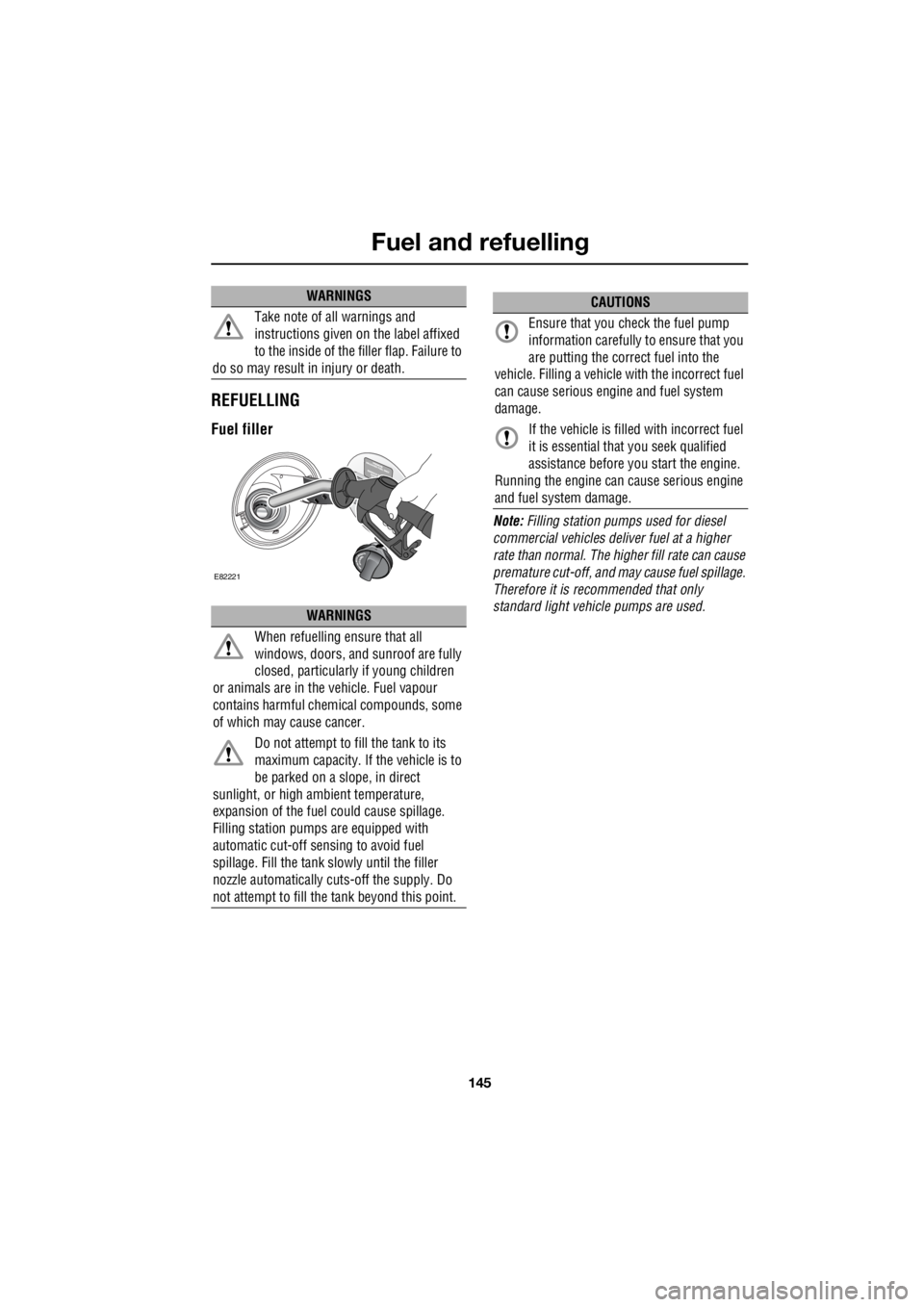
Fuel filler
Note: Filling station pumps used for diesel
commercial vehicles deliver fuel at a higher
rate than normal. The hi gher fill rate can cause
premature cut-off, and may cause fuel spillage.
Therefore it is recommended that only
standard light vehicle pumps are used.
Take note of all warnings and
instructions given on the label affixed
to the inside of the filler flap. Failure to
do so may result in injury or death.
WARNINGS
When refuelling ensure that all
windows, doors, and sunroof are fully
closed, particularly if young children
or animals are in the vehicle. Fuel vapour
contains harmful chem ical compounds, some
of which may cause cancer.
Do not attempt to fill the tank to its
maximum capacity. If the vehicle is to
be parked on a slope, in direct
sunlight, or high ambient temperature,
expansion of the fuel could cause spillage.
Filling station pumps are equipped with
automatic cut-off sensing to avoid fuel
spillage. Fill the tank sl owly until the filler
nozzle automatically cuts -off the supply. Do
not attempt to fill the tank beyond this point.
WARNINGS
E82221
CAUTIONS
Ensure that you check the fuel pump
information carefully to ensure that you
are putting the correct fuel into the
vehicle. Filling a vehicle with the incorrect fuel
can cause serious engi ne and fuel system
damage.
If the vehicle is filled with incorrect fuel
it is essential that you seek qualified
assistance before you start the engine.
Running the engine can cause serious engine
and fuel system damage.
Page 2891 of 3229
171
Vehicle battery
R
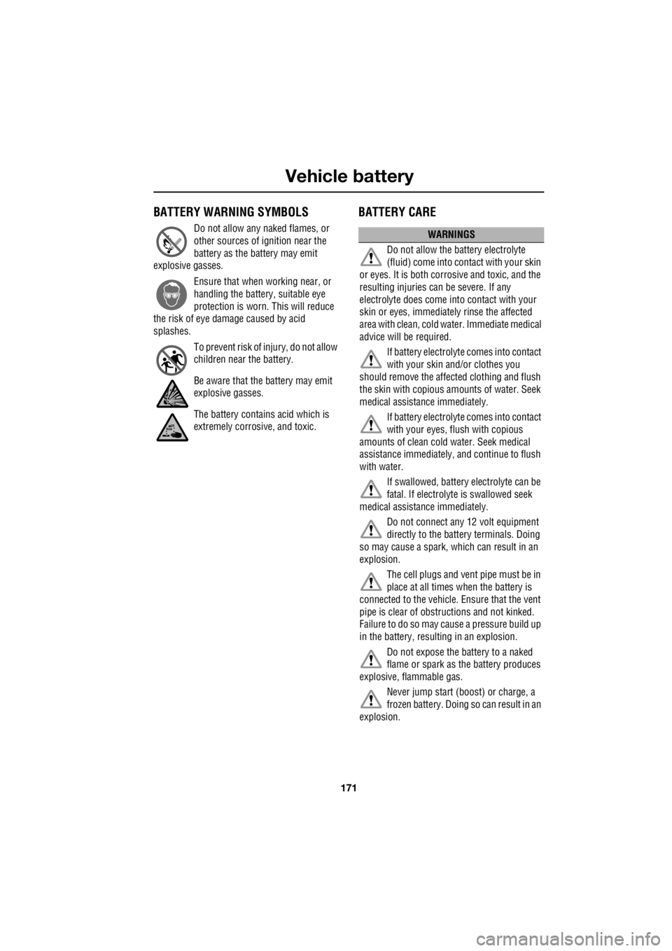
Vehicle batteryBATTERY WARNING SYMBOLS
Do not allow any naked flames, or
other sources of ignition near the
battery as the battery may emit
explosive gasses.
Ensure that when working near, or
handling the battery, suitable eye
protection is worn. This will reduce
the risk of eye dama ge caused by acid
splashes.
To prevent risk of injury, do not allow
children near the battery.
Be aware that the battery may emit
explosive gasses.
The battery contains acid which is
extremely corrosive, and toxic.
BATTERY CARE
WARNINGS
Do not allow the battery electrolyte
(fluid) come into contact with your skin
or eyes. It is both corrosive and toxic, and the
resulting injuries can be severe. If any
electrolyte does come into contact with your
skin or eyes, immediately rinse the affected
area with clean, cold water. Immediate medical
advice will be required.
If battery electrolyte comes into contact
with your skin and/or clothes you
should remove the affect ed clothing and flush
the skin with copious am ounts of water. Seek
medical assistance immediately.
If battery electrolyte comes into contact
with your eyes, flush with copious
amounts of clean cold water. Seek medical
assistance immediately, and continue to flush
with water.
If swallowed, battery electrolyte can be
fatal. If electrolyte is swallowed seek
medical assistance immediately.
Do not connect any 12 volt equipment
directly to the battery terminals. Doing
so may cause a spark, which can result in an
explosion.
The cell plugs and vent pipe must be in
place at all times when the battery is
connected to the vehicle. Ensure that the vent
pipe is clear of obstr uctions and not kinked.
Failure to do so may cause a pressure build up
in the battery, resulting in an explosion.
Do not expose the battery to a naked
flame or spark as the battery produces
explosive, flammable gas.
Never jump start (boost) or charge, a
frozen battery. Doing so can result in an
explosion.
Page 2895 of 3229
175
Vehicle battery
R
Effects of disconnecting
Disconnecting the battery can affect a number
of vehicle systems, especially if there is
insufficient battery power prior to
disconnection. For example, the alarm may
trigger depending on it's state when the battery
was disconnected. If the alarm does sound,
use the remote control in the normal way to
disarm the security system. The windows may
need resetting to enable the one-shot feature to
operate correctly. See ELECTRIC WINDOWS
(page 93).
Replacement batteries
Battery disposal
Note: Used batteries must be disposed of
correctly as they contain a number of harmful
substances. Seek advice on disposal from your
Land Rover Dealer/Authoris ed Repairer, and/or
your local authority.
Refitting
A new battery should be supplied with plastic
terminal covers. Leave the covers in place
when fitting the battery, and remove them one
at a time to fit the battery cable clamps.
Refitting is an exact reversal of the removal
procedure. If you are in any doubt about fitting
a battery seek qualified assistance before
attempting to fit the battery.
WARNING
Only fit a battery of the correct type and
rating. Fitting an in correct battery may
result in a fire, or damage to the electrical
system. If you are in any doubt when fitting a
battery seek qualified assistance.
WARNING
When refitting the battery ensure that
no metal objects , or vehicle
components, come into contact with the
battery terminals. Metal objects can cause a
spark or short circuit, both of which may result
in an explosion.
CAUTIONS
Ensure that when fitting a battery to the
vehicle, the terminals and battery clamps
are clean, and lightly coated with petroleum
jelly. This will ensure good electrical
connections are made, and help to prevent
corrosion.
Always follow the battery manufacturers
instructions. Failure to do so may result
in damage to the vehicl e and/or the electrical
system.
Page 2928 of 3229
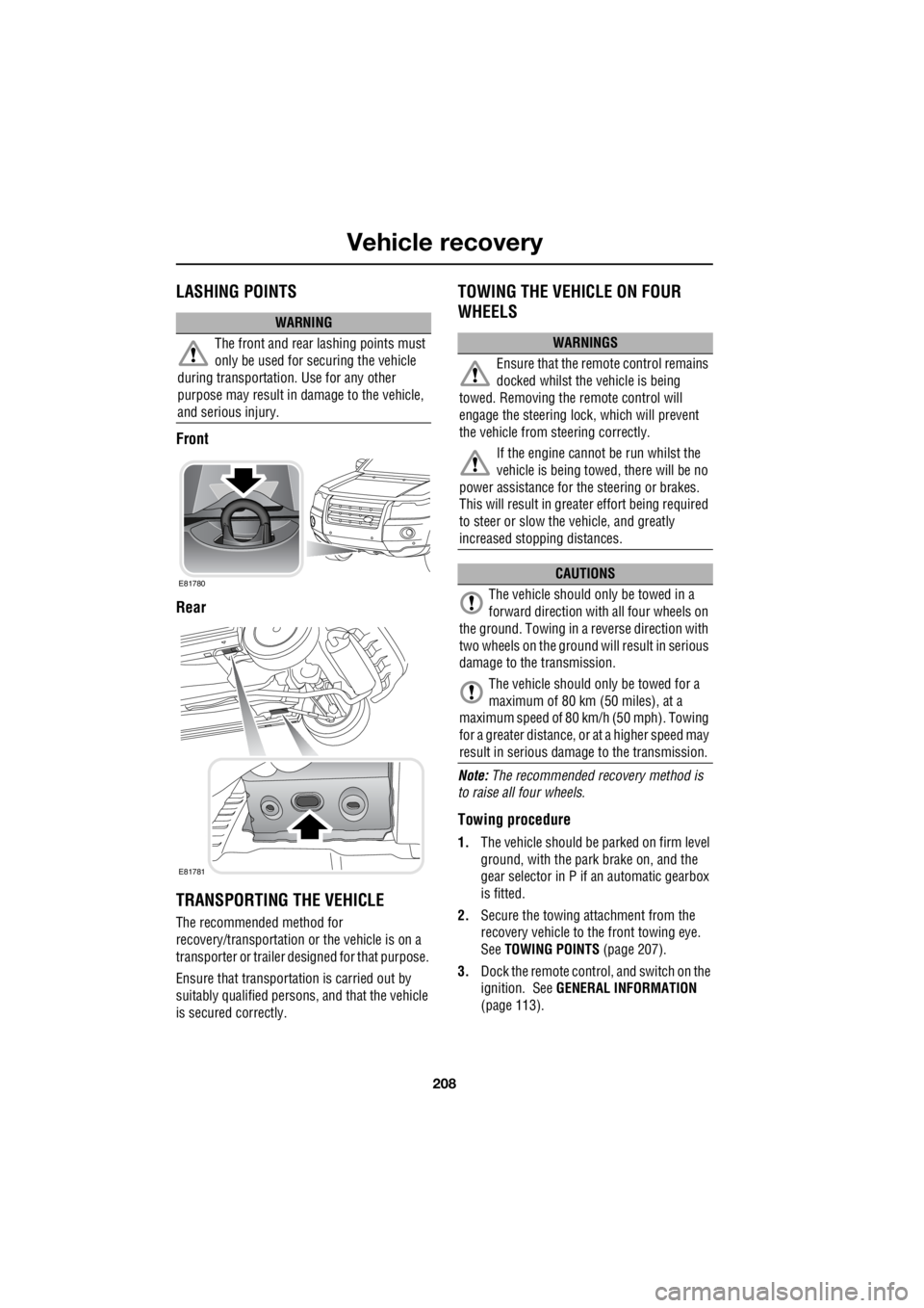
Vehicle recovery
208
L
LASHING POINTS
Front
Rear
TRANSPORTING THE VEHICLE
The recommended method for
recovery/transportation or the vehicle is on a
transporter or trailer de signed for that purpose.
Ensure that transporta tion is carried out by
suitably qualified persons , and that the vehicle
is secured correctly.
TOWING THE VEHICLE ON FOUR
WHEELS
Note: The recommended recovery method is
to raise all four wheels.
Towing procedure
1. The vehicle should be parked on firm level
ground, with the park brake on, and the
gear selector in P if an automatic gearbox
is fitted.
2. Secure the towing attachment from the
recovery vehicle to the front towing eye.
See TOWING POINTS (page 207).
3. Dock the remote control, and switch on the
ignition. See GENERAL INFORMATION
(page 113).
WARNING
The front and rear lashing points must
only be used for securing the vehicle
during transportation. Use for any other
purpose may result in da mage to the vehicle,
and serious injury.
E81780
E81781
WARNINGS
Ensure that the remote control remains
docked whilst the vehicle is being
towed. Removing the remote control will
engage the steering lo ck, which will prevent
the vehicle from steering correctly.
If the engine cannot be run whilst the
vehicle is being towed, there will be no
power assistance for the steering or brakes.
This will result in grea ter effort being required
to steer or slow the vehicle, and greatly
increased stopping distances.
CAUTIONS
The vehicle should only be towed in a
forward direction with all four wheels on
the ground. Towing in a reverse direction with
two wheels on the ground will result in serious
damage to the transmission.
The vehicle should only be towed for a
maximum of 80 km (50 miles), at a
maximum speed of 80 k m/h (50 mph). Towing
for a greater distance, or at a higher speed may
result in serious dama ge to the transmission.
Page 2994 of 3229

Index
274
L
Heated seats . . . . . . . . . . . . . . . . . . . . . . . 53
Heated windows and mirrors. . . . . . . . . . 104
Hill descent control . . . . . . . . . . . . . . . . . 137
Hill descent control (HDC)
Principle of operation . . . . . . . . . . . . . 136
Hints on driving with ABS . . . . . . . . . . . . 123
ABS and off-road driving. . . . . . . . . . . 124
ABS warning indicator . . . . . . . . . . . . 123
Electronic Brake Distribution (EBD) . . 124
Emergency Brake Assist (EBA) . . . . . . 124
I
Information messages . . . . . . . . . . . . . . . . 99 Main message centre . . . . . . . . . . . . . . 99
Messages . . . . . . . . . . . . . . . . . . . . . . 100
Inspecting safety system components . . 206
Instrument panel overview . . . . . . . . . . . . 97 Instrument panel . . . . . . . . . . . . . . . . . . 97
Interior lamps . . . . . . . . . . . . . . . . . . . . . . 76
Interior mirror . . . . . . . . . . . . . . . . . . . . . . 96 Auto dimming . . . . . . . . . . . . . . . . . . . . 96
Manual dimming . . . . . . . . . . . . . . . . . . 96
ISOFIX anchor points . . . . . . . . . . . . . . . . 67 Installing an ISOFIX child seat . . . . . . . 68
Tether anchorages . . . . . . . . . . . . . . . . 68
J
Jump starting . . . . . . . . . . . . . . . . . . . . . 173
K
Keys . . . . . . . . . . . . . . . . . . . . . . . . . . . . . 40
L
Lashing points . . . . . . . . . . . . . . . . . . . . . 208
Front . . . . . . . . . . . . . . . . . . . . . . . . . . 208
Rear . . . . . . . . . . . . . . . . . . . . . . . . . . 208
Levelling . . . . . . . . . . . . . . . . . . . . . . . . . 151
Lighting control . . . . . . . . . . . . . . . . . . . . . 72 Headlamp courtesy delay . . . . . . . . . . . 72
Main beam . . . . . . . . . . . . . . . . . . . . . . 72
Main switch panel . . . . . . . . . . . . . . . . . 72
Load carrying General information . . . . . . . . . . . . . . 147
Loading compact discs . . . . . . . . . . . . . . 245 Load all . . . . . . . . . . . . . . . . . . . . . . . . 245
Loading a CD - Single disc player . . . . 245
Loading a CD - Six disc player . . . . . . 245 Locking and unlocking . . . . . . . . . . . . . . . . 44
Drive-away locking . . . . . . . . . . . . . . . . . 44
Locking and unlocking from inside the vehicle . . . . . . . . . . . . . . . . . . . . . . . . 44
Mis-lock . . . . . . . . . . . . . . . . . . . . . . . . . 44
Luggage anchor points . . . . . . . . . . . . . . . 148
Reversible floor . . . . . . . . . . . . . . . . . . 148
Luggage covers . . . . . . . . . . . . . . . . . . . . 149 Fitting the luggage cover . . . . . . . . . . . 149
Operating the luggage cover. . . . . . . . . 149
M
Maintenance General information . . . . . . . . . . . . . . . 157
Technical specifications . . . . . . . . . . . . 169
Manual climate control . . . . . . . . . . . . . . . 102
Controls . . . . . . . . . . . . . . . . . . . . . . . . 102
Manual seats. . . . . . . . . . . . . . . . . . . . . . . . 48
Manual transmission . . . . . . . . . . . . . . . . 118
Mirrors . . . . . . . . . . . . . . . . . . . . . . . . . . . 104
MP3 file playback . . . . . . . . . . . . . . . . . . . 249
N
News broadcasts . . . . . . . . . . . . . . . . . . . 230 News station preference . . . . . . . . . . . . 230
O
Oil check . . . . . . . . . . . . . . . . . . . . . . . . . . 162
On or off control . . . . . . . . . . . . . . . . . . . . 223
Opening and closing the bonnet . . . . . . . . 160
Closing the bonnet . . . . . . . . . . . . . . . . 160
Opening the bonnet . . . . . . . . . . . . . . . 160
P
Parking aid . . . . . . . . . . . . . . . . . . . . . . . . 127 Principle of operation . . . . . . . . . . . . . . 126
Parking brake . . . . . . . . . . . . . . . . . . . . . . 124
Applying the parking brake . . . . . . . . . . 125
Parking on a slope . . . . . . . . . . . . . . . . 124
Releasing the parking brake . . . . . . . . . 125
Phonebook . . . . . . . . . . . . . . . . . . . . . . . . 266 Phonebook menu . . . . . . . . . . . . . . . . . 267
Power steering fluid check . . . . . . . . . . . . 166
Checking the fluid level. . . . . . . . . . . . . 166
Topping up the fluid . . . . . . . . . . . . . . . 167