2006 LAND ROVER FRELANDER 2 remove seats
[x] Cancel search: remove seatsPage 172 of 3229
Check condit ion of batt ery.Check/top up bat tery electrolyte level .
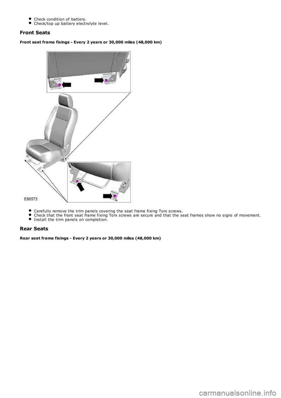
Front Seats
Front seat frame fixings - Every 2 years or 30,000 miles (48,000 km)
Careful ly remove t he trim panel s covering t he s eat frame fi xi ng Torx s crews .Check t hat the front s eat frame fixing Torx s crews are secure and that the seat frames s how no s i gns of movement .Ins t all the trim panel s on completi on.
Rear Seats
Rear seat frame fixings - Every 2 years or 30,000 miles (48,000 km)
Page 183 of 3229
Check condit ion of batt ery.
Check/top up bat tery electrolyte level .
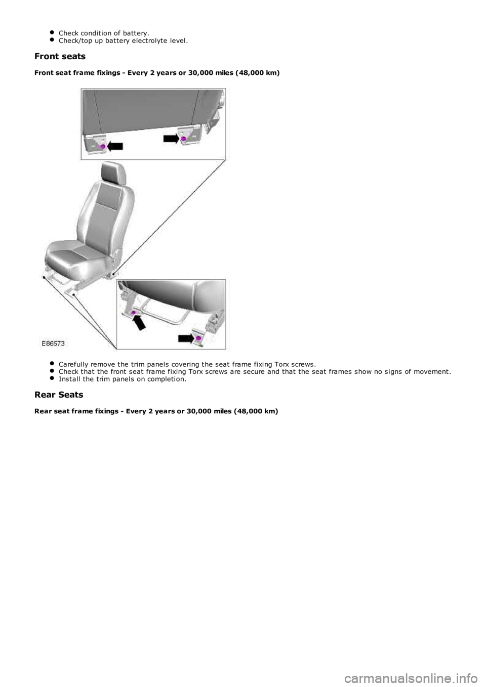
Front seats
Front seat frame fixings - Every 2 years or 30,000 miles (48,000 km) Careful ly remove t he trim panel s covering t he s eat frame fi xi ng Torx s crews .
Check t hat the front s eat frame fixing Torx s crews are secure and that the seat fram
es s how no s i gns of movement .Ins t all the trim panel s on completi on.
Rear Seats
Rear seat frame fixings - Every 2 years or 30,000 miles (48,000 km)
Page 2185 of 3229
6
-St art control modul e
PRINCIPLES OF OPERATION
Front Power Operated Non-Memory Seats
The dri ver's non-memory s eat wil l operate i n all i gni ti on power modes . The pas senger non-memory seat wi ll only operat e
when t he ignit ion i s i n power mode 6 (Ignit ion).
Power for front pas s enger s eat operat ion is s upplied from t he AJB via a pas s enger s e at power relay t o t he pas s enger s eat
cont rol s wit ch pack. Power for t he driver's s eat operat ion is s upplied di rectl y from the AJB t o t he dri ver's s eat cont rol
s wit ch pack. The front pas s enger and dri ver s eat power suppli es are controlled by th e CJB. The s eat s wi tch pack direct s the
volt age to t he relevant s eat adjus tment mot or when a s eat control swit ch is pres s ed. Two pins wi thin each of t he s eat
s wit ch packs cont rol t he s eat motors. Bot h pins are normal ly connect ed to ground.
The dri ver and pas senger s wit ch packs are al s o connected i n circui t wit h a bat tery-s aver t imer relay t hat i s located in, and
cont rol led by t he CJB. The bat tery-s aver t imer relay all ows operati on of the driver and pas s enger s eat cont rols for 10
mi nut es aft er the engine is s wit ched off, and the i gni ti on is then s elected t o an ap propriat e power mode. The 10 minute
t imer is res et if t he appropriat e i gni ti on power mode is retai ned and the driver's d oor i s opened or clos ed. The driver and
pass enger s eat operati on is inhibit ed i mmediat el y fol lowi ng cent ral locking of t he v ehi cl e.
Operat ing a seat mot or control swit ch appli es volt age to one of t he pins whi le t he o t her pi n remai ns connect ed t o ground.
Operat ing t he s eat motor cont rol s wit ch in the oppos it e direct ion reverses the power and ground connecti ons to the mot or,
all owing t he mot or pi ni on t o rot ate in t he oppos i te di recti on. In t he event t hat a m ot or sei zes or s t icks , an i nternal
t hermal cut -out s wit ch wil l trip to remove volt age from t he mot or.
Driver's Power Operated Memory Seat
The dri ver's memory s eat wil l operat e when t he i gni ti on is in power modes 4 (Acces so ry) and 6 (Ignit ion), and wi ll not
operate during power mode 9 (Engine crank).
Power for the driver's memory s eat operat ion i s s uppl ied di rectl y from t he AJB t o t h e power s eat module. The memory s eat
s wit ch pack i s connected t o t he power seat module that cont rol s t he operati on and me mory pos it ion of t he i ndi vi dual s eat
mot ors . The power s eat module i s connected on the medi um s peed CAN bus t o t he CJB an d the front LH and RH door
cont rol modules .
The power seat module is als o connect ed in ci rcuit wi th a batt ery-saver ti mer rel ay that is locat ed wi thin, and controlled by
t he CJB. The batt ery-saver ti mer rel ay allows operat ion of t he s eat cont rols for 10 mi nut es aft er the engine is s wi tched off,
and t he ignit ion i s t hen sel ect ed to an appropri at e power mode. The 10 minut e t imer i s res et if t he appropri at e i gni ti on
power mode is retai ned and the driver's door i s opened or clos ed. The driver's s eat operat ion is i nhi bit ed immedi ately
fol lowing cent ral locki ng of the vehicl e.
Reques t s for memory exterior mirror movements for a memory recal l are t rans mit ted on the medi um s peed CAN bus by t he
power seat module to t he front door control modul es. The front door cont rol modules direct ly control the memory s t ore and
recall pos it ions for t he memory ext eri or mirrors.
For addit ional informat ion, refer t o: Rear Vi ew Mi rrors (501-09 Rear View Mirrors , Des cript ion and Operat ion).
Power Seat Mod ule
The power seat module features driver s electable funct ions , and aut omat ic monit ori ng functi ons .
Driver Selectable Functions
Seat and ext erior mirror memory recall Immediat e s eat adjus t ment.
Seat and exterior mirror memory recall function
The memory recall functi on s ets t he driver's seat t o a s t ored pos it ion, and is acti v at ed when a swi tch pack memory
posi ti on butt on is pres sed. W hen memory recal l i s i ni ti ated, only 2 seat adjus tment mot ors wil l operat e at any one t ime to
li mit the overall current cons umpti on. To furt her minimize t he current l oad as the m otors energize, the i nit iati on of each of
t he 2 operati ng mot ors i s phas ed wi th a 10 mill is econd del ay. The cushi on s lide and backres t wil l move fi rs t , foll owed by
t he cus hion height .
As s oon as t he seat s wit ch pack memory pos it ion but ton is pres s ed, a mes sage i s t ran s mit ted by the power s eat modul e
on t he medium s peed CAN bus to the front door control modul es. The door cont rol modu les t hen act ivat e t he memory
recall pos it ions for t he exteri or mirrors. The i nst rument clus t er mess age cent er wil l di s pl ay memory recall mes s ages when
a memory recall i s acti vat ed.
The memory recall functi on operates wit h 2 s eparate modes; t he operat ion of each mod e is dependant on t he vehicle
s tat us when the seat memory posi ti on butt on is pres sed.
Memory recall operati ng modes:
One-t ouch mode Proport ional mode.
One-Touch Mode
W hen t he vehicle i s s tat ionary and a s wit ch pack memory pos it ion butt on i s pres sed, t he memory recall functi on wil l
operate in 'one-touch' mode. One t ouch mode all ows the seat and exterior mirrors t o immediatel y move t o t he request ed
s tored memory pos i ti on.
If a s eat adjus t ment or memory pos it ion but ton i s operat ed during memory recal l 'one -t ouch' mode, t he current memory
recall wi ll be cancell ed and t he seat (and ext eri or mirrors via t he medium s peed CAN bus) wi ll i mmediat el y s top movi ng.
The s eat will t hen commence movi ng in the di recti on that corresponds to the press ed s wi tch.
Page 2580 of 3229
Publ is hed: 11-May-2011
Roof Sheet Metal Repairs - Roof PanelVehicles Without: Sliding Roof
Opening Panel
Removal and Installation
Removal
• NOTE: The roof is serviced as a separate weld on panel, less its reinforcements.
• NOTE: Along the RH and LH sides of the panel, spot welds should be installed adjacent to the originals and not in the
same locations.
1. The roof panel is replaced in conjunction with:
Liftgate
Windshield
2. Fo r a d d i t i o na l i nf o rma t i o n re l a t i ng t o t hi s re p a i r p ro ce d ure
please see the following:
Fo r a d d i t i o na l i nf o rma t i o n, re f e r t o : Body and Frame
(501-26
Body Repairs - Vehicle Specific Information and Tolerance
Checks, Description and Operation) /
St a nd a rd W o rks ho p P ra ct i ce s
(100-00 Ge ne ra l I nf o rma t i o n,
Description and Operation).
3. Disconnect both battery cables.
4. Remove the liftgate.
Fo r a d d i t i o na l i nf o rma t i o n, re f e r t o : Liftgate
(501-03 Body
Closures, Removal and Installation).
5. Remove the windshield glass.
Fo r a d d i t i o na l i nf o rma t i o n, re f e r t o : Windshield Glass
(501-11
Glass, Frames and Mechanisms, Removal and Installation).
6. Remove both front seats.
Fo r a d d i t i o na l i nf o rma t i o n, re f e r t o : Front Seat
(501-10
Seating, Removal and Installation).
7. Remove the rear seat.
8. Remove bot h side air curt ain modules.
Fo r a d d i t i o na l i nf o rma t i o n, re f e r t o : Side Air Bag Module
(501-20B Suppl ement al Res t rai nt Sys t em, Removal and
Installation).
9. Remove both front safety belt retractors.
Fo r a d d i t i o na l i nf o rma t i o n, re f e r t o : Front Safety Belt Retractor
(501-20A Safe t y Bel t Sys t em, Removal and Ins t al l at i on).
10. Remove both rear safety belt retractors.
Fo r a d d i t i o na l i nf o rma t i o n, re f e r t o : Rear Safety Belt Retractor
(501-20A Safe t y Bel t Sys t em, Removal and Ins t al l at i on).
11. Release and lay aside the wiring harness.
Page 2584 of 3229
Publ is hed: 11-May-2011
Roof Sheet Metal Repairs - Roof Front PanelVehicles With: Sliding Roof
Opening Panel
Removal and Installation
Removal
• NOTE: The roof front panel is serviced as a separate weld-on panel.
1. The roof front panel is replaced in conjunction with:
Windshield
Roof opening panel
2. Fo r a d d i t i o na l i nf o rma t i o n re l a t i ng t o t hi s re p a i r p ro ce d ure
please see the following:
Fo r a d d i t i o na l i nf o rma t i o n, re f e r t o : Body and Frame
(501-26
Body Repairs - Vehicle Specific Information and Tolerance
Checks, Description and Operation) /
St a nd a rd W o rks ho p P ra ct i ce s
(100-00 Ge ne ra l I nf o rma t i o n,
Description and Operation).
3. Disconnect both battery cables.
4. Remove the windshield glass.
Fo r a d d i t i o na l i nf o rma t i o n, re f e r t o : Windshield Glass
(501-11
Glass, Frames and Mechanisms, Removal and Installation).
5. Remove both front seats.
Fo r a d d i t i o na l i nf o rma t i o n, re f e r t o : Front Seat
(501-10
Seating, Removal and Installation).
6. Remove the roof opening panel.
Fo r a d d i t i o na l i nf o rma t i o n, re f e r t o : Roof Opening Panel
(501-17 Roof O peni ng Panel , Removal and Ins t al l at i on).
7. Remove bot h side air curt ain modules.
Fo r a d d i t i o na l i nf o rma t i o n, re f e r t o : Si d e A i r Curt a i n Mo d ul e
(501-20B Suppl ement al Res t rai nt Sys t em, Removal and
Installation).
8. Remove both front safety belt retractors.
Fo r a d d i t i o na l i nf o rma t i o n, re f e r t o : Front Safety Belt Retractor
(501-20A Safe t y Bel t Sys t em, Removal and Ins t al l at i on).
9. Remove both rear safety belt retractors.
Fo r a d d i t i o na l i nf o rma t i o n, re f e r t o : Rear Safety Belt Retractor
(501-20A Safe t y Bel t Sys t em, Removal and Ins t al l at i on).
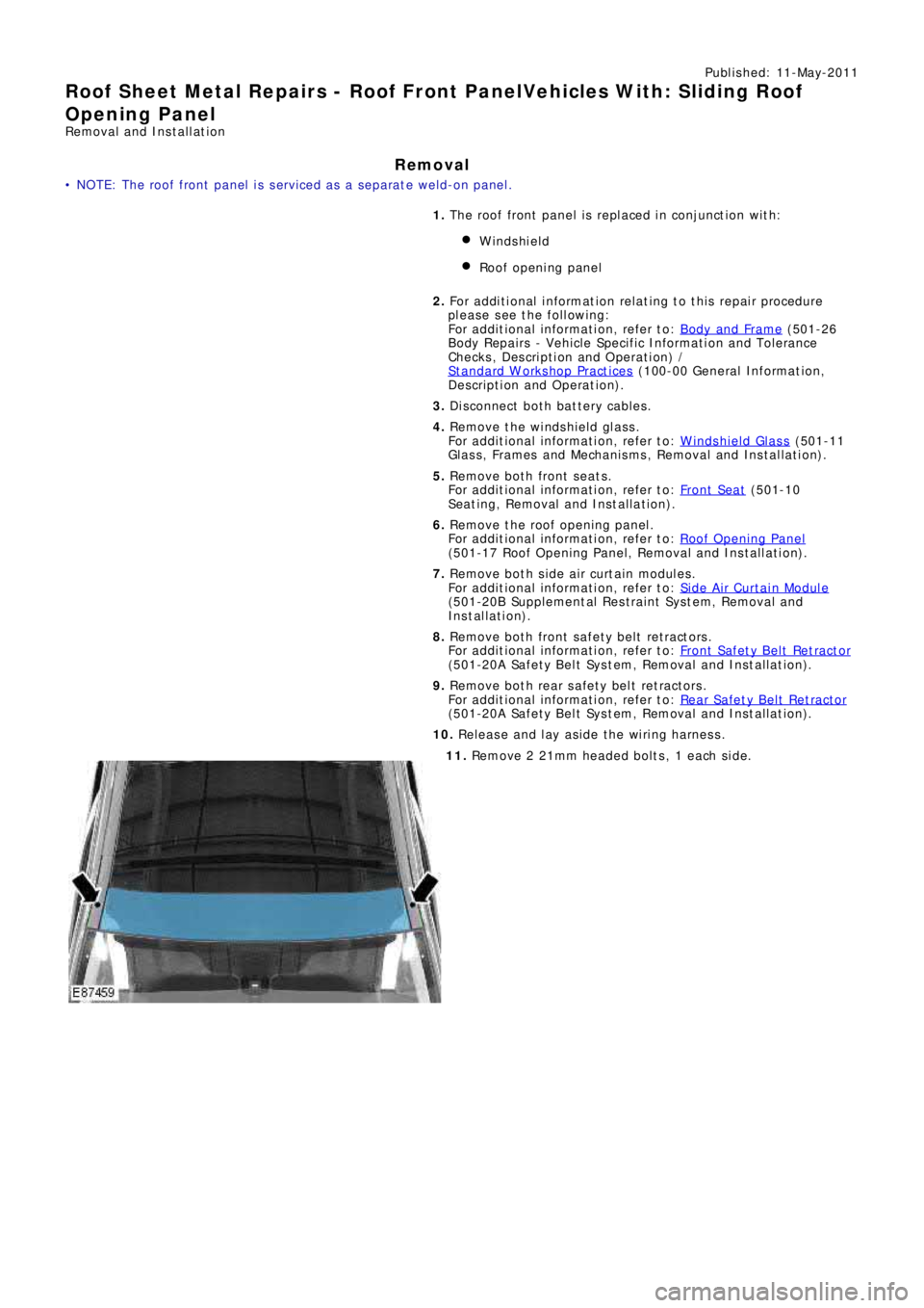
10. Release and lay aside the wiring harness.
11. Re mo ve 2 21mm he a de d bo l t s , 1 e a ch s i de .
Page 2587 of 3229
Publ is hed: 11-May-2011
Roof Sheet Metal Repairs - Roof Rear PanelVehicles With: Sliding Roof
Opening Panel
Removal and Installation
Removal
• NOTE: The roof rear panel is serviced as a separate weld-on panel, less its reinforcements.
• NOTE: Along the RH and LH sides of the panel, spot welds should be installed adjacent to the originals and not in the
same locations.
1. T he ro o f re a r p a ne l i s re p l a ce d i n co nj unct i o n w i t h:
Liftgate
Roof opening panel
2. Fo r a d d i t i o na l i nf o rma t i o n re l a t i ng t o t hi s re p a i r p ro ce d ure
please see the following:
Fo r a d d i t i o na l i nf o rma t i o n, re f e r t o : Body and Frame
(501-26
Body Repairs - Vehicle Specific Information and Tolerance
Checks, Description and Operation) /
St a nd a rd W o rks ho p P ra ct i ce s
(100-00 Ge ne ra l I nf o rma t i o n,
Description and Operation).
3. Disconnect both battery cables.
4. Remove the liftgate.
Fo r a d d i t i o na l i nf o rma t i o n, re f e r t o : Liftgate
(501-03 Body
Closures, Removal and Installation).
5. Remove both front seats.
Fo r a d d i t i o na l i nf o rma t i o n, re f e r t o : Front Seat
(501-10
Seating, Removal and Installation).
6. Remove the rear seat.
7. Remove the roof opening panel.
Fo r a d d i t i o na l i nf o rma t i o n, re f e r t o : Roof Opening Panel
(501-17 Roof O peni ng Panel , Removal and Ins t al l at i on).
8. Remove bot h side air curt ain modules.
Fo r a d d i t i o na l i nf o rma t i o n, re f e r t o : Side Air Bag Module
(501-20B Suppl ement al Res t rai nt Sys t em, Removal and
Installation).
9. Remove both front safety belt retractors.
Fo r a d d i t i o na l i nf o rma t i o n, re f e r t o : Front Safety Belt Retractor
(501-20A Safe t y Bel t Sys t em, Removal and Ins t al l at i on).
10. Remove both rear safety belt retractors.
Fo r a d d i t i o na l i nf o rma t i o n, re f e r t o : Rear Safety Belt Retractor
(501-20A Safe t y Bel t Sys t em, Removal and Ins t al l at i on).
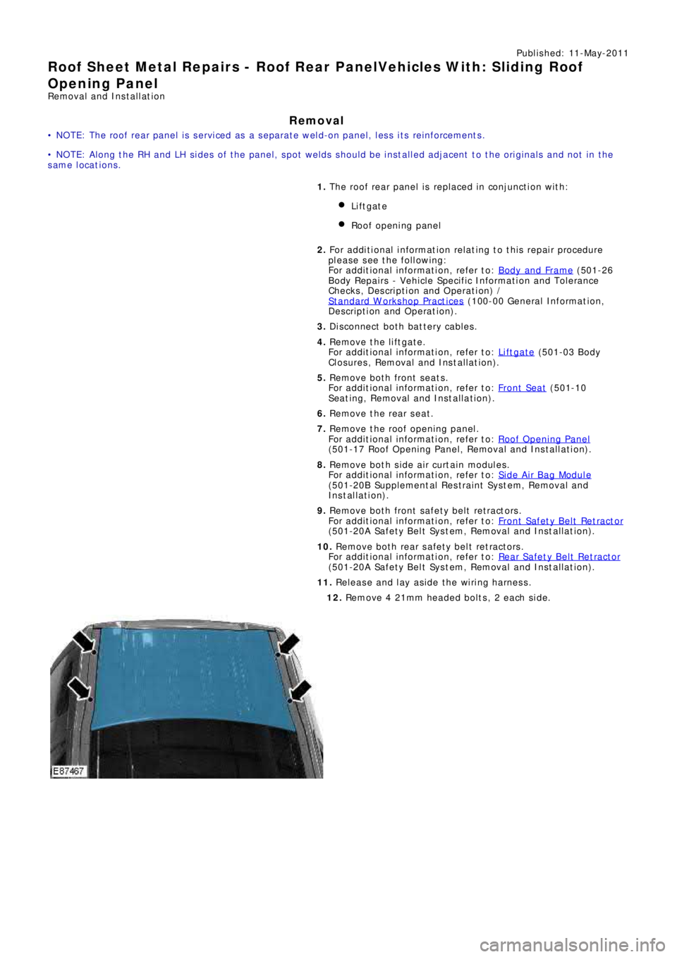
11. Release and lay aside the wiring harness.
12. Re mo ve 4 21mm he a de d bo l t s , 2 e a ch s i de .
Page 2730 of 3229
10
Quick start
L
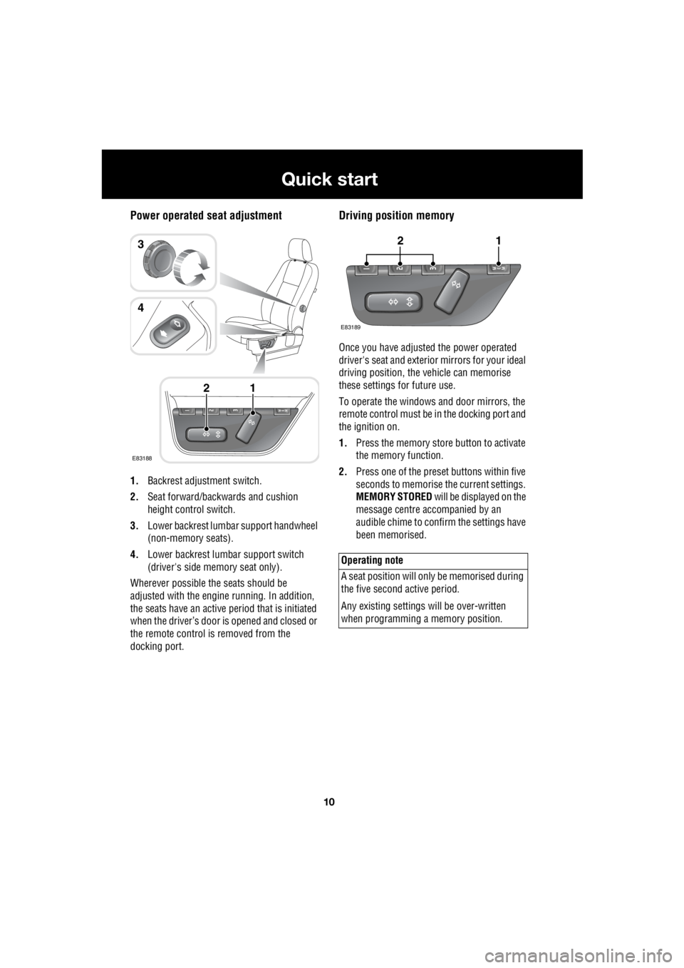
Power operated seat adjustment
1. Backrest adjustment switch.
2. Seat forward/backwards and cushion
height control switch.
3. Lower backrest lumbar support handwheel
(non-memory seats).
4. Lower backrest lumbar support switch
(driver's side memory seat only).
Wherever possible the seats should be
adjusted with the engine running. In addition,
the seats have an active period that is initiated
when the driver’s door is opened and closed or
the remote control is removed from the
docking port.
Driving position memory
Once you have adjusted the power operated
driver's seat and exterior mirrors for your ideal
driving position, the vehicle can memorise
these settings for future use.
To operate the windows and door mirrors, the
remote control must be in the docking port and
the ignition on.
1. Press the memory store button to activate
the memory function.
2. Press one of the preset buttons within five
seconds to memorise the current settings.
MEMORY STORED will be displayed on the
message centre accompanied by an
audible chime to confirm the settings have
been memorised.
E83188
12
3
4
Operating note
A seat position will onl y be memorised during
the five second active period.
Any existing settings w ill be over-written
when programming a memory position.
E83189
12
Page 2770 of 3229
Seats
50
L
To adjust the seats, the remote control must be
inserted in the starter control unit and the
ignition on. On those ve hicles equipped with
the memory driver's seat, the seat has a 10
minute active peri od, initiated when the driver's
door is opened/closed or the remote control is
removed from the starter control unit.
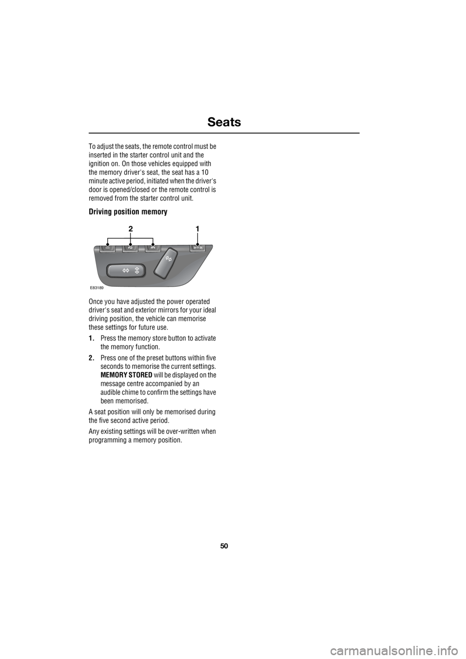
Driving position memory
Once you have adjusted the power operated
driver's seat and exterior mirrors for your ideal
driving position, the vehicle can memorise
these settings for future use.
1. Press the memory stor e button to activate
the memory function.
2. Press one of the preset buttons within five
seconds to memorise the current settings.
MEMORY STORED will be displayed on the
message centre accompanied by an
audible chime to conf irm the settings have
been memorised.
A seat position will only be memorised during
the five second active period.
Any existing settings will be over-written when
programming a memory position.
E83189
12