Page 317 of 3229

Publ is hed: 23-Sep-2011
Rear Drive Axle/Differential -
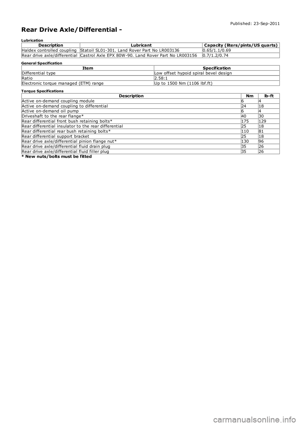
LubricationDescriptionLubricantCapacity (liters/pints/US quarts)
Haldex controlled coupli ngSt at oil SL01-301. Land Rover Part No LR0031360.65/1.1/0.69
Rear drive axl e/different ialCas trol Axl e EPX 80W -90. Land Rover Part No LR0031560.7/1.2/0.74
General Specification
ItemSpecificationDi fferenti al t ypeLow offset hypoi d s piral bevel des ign
Rati o2.58:1
Electronic t orque managed (ETM) rangeUp to 1500 Nm (1106 lbf.ft)
Torque SpecificationsDescriptionNmlb-ft
Acti ve on-demand coupl ing module64
Acti ve on-demand coupl ing t o different ial2418Acti ve on-demand oil pump64
Driveshaft to the rear flange*4030
Rear different ial front bus h retaini ng bol ts *175129Rear different ial ins ulator t o t he rear different ial2518
Rear different ial rear bush ret ai ning bolt s *11081
Rear different ial support bracket2518Rear drive axl e/different ial pinion fl ange nut *13096
Rear drive axl e/different ial fl uid drain pl ug3526
Rear drive axl e/different ial fl uid fil ler plug3526* New nuts/bolts must be fitted
Page 604 of 3229

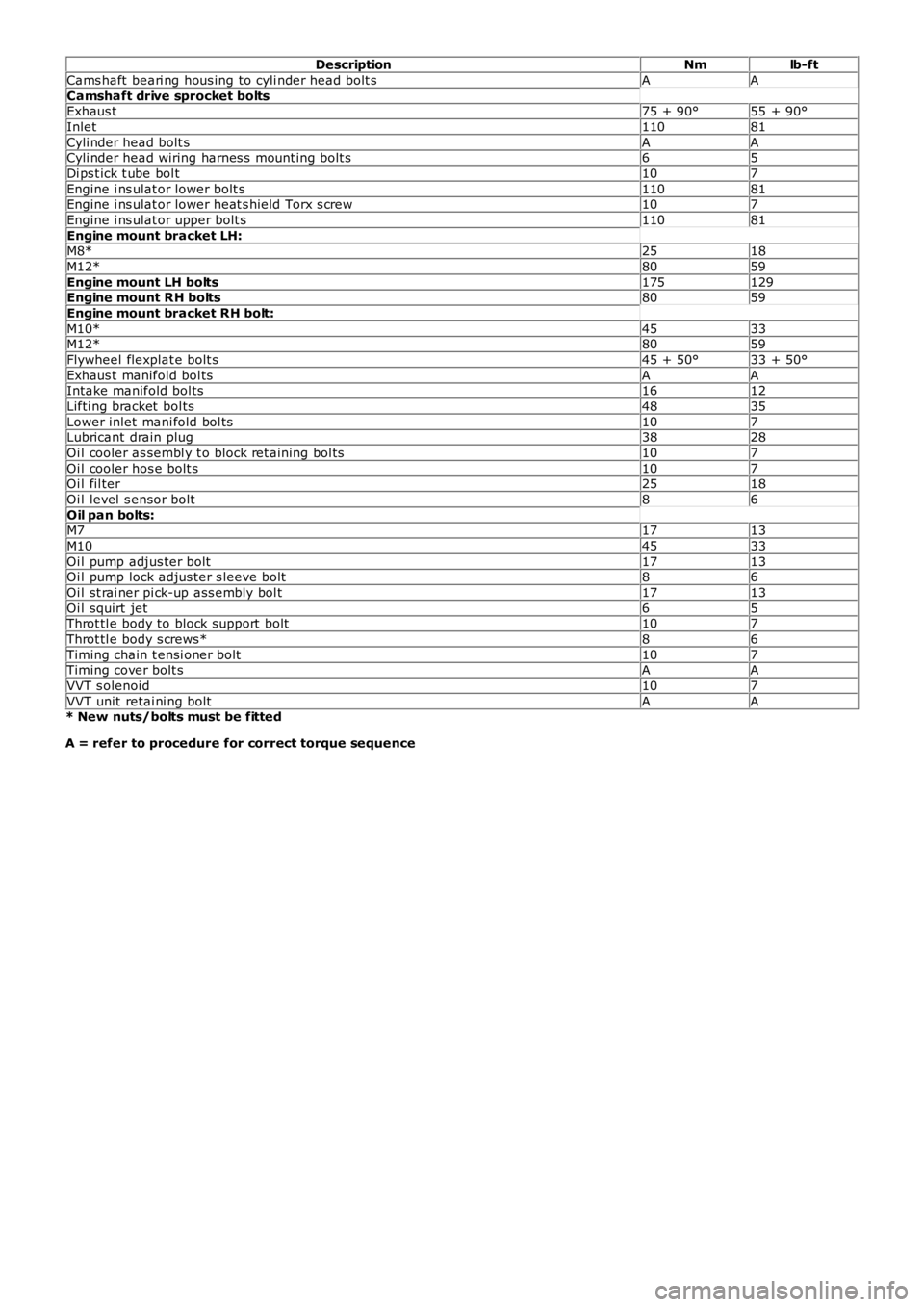
DescriptionNmlb-ft
Cams haft beari ng hous ing to cyli nder head bolt sAA
Camshaft drive sprocket boltsExhaus t75 + 90°55 + 90°
Inlet11081
Cyli nder head bolt sAACyli nder head wiring harnes s mount ing bolt s65
Di ps t ick t ube bol t107
Engine i ns ulat or lower bolt s11081Engine i ns ulat or lower heat s hield Torx s crew107
Engine i ns ulat or upper bolt s11081
Engine mount bracket LH:M8*2518
M12*8059
Engine mount LH bolts175129Engine mount RH bolts8059
Engine mount bracket RH bolt:
M10*4533M12*8059
Flywheel flexplat e bolt s45 + 50°33 + 50°
Exhaus t manifold bol tsAAIntake manifold bol ts1612
Lifti ng bracket bol ts4835
Lower inlet mani fold bol ts107Lubricant drain plug3828
Oi l cooler as sembl y t o block ret aining bol ts107
Oi l cooler hos e bolt s107Oi l fil ter2518
Oi l level s ensor bolt86
Oil pan bolts:M71713
M104533
Oi l pump adjus ter bolt1713Oi l pump lock adjus ter s leeve bolt86
Oi l st rai ner pi ck-up ass embly bol t1713
Oi l squirt jet65Throt tl e body to block support bolt107
Throt tl e body s crews*86
Timing chain t ensi oner bolt107Timing cover bolt sAA
VVT s olenoid107
VVT unit retai ni ng boltAA* New nuts/bolts must be fitted
A = refer to procedure for correct torque sequence
Page 616 of 3229

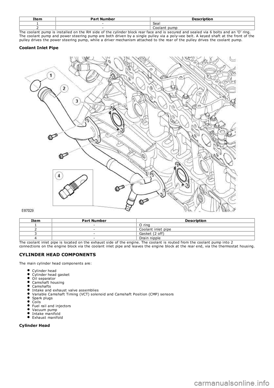
ItemPart NumberDescription1-Seal2-Coolant pumpThe coolant pump is ins t alled on t he RH side of t he cylinder block rear face and is s ecured and s ealed via 6 bolt s and an 'O' ring.The coolant pump and power s t eering pump are bot h driven by a single pulley via a poly-vee belt . A keyed s haft at the front of t hepulley drives t he power s teering pump, while a driver mechanism at t ached to t he rear of t he pulley drives the coolant pump.
Coolant Inlet Pipe
ItemPart NumberDescription1-O ring2-Coolant inlet pipe3-Gas ket (2 off)4-Drain nippleThe coolant inlet pipe is locat ed on t he exhaus t s ide of the engine. The coolant is rout ed from t he coolant pump int o 2connect ions on the engine block via t he coolant inlet pipe and leaves t he engine block at t he rear end, via t he t hermos tat hous ing.
CYLINDER HEAD COMPONENTS
The main cylinder head component s are:
Cylinder headCylinder head gas ketO il s eparat orCams haft hous ingCams haftsIntake and exhaust valve ass embliesVariable Cams haft Timing (VCT) s olenoid and Cams haft Posit ion (CMP) sens orsSpark plugsCoilsFuel rail and injectorsVacuum pumpIntake manifoldExhaus t manifold
Cylinder Head
Page 635 of 3229
The bedplat e is of an aluminium alloy s t ruct ure bolt ed t o t he bot t om of the cylinder block t o furt her improve rigidit y and t o retainthe crankshaft . The 7 cas t iron cranks haft bearing caps are cas t in t he boreholes .
A windage t ray at t ached to the underside of t he bedplat e isolates t he oil pan from the dis t urbed air produced by t he rotat ion ofthe crankshaft , to prevent oil aeration and improve oil drainage.
Oil Filter and Cooler Assembly
Page 638 of 3229
Oil Pan
ItemPart NumberDescription1-Oil pan2-Oil drain plugThe aluminium alloy s truct ural oil pan is bolted t o t he bedplat e.
• NOTE: The oil pan s hould always be fit ted proud of t he bedplat e by 0.05mm (+0mm -0.05mm).
A combined oil level/t emperat ure sensor is at t ached to t he underside of t he oil pan via 3 bolt s. The tip of the s ens or locat esthrough an aperture and is s ealed wit h an O-ring.
Page 753 of 3229
DescriptionNmlb-ft
Engine mount bracket LH:
M8*2518M12*8059
Engine mount bracket RH:
M12*8059M14*175129
Engine mount LH bolt175129
Engine mount RH bol ts8059Flywheel bol tsAA
Fuel i njector wi ri ng harness bol t107
Fuel fil ter bracket bol ts2518Intake manifold runner control (IMRC) act uat or bol t107
Intake manifold adaptor and t hrot tl e hous i ng bol t65
Intake manifold bol ts97Lifti ng bracket s107
Oi l cooler brackets107
Oi l cooler t o cyl inder block bol ts2015Oi l fil ler t ube97
Oi l pan drain pl ug2015
Oi l pan bol ts97Oil pan extension panel:
St age 1107
St age 21612Oil pump bolts:97
St age 175
St age 297Oi l separat or bol ts75
Oi l level s ensor86
Pis t on cool ing jet bol t107Timing belt t ensi oner bolt2518
Timing belt i dler pulley bol t6044
Timing belt rear cover64Valve cover bol ts107
Vacuum pump bolt s97
* New nuts/bolts must be fitted
A = refer to procedure for correct torque sequence
Page 776 of 3229

ItemPart NumberDescription
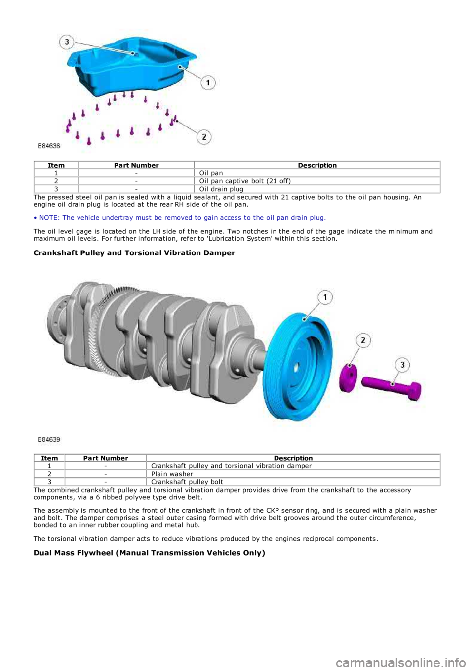
1-Oil pan2-Oil pan capti ve bol t (21 off)
3-Oil drai n plug
The pres s ed s teel oil pan is sealed wit h a l iquid sealant , and secured wi th 21 capt ive bolt s t o t he oil pan housi ng. Anengi ne oil drai n plug is l ocat ed at the rear RH s ide of t he oil pan.
• NOTE: The vehi cle undert ray mus t be removed to gai n acces s t o t he oil pan drain plug.
The oil l evel gage is l ocat ed on t he LH s ide of t he engi ne. Two not ches in t he end of t he gage indicate t he mi nimum andmaximum oil l evels . For further informat ion, refer t o 'Lubricat ion Sys t em' wit hi n t his s ect ion.
Crankshaft Pulley and Torsional Vibration Damper
ItemPart NumberDescription
1-Cranks haft pull ey and torsi onal vibrat ion damper
2-Plai n was her3-Cranks haft pull ey bol t
The combined crankshaft pul ley and t ors ional vi brat ion damper provides dri ve from t he crankshaft to the acces s orycomponents , via a 6 ribbed polyvee type drive belt .
The as sembl y is mount ed t o t he front of t he crankshaft in front of t he CKP s ens or ring, and i s s ecured wit h a pl ain was herand bolt . The damper compri ses a s teel out er cas i ng formed wit h drive belt grooves around t he outer circumference,bonded t o an inner rubber coupl ing and metal hub.
The t ors ional vi brati on damper act s to reduce vibrat ions produced by the engines reci procal component s .
Dual Mass Flywheel (Manual Transmission Vehicles Only)
Page 882 of 3229
Di sconnect t he oil level sens or elect rical s ens or.5.
Releas e t he crankcas e vent oi l separat or drain tube.6.
Remove t he 4 t rans mis s ion bolt s .7.