2006 LAND ROVER FRELANDER 2 USB
[x] Cancel search: USBPage 78 of 3229
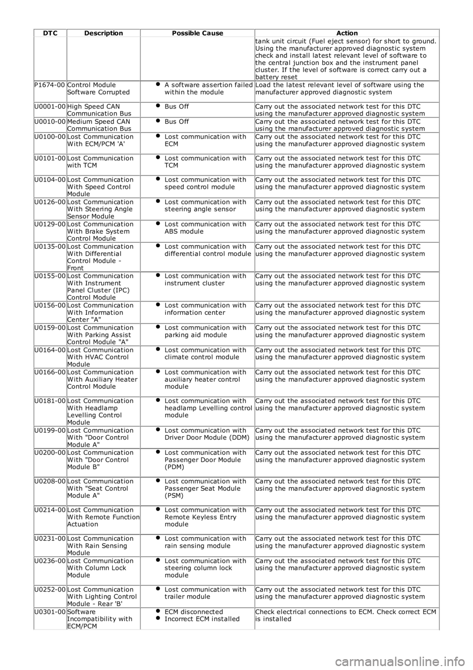
DT CDescriptionPossible CauseAction
tank unit ci rcuit (Fuel eject s ens or) for s hort to ground.Us ing t he manufacturer approved diagnost ic sys temcheck and ins t al l lat es t relevant l evel of s oft ware t othe central juncti on box and the i nst rument panelcl ust er. If t he level of s oft ware is correct carry out abat t ery resetP1674-00Control ModuleSoft ware Corrupt edA s oft ware as s ert ion fai ledwit hi n t he moduleLoad the l ates t rel evant level of s oftware usi ng t hemanufacturer approved diagnost ic sys tem
U0001-00High Speed CANCommunicati on BusBus O ffCarry out the as s oci at ed network t es t for this DTCusi ng t he manufact urer approved diagnost ic s ys tem
U0010-00Medium Speed CANCommunicati on BusBus O ffCarry out the as s oci at ed network t es t for this DTCusi ng t he manufact urer approved diagnost ic s ys tem
U0100-00Lost Communi cat ionW i th ECM/PCM 'A'Los t communicat ion wit hECMCarry out the as s oci at ed network t es t for this DTCusi ng t he manufact urer approved diagnost ic s ys tem
U0101-00Lost Communi cat ionwi th TCMLos t communicat ion wit hTCMCarry out the as s oci at ed network t es t for this DTCusi ng t he manufact urer approved diagnost ic s ys tem
U0104-00Lost Communi cat ionW i th Speed Cont rolModule
Los t communicat ion wit hs peed cont rol moduleCarry out the as s oci at ed network t es t for this DTCusi ng t he manufact urer approved diagnost ic s ys tem
U0126-00Lost Communi cat ionW i th Steeri ng AngleSensor Module
Los t communicat ion wit hs t eering angle s ens orCarry out the as s oci at ed network t es t for this DTCusi ng t he manufact urer approved diagnost ic s ys tem
U0129-00Lost Communi cat ionW i th Brake Syst emControl Module
Los t communicat ion wit hABS modul eCarry out the as s oci at ed network t es t for this DTCusi ng t he manufact urer approved diagnost ic s ys tem
U0135-00Lost Communi cat ionW i th Different ialControl Module -Front
Los t communicat ion wit hdi fferenti al control modul eCarry out the as s oci at ed network t es t for this DTCusi ng t he manufact urer approved diagnost ic s ys tem
U0155-00Lost Communi cat ionW i th Ins t rumentPanel Cl us t er (IPC)Control Module
Los t communicat ion wit hi nst rument clus t erCarry out the as s oci at ed network t es t for this DTCusi ng t he manufact urer approved diagnost ic s ys tem
U0156-00Lost Communi cat ionW i th Informat ionCenter "A"
Los t communicat ion wit hi nformati on cent erCarry out the as s oci at ed network t es t for this DTCusi ng t he manufact urer approved diagnost ic s ys tem
U0159-00Lost Communi cat ionW i th Parking As s is tControl Module "A"
Los t communicat ion wit hparki ng aid modul eCarry out the as s oci at ed network t es t for this DTCusi ng t he manufact urer approved diagnost ic s ys tem
U0164-00Lost Communi cat ionW i th HVAC ControlModule
Los t communicat ion wit hcl imat e cont rol moduleCarry out the as s oci at ed network t es t for this DTCusi ng t he manufact urer approved diagnost ic s ys tem
U0166-00Lost Communi cat ionW i th Auxi li ary HeaterControl Module
Los t communicat ion wit hauxil iary heat er cont rolmodul e
Carry out the as s oci at ed network t es t for this DTCusi ng t he manufact urer approved diagnost ic s ys tem
U0181-00Lost Communi cat ionW i th Headl ampLevel ling Cont rolModule
Los t communicat ion wit hheadlamp Levell ing controlmodul e
Carry out the as s oci at ed network t es t for this DTCusi ng t he manufact urer approved diagnost ic s ys tem
U0199-00Lost Communi cat ionW i th "Door ControlModule A"
Los t communicat ion wit hDriver Door Modul e (DDM)Carry out the as s oci at ed network t es t for this DTCusi ng t he manufact urer approved diagnost ic s ys tem
U0200-00Lost Communi cat ionW i th "Door ControlModule B"
Los t communicat ion wit hPas s enger Door Modul e(PDM)
Carry out the as s oci at ed network t es t for this DTCusi ng t he manufact urer approved diagnost ic s ys tem
U0208-00Lost Communi cat ionW i th "Seat ControlModule A"
Los t communicat ion wit hPas s enger Seat Modul e(PSM)
Carry out the as s oci at ed network t es t for this DTCusi ng t he manufact urer approved diagnost ic s ys tem
U0214-00Lost Communi cat ionW i th Remote Functi onActuati on
Los t communicat ion wit hRemot e Keyles s Entrymodul e
Carry out the as s oci at ed network t es t for this DTCusi ng t he manufact urer approved diagnost ic s ys tem
U0231-00Lost Communi cat ionW i th Rain Sens ingModule
Los t communicat ion wit hrain sens ing moduleCarry out the as s oci at ed network t es t for this DTCusi ng t he manufact urer approved diagnost ic s ys tem
U0236-00Lost Communi cat ionW i th Column LockModule
Los t communicat ion wit hs t eering column lockmodul e
Carry out the as s oci at ed network t es t for this DTCusi ng t he manufact urer approved diagnost ic s ys tem
U0252-00Lost Communi cat ionW i th Lighti ng Cont rolModule - Rear 'B'
Los t communicat ion wit ht rai ler moduleCarry out the as s oci at ed network t es t for this DTCusi ng t he manufact urer approved diagnost ic s ys tem
U0301-00Soft wareIncompati bil it y wit hECM/PCM
ECM dis connect edIncorrect ECM i nst all edCheck el ect ri cal connecti ons to ECM. Check correct ECMis i nst all ed
Page 109 of 3229
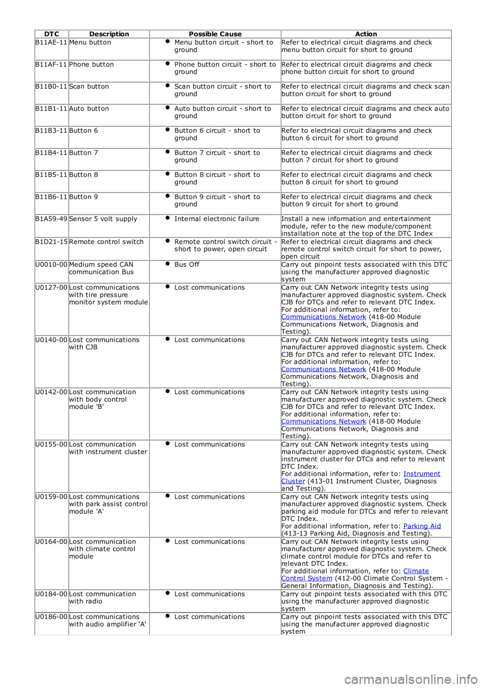
DT CDescriptionPossible CauseAction
B11AE-11Menu butt onMenu but ton ci rcuit - s hort t ogroundRefer to electrical ci rcuit diagrams and checkmenu butt on circui t for s hort t o ground
B11AF-11Phone but t onPhone butt on circui t - s hort togroundRefer to electrical ci rcuit diagrams and checkphone but ton ci rcuit for s hort t o ground
B11B0-11Scan but t onScan butt on circui t - s hort togroundRefer to electrical ci rcuit diagrams and check s canbut t on ci rcuit for short to ground
B11B1-11Auto but t onAut o butt on circui t - s hort togroundRefer to electrical ci rcuit diagrams and check autobut t on ci rcuit for short to ground
B11B3-11Butt on 6But ton 6 circuit - short togroundRefer to electrical ci rcuit diagrams and checkbut t on 6 circui t for s hort t o ground
B11B4-11Butt on 7But ton 7 circuit - short togroundRefer to electrical ci rcuit diagrams and checkbut t on 7 circui t for s hort t o ground
B11B5-11Butt on 8But ton 8 circuit - short togroundRefer to electrical ci rcuit diagrams and checkbut t on 8 circui t for s hort t o ground
B11B6-11Butt on 9But ton 9 circuit - short togroundRefer to electrical ci rcuit diagrams and checkbut t on 9 circui t for s hort t o ground
B1A59-49Sensor 5 volt supplyInternal el ect ronic fail ureIns t al l a new i nformat ion and ent ert ainmentmodule, refer t o t he new modul e/componentins tal lati on note at the t op of the DTC Index
B1D21-15Remote cont rol s wit chRemot e control s wi tch circui t -s hort t o power, open circui tRefer to electrical ci rcuit diagrams and checkremot e cont rol s wi tch circui t for s hort t o power,open ci rcuitU0010-00Medium s peed CANcommunicati on BusBus O ffCarry out pi npoi nt tes ts as s oci ated wit h thi s DTCusi ng t he manufact urer approved diagnost ics ys t em
U0127-00Lost communi cat ionswi th t ire pres s uremonit or s ys t em module
Los t communicat ionsCarry out CAN Network int egrit y t est s us ingmanufacturer approved diagnost ic sys tem. CheckCJB for DTCs and refer to relevant DTC Index.For addit ional informati on, refer t o:Communicati ons Net work (418-00 ModuleCommunicati ons Net work, Di agnos is andTes t ing).
U0140-00Lost communi cat ionswi th CJBLos t communicat ionsCarry out CAN Network int egrit y t est s us ingmanufacturer approved diagnost ic sys tem. CheckCJB for DTCs and refer to relevant DTC Index.For addit ional informati on, refer t o:Communicati ons Net work (418-00 ModuleCommunicati ons Net work, Di agnos is andTes t ing).U0142-00Lost communi cat ionwi th body controlmodule 'B'
Los t communicat ionsCarry out CAN Network int egrit y t est s us ingmanufacturer approved diagnost ic sys tem. CheckCJB for DTCs and refer to relevant DTC Index.For addit ional informati on, refer t o:Communicati ons Net work (418-00 ModuleCommunicati ons Net work, Di agnos is andTes t ing).
U0155-00Lost communi cat ionwi th i nst rument clus t erLos t communicat ionsCarry out CAN Network int egrit y t est s us ingmanufacturer approved diagnost ic sys tem. Checkins trument cl ust er for DTCs and refer to relevantDTC Index.For addit ional informati on, refer t o: Ins trumentClus ter (413-01 Ins t rument Clus t er, Diagnosi sand Tes t ing).
U0159-00Lost communi cat ionswi th park ass i st controlmodule 'A'
Los t communicat ionsCarry out CAN Network int egrit y t est s us ingmanufacturer approved diagnost ic sys tem. Checkparking ai d module for DTCs and refer t o relevantDTC Index.For addit ional informati on, refer t o: Parking Ai d(413-13 Parking Aid, Di agnos is and Tes ti ng).
U0164-00Lost communi cat ionwi th cl imat e cont rolmodule
Los t communicat ionsCarry out CAN Network int egrit y t est s us ingmanufacturer approved diagnost ic sys tem. Checkcl imat e control modul e for DTCs and refer t orel evant DTC Index.For addit ional informati on, refer t o: ClimateCont rol Sys tem (412-00 Cl imat e Control Sys t em -General Informati on, Diagnos is and Tes t ing).
U0184-00Lost communi cat ionwi th radioLos t communicat ionsCarry out pi npoi nt tes ts as s oci ated wit h thi s DTCusi ng t he manufact urer approved diagnost ics ys t emU0186-00Lost communi cat ionswi th audio amplifier 'A'Los t communicat ionsCarry out pi npoi nt tes ts as s oci ated wit h thi s DTCusi ng t he manufact urer approved diagnost ics ys t em
Page 112 of 3229
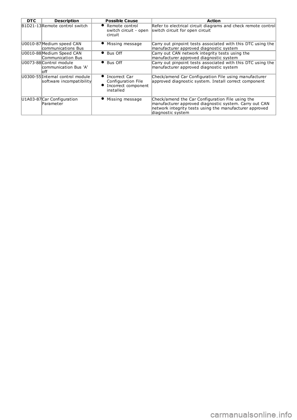
DT CDescriptionPossible CauseAction
B1D21-13Remote cont rol s wit chRemote cont rols wit ch circuit - opencircui t
Refer t o electrical ci rcuit diagrams and check remote controls wit ch ci rcuit for open ci rcuit
U0010-87Medium speed CANcommunicati ons BusMi ss ing mess ageCarry out pi npoi nt tes ts ass ociated wit h t hi s DTC us ing t hemanufacturer approved diagnost ic sys temU0010-88Medium Speed CANCommunicati on BusBus OffCarry out CAN network int egrit y t est s us ing t hemanufacturer approved diagnost ic sys temU0073-88Control modul ecommunicati on Bus 'A'off
Bus OffCarry out pi npoi nt tes ts ass ociated wit h t hi s DTC us ing t hemanufacturer approved diagnost ic sys tem
U0300-55Int ernal cont rol modules oft ware i ncompat ibil it yIncorrect CarConfi gurati on Fi leIncorrect componentins t al led
Check/amend Car Confi gurati on Fil e usi ng manufacturerapproved di agnos t ic s yst em. Ins t all correct component
U1A03-87Car Configurat ionParamet erMi ss ing mess ageCheck/amend the Car Confi gurati on Fi le us i ng themanufacturer approved diagnost ic sys tem. Carry out CANnetwork int egrit y t es t s us ing t he manufacturer approveddiagnos t ic s ys tem
Page 113 of 3229

Publi s hed: 03-May-2011
General Information - Diagnostic Trouble Code (DTC) IndexDTC:
Instrument Cluster (IPC)
Des cript ion and Operat ion
• NOTE: If a cont rol module or component i s s uspect and the vehicl e remai ns under manufacturer warrant y, refer t o t heW arranty Pol icy and Procedures manual (s ect ion B1.2), or determine i f any pri or approval program is i n operat ion, beforet he replacement of a component.
• NOTE: Generic scan t ool s may not read the codes li st ed, or may read only 5-digi t codes . Match t he 5 digi ts from t he s cant ool t o t he fi rs t 5 di gi ts of the 7-digit code li s ted t o i dent ify the fault (the last 2 digi ts gi ve ext ra informati on read by themanufacturer-approved di agnos ti c s ys t em).
• NOTE: W hen performing volt age or res is t ance t est s , always use a digi tal mult imeter (DMM) accurat e t o t hree deci malplaces, and wi th an up-t o-date cal ibrat ion cert ificate. W hen tes ti ng res is t ance al ways take t he res is t ance of t he DMMleads i nt o account .
• NOTE: Check and recti fy bas ic faul ts before beginni ng diagnos t ic rout ines i nvol vi ng pinpoint t es t s.
• NOTE: Ins pect connect ors for s igns of water ingres s , and pins for damage and/or corros ion.
• NOTE: If DTCs are recorded and, aft er performi ng the pi npoi nt tes ts , a fault is not present , an int ermi tt ent concern maybe t he caus e. Always check for loose connect ions and corroded terminals .
Des cript ion And Operat ion
For a detail ed descripti on of the ins trument cl us t er sys tem, refer t o t he rel evant Descripti on and Operat ion s ecti on in t heworks hop manual .For addit ional informat ion, refer t o: Ins t rument Clus ter (413-01 Inst rument Cl us t er, Des cript ion and Operat ion).
Instrument cluster control module (IPC )DT CDescriptionPossible CauseAction
B1184-62Steering Column LockOutputSignal compare fai lureCheck st eering lock power from CJB. Check CJB forDTCs and refer to relevant DTC Index.For addi ti onal informat ion, refer t o:Communicati ons Network (418-00 Modul eCommunicati ons Network, Di agnos is and Tes t ing).
B1A14-96RCM W arning LampLight Emit t ing Di ode (LED)fai lureIns t all a new ins trument cl us t er.For addi ti onal informat ion, refer t o: Ins t rumentClus t er (413-01 Inst rument Cl us t er, Removal andIns t allat ion).Refer t o t he new module/component ins tall ati onnote at the t op of the DTC Index
B1A84-41Car Configurat ion Dat aFlas h download checks umerrorIns t all lat est avail abl e l evel of software us ing t hemanufacturer approved di agnos ti c s ys t em
B1A84-81Car Configurat ion Dat aInvali d Car Configurat iondata recei vedCheck/amend Car Configurat ion Fil e us ingmanufacturer approved di agnos ti c s ys t em
C2002-62Odometer TamperedDTC s et when one or mores tored odomet er val ue doesnot match
Clear DTC, cycle ignit ion and re-t est
U0010-87Medium Speed CANCommunicati on BusMult ipl e los s of CAN dat a toother s yst emsCarry out pinpoint tes t s ass ociat ed wit h t his DTCus ing t he manufacturer approved diagnos ti cs yst em
U0010-88Medium Speed CANCommunicati on BusBreak i n connecti on to busCarry out pinpoint tes t s ass ociat ed wit h t his DTCus ing t he manufacturer approved diagnos ti cs yst emU0140-08Lost Communi cat ionW i th Body Cont rolModule
No mes s ages recei ved fromCJB for great er than t imeoutperi od
Carry out pinpoint tes t s ass ociat ed wit h t his DTCus ing t he manufacturer approved diagnos ti cs yst em
U0208-08Lost Communi cat ionW i th "Seat Cont rolModule A"
No mes s ages recei ved fromDSM for greater t hant imeout period
Check DSM for DTCs and refer t o rel evant DTCIndex.For addi ti onal informat ion, refer t o: Seat s (501-10Seati ng, Di agnos is and Tes ti ng).Carry out CAN Net work i nt egri ty t es ts us ing themanufacturer approved di agnos ti c s ys t emU0300-62Int ernal Cont rol ModuleSoft ware Incompat ibi lit yConfigurat ion dat a receivedis di fferent from the s t oreddata
Check correct ins trument cl us t er is i nst all ed
U3000-46Control ModuleEEPROM writ e errorCheck power and ground circui ts to the i nst rumentclus ter, cl ear DTC and re-tes t. If DTC remains ,ins t al l a new i nst rument clus t er.For addi ti onal informat ion, refer t o: Ins t rumentClus t er (413-01 Inst rument Cl us t er, Removal andIns t allat ion).Refer t o t he new module/component ins tall ati onnote at the t op of the DTC Index
Page 1827 of 3229
Publi s hed: 11-May-2011
Battery, Mounting and Cables -
General SpecificationItemSpecification
Battery - All models:
TypeExide H7Capaci ty80Ah/700CCA
Res erve capacit y125 minutes
Battery Disconnect/C onnect
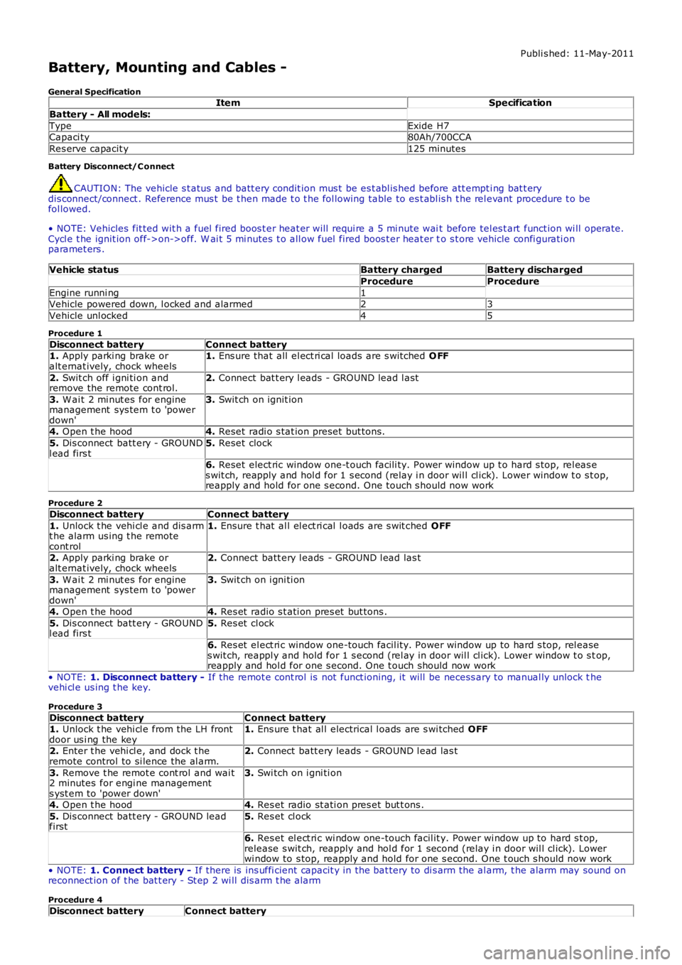
CAUTION: The vehicle s t atus and batt ery condit ion mus t be es t abl is hed before att empti ng bat t erydis connect/connect . Reference mus t be t hen made t o t he fol lowing table to es t abl is h t he rel evant procedure t o befol lowed.
• NOTE: Vehicles fit ted wit h a fuel fired boos t er heat er will requi re a 5 mi nute wait before tel es t art funct ion wi ll operate.Cycl e t he ignit ion off->on->off. W ai t 5 mi nutes t o all ow fuel fired boos t er heat er to s t ore vehicle confi gurati onparamet ers .
Vehicle statusBattery chargedBattery discharged
ProcedureProcedure
Engine runni ng1Vehicle powered down, l ocked and alarmed23
Vehicle unl ocked45
Procedure 1
Disconnect batteryConnect battery1. Apply parki ng brake oralt ernat ively, chock wheels1. Ens ure that all el ect ri cal loads are s wit ched O FF
2. Swit ch off i gni ti on andremove the remote cont rol.2. Connect bat t ery l eads - GROUND lead l ast
3. W ai t 2 mi nut es for enginemanagement sys tem t o 'powerdown'
3. Swit ch on ignit ion
4. Open t he hood4. Reset radi o s tat ion preset but tons .
5. Dis connect batt ery - GROUNDl ead firs t5. Reset clock
6. Reset elect ric window one-t ouch facili ty. Power window up t o hard s top, rel eas es wit ch, reapply and hol d for 1 s econd (relay i n door wil l cl ick). Lower window t o s top,reapply and hold for one s econd. One t ouch s hould now work
Procedure 2
Disconnect batteryConnect battery
1. Unlock t he vehi cl e and dis armt he alarm us ing t he remotecont rol
1. Ensure t hat al l el ect ri cal l oads are s wit ched OFF
2. Apply parki ng brake oralt ernat ively, chock wheels2. Connect batt ery l eads - GROUND l ead las t
3. W ai t 2 mi nut es for enginemanagement sys tem t o 'powerdown'
3. Swit ch on i gni ti on
4. Open t he hood4. Res et radio s t ati on pres et but tons .
5. Dis connect batt ery - GROUNDl ead firs t5. Res et cl ock
6. Res et el ect ri c window one-touch facil it y. Power window up to hard s top, rel eases wit ch, reappl y and hold for 1 s econd (rel ay in door wil l cl ick). Lower window t o s top,reapply and hol d for one s econd. One t ouch should now work
• NOTE: 1. Disconnect battery - If the remot e cont rol is not funct ioning, it will be necess ary to manual ly unlock thevehi cl e us ing t he key.
Procedure 3
Disconnect batteryConnect battery1. Unlock t he vehi cl e from the LH frontdoor us i ng the key1. Ens ure t hat al l electrical l oads are s wi tched OFF
2. Enter t he vehi cl e, and dock t heremote control to si lence the al arm.2. Connect batt ery leads - GROUND l ead las t
3. Remove t he remot e cont rol and wai t2 minutes for engi ne managements yst em to 'power down'
3. Swi tch on i gni ti on
4. Open t he hood4. Res et radio st ati on pres et but t ons .
5. Dis connect batt ery - GROUND leadfirst5. Res et cl ock
6. Res et el ect ri c wi ndow one-touch facil it y. Power wi ndow up to hard s t op,release s wit ch, reapply and hol d for 1 second (relay i n door wil l cl ick). Lowerwi ndow to s top, reapply and hold for one s econd. One t ouch s hould now work
• NOTE: 1. Connect battery - If there is ins uffi cient capacit y in the bat tery to di s arm the al arm, t he alarm may sound onreconnect ion of t he bat t ery - St ep 2 wi ll dis arm t he alarm
Procedure 4
Disconnect batteryConnect battery
Page 1962 of 3229
Publi s hed: 11-May-2011
Module Communications Network - Communications Network
Des cript ion and Operat ion
OVERVIEW
A number of different t ypes of communicati on network are incorporated into the vehicle wiring harnes s es for t het ransmis s ion of commands and informat ion between control modul es. The confi gurati on ins tal led on a parti cul ar vehicl edepends on t he model and equi pment level .
The communicati on net works avail abl e on t he vehi cl e are:
Local Int erconnect Network (LIN) busMedium speed Controll er Area Network (CAN) busHigh speed CAN busMedia O rient ated Sys tem Trans port (MO ST) ring
BusBaud Rate
LIN bus9.6 kbit s /s
Medium s peed CAN bus125 kbi ts /sHi gh Speed CAN bus500 kbi ts /s
MOST ring24 Mbit s/s
LOCAL INTERCONNECT NETWORK BUS
The Local Int erconnect Network (LIN) bus is a low s peed broadcas t net work that employs mas ter and s lave component s .The mas ter component t rans mit s a mess age along a si ngle wi re to the s lave component s i dent ifyi ng which s lave i s t ores pond. The mes s age has a header (s lave ident ifi er) and an empt y data fi eld. The identi fi ed s lave component fi ll s thedata fiel d wi th t he relevant i nformat ion and ret urns a mes s age to the mast er component along t he s ame wire.
CONTROLLER AREA NETWORK BUS
The Control ler Area Network (CAN) bus i s a high speed broadcast net work where cont rol modules aut omat icall y t rans mitinformat ion every few micros econds . Informati on is broadcas t down a pair of t wis t ed wires, known as 'CAN high' and 'CANlow'. Informat ion i s transmit ted on t he CAN bus as a vol tage di fference bet ween t he 2 wi res .
Two CAN bus net works are used on the vehicle; medi um s peed and high s peed, wi th the Cent ral Juncti on Box (CJB) acti ngas a gat eway bet ween t he 2 networks . The t abl e below shows t he wi re colors us ed on both net works .
Netw orkHighLow
Medium SpeedGrey and orangeViol et and orange
Hi gh SpeedW hit e and bl ueW hi te
MEDIA ORIENTATED SYSTEM TRANSPORT (MOST) RING
The Media O rient ated Sys tem Trans port (MO ST) ring us es fiber opt ic cables t o t rans port data and audio s ignal s around t heinformat ion and ent ertai nment sys tem. The fiber opti c cabl es are arranged in a ri ng, wit h each uni t on t he ri ng havi ng a'MOST in' and 'MOST out ' connect ion.
The MOST ring i s a s ynchronous net work. A t imi ng mas ter s uppl ies t he clock and all ot her component s on t he ri ngs ynchronize t heir operat ion t o t hi s clock. The t iming mas t er for the MOST ri ng is the i ntegrat ed cont rol module.
W hen handli ng MOST fiber opt ic cables t he fol lowi ng precaut ions s houl d be obs erved:
Aft er dis connect ion of any cables careful ly i nst all appropri ate dus t caps to protect the mati ng faces of theconnectors from damage and contami nat ion.Avoi d i nt roducing bends of les s t han 25 mm (0.98 inches ) radi us or ki nks int o the fiber opti c cabl e duri ng s ervice orrepair. Tight bends or kinks could i mpair operat ion, caus e immediate s ys t em failure, or future s ys t em fail ure.Avoi d exces s ive force, st rai n or s tress on the fibers or connect ors es peci ally permanent st res s after rei nst all at ion.
Ring Break Diag nostics
Incorporat ed i nt o t he Auxili ary Junct ion Box (AJB) is a Ri ng Break Di agnos ti cs (RBD) l ink. The RBD li nk hous es a copper linkwhich when removed init iat es the ri ng break diagnost ics mode. The ri ng break di agnosti cs mode allows the t echni ci an tolocate an opt ical fi ber break in t he MOST ring. To i nit iate the ring break diagnos t ics mode, carry out t he fol lowi ng proces s :
Connect t he Land Rover approved di agnos ti c s yst em.Ensure t he vehi cl e is in power mode 4 or great er.Remove the RBD li nk for t he length of ti me s peci fi ed by the Land Rover approved di agnos ti c s ys t em.Replace the RBD li nk.
Aft er approxi matel y 30 s econds a Di agnos t ic Trouble Code (DTC) wi ll be logged i n the Int egrated Cont rol Modul e,identi fyi ng the l ocat ion of t he faul t. The DTC can be read and int errogat ed usi ng t he Land Rover approved di agnos ti cs ys t em.
CONTROL DIAGRAM - LIN BUS (SHEET 1 OF 2)
• NOTE: O = LIN bus