2006 LAND ROVER FRELANDER 2 roof
[x] Cancel search: roofPage 22 of 3229
Do not t ouch t he glas s port ion of t he bulb.On no account s hould headlamps be s wi tched on wi th t he bulb removed from the headlamp.Bulb t es ti ng may only be carri ed out wit h the bul b ins t al led i n t he headl amp.Bulbs mus t be di spos ed of in accordance wit h the local aut horit y bye-laws .
Connectors and harnesses
The engi ne compart ment of a vehi cl e is a part icularl y host il e environment for el ect ri cal component s and connectors. Al waysobserve the foll owing:
Make s ure el ect ri cal ly related it ems are dry and oil free before di sconnect ing/connecti ng t es t equipment .Make s ure t hat dis connect ed mul ti pl ugs and s ens ors are prot ect ed from any pos s ibl e oil , coolant or other li qui dcont aminat ion. Any such contami nat ion could impair performance or l ead to component fail ure.Never force connectors apart or pull on t he wiring harnes s .Always make s ure locki ng t abs are dis engaged before di sconnect ing mul ti plugs etc. and make s ure that correctori ent ati on is achieved before connecti on.Make s ure t hat any protecti on covers, i nsul at ion et c. are replaced if dis t urbed.
Having confirmed t hat a component is fault y, carry out t he fol lowing:
Swit ch off t he ignit ion and di s connect t he batt ery.Remove the component and support t he dis connected harnes s .W hen replaci ng electrical components , keep oily hands away from electrical connect ions and make s ure that lockingt abs on connect ors are ful ly engaged.
Battery Disconnection/Connection
Always refer to the El ect ri cal Secti on of this manual - Bat tery Connecti on/Dis connecti on pri or t o at tempt ing t o connect ordis connect the bat tery.For addit ional informat ion, refer t o: Specificati ons (414-01 Bat t ery, Mount ing and Cables , Speci ficat ions).
Fuel Handling Precautions
The fol lowing informati on li s ts bas ic precauti ons which mus t be obs erved if fuel i s t o be handl ed s afely. It als o outl inesother areas of ris k which mus t not be i gnored. As t his informati on is is sued for basi c gui dance only, consul t your local Fi reDepart ment where any doubt as to personal and envi ronmental s afet y exi s ts - See al so Heal th and Safety Precaut ions .
General precaut ions
Always have t he correct type of fire ext inguis her cont aining Foam, CO2, Gas or powder acces s ible when handl ing ordrai ni ng fuel or dis mantl ing fuel s ys tems . Fire exti ngui shers mus t als o be l ocat ed in areas where fuel i s s tored.
Make s ure t hat sui table warning si gns are exhibit ed.
Keep all s ources of ignit ion wel l away from areas where fuel is bei ng handl ed.
Make s ure t hat any leadlamps are fl ameproof and kept clear of spi ll age.
• W ARNINGS:
Do not di sas s emble or reas s emble fuel sys tem components whils t vehicle is over a pit .
No one should be permi tt ed to repair component s as sociat ed wit h fuel wi thout fi rs t having s peci alis t t rai ni ng.
Always dis connect t he vehi cl e batt ery before carryi ng out dis ass embly, reas s embly or drai ning work on a fuel sys tem.
Fuel t ank and s ys t em drai ning
Drai ning mus t be carried out in accordance wit h t he procedures given in the relevant Fuel Syst em s ecti on of thi s manual .
• W ARNINGS:
Never drain fuel or work on a fuel sys t em whil e t he vehi cl e i s over a pi t. Ext raction or draining of fuel must becarri ed out in a well venti lated area.
Al ways at tach fuel vapor warning l abel s t o fuel t anks i mmediat ely after drai ni ng.
Contai ners us ed for s toring fuel must be cl early marked wit h t he cont ents and pl aced i n a safe s torage area whichmeets the requi rement s of the local authorit y.
CAUTION: Some fuel l ines are now i ns t alled wit h 'quick release' connectors. If a connect or i s damaged, no at t emptmus t be made t o repai r the connect or, a new fuel line and connect or(s ) as s embly must be ins tall ed.
Always release pipe cli ps full y before att empti ng t o dis connect fuel pipes.
Fuel tank repairs
CAUTION: No at tempt s hould be made to repair a pl ast ic fuel tank. If t he s truct ure of t he t ank is damaged, a new
Page 29 of 3229
Rear seat belt s
Side Curtain Airbag Modul es
CAUTION: If the head ai rbag modules are depl oyed, t he fol lowing component s mus t be replaced on the si de of thevehi cl e on whi ch the deployment occurred:
Side curt ain ai rbag modulesHeadl iner and all pil lar t ri msLink l ead bet ween airbag gas generat or and RCM harnes sAirbag ret aining cli psFront s eat bel t buckle pre-t ens i onersAny s ide i mpact s ens ors t hat have been phys i cal ly damaged or if a fault i s being regi st eredRCM
Additionally, the following items must be inspected for damage and replaced as necessary:
Component mount ing bracketsFront s eat bel ts , ret ractors and webbing, tongue lat chi ng functi on, 'D' l oop and body anchorage point sRear seat belt buckl es, webbing, buckle covers , t ongue l atching funct ion, and body anchorage point sAdjacent t rim componentsSeat bel t hei ght adjust ers
Rear impacts
CAUTION: If the s eat belt pre-tens ioners are deployed during a rear i mpact , the following component s mus t berepl aced:
Seat bel t pre-t ensi onersFront and rear s eat bel t ret ractors used during t he i mpactRCM
Additionally, the following items must be inspected for damage and replaced as necessary:
Seat bel t hei ght adjust ersFront s eat bel ts , ret ractors and webbing, tongue lat chi ng functi on, 'D' l oop and body anchorage point sRear seat belt buckl es, webbing, buckle covers , t ongue l atching funct ion, and body anchorage point s
Air Conditioning System Precautions
The air condi ti oni ng s yst em contai ns fl ui ds and components which coul d be pot ent ially hazardous to the s ervi ce engineeror the environment if not serviced and handl ed correctl y. The foll owing guideli nes are i ntended to alert t he s erviceengi neer t o pot ent ial s ources of danger and emphas is e t he i mport ance of ens uring t he i nt egri ty of t he Air Condit ioningoperati ng condi ti ons and component s i ns t alled to the vehicle.
W here neces s ary, addi ti onal s pecific precaut ions are det ail ed in t he relevant s ecti ons of t his Manual and als o in the Heal thand Safet y Sect ion. Thes e precauti ons mus t be referred to prior t o commenci ng repair operat ions .
The refri gerant us ed i n t he air condi ti oni ng s ys t em i s HFC-134a (Hydrofl uorocarbon) R134a.
• W ARNINGS:
Servi ci ng mus t onl y be carried out by pers onnel famil iar wit h bot h t he vehi cl e s ys tem and t he charging and t es ti ngequi pment. Al l operat ions mus t be carried out i n a wel l venti lat ed area away from open fl ame and heat sources .
R134a is a hazardous l iquid and when handl ed incorrect ly can caus e s erious injury. Sui table prot ect ive clot hi ng,cons is t ing of face protecti on, heat proof gloves, rubber boots and rubber apron or waterproof overal ls , mus t be worn whencarryi ng out operat ions on t he air condit ioning s ys tem.
Remedial act ions
W ARNING: Due to it s low evaporat ing t emperat ure, R134a must be handled wit h care. R134a spl as hed on any part oft he body will cause immedi ate freezing of t hat area. Als o, refrigerant cylinders and replenis hment t roll eys whendis charging wi ll freeze s ki n t o t hem if contact is made.
If an accident involving R134a s houl d occur, conduct t he followi ng remedi al acti ons :
If liquid R134a ent ers t he eye, do not rub i t. Gentl y run large quant it ies of eye wash over affected eye t o rai s e t het emperature. If an eye was h is not avail abl e, cool, clean wat er may be us ed t o fl ush the eye. Aft er ri nsi ng, covert he eye wit h a clean pad and s eek i mmediat e medical at t ent ion.If liquid R134a is s plas hed ont o t he s kin, run large quanti ti es of water over t he affected area to rais e thet emperature. Implement t he s ame acti on if t he s kin comes i n cont act wi th dis chargi ng cyl inders . W rap t hecont aminat ed body parts in bl ankets (or s imi lar mat eri al s ) and seek i mmediat e medical att ent ion.If the debil it at ing effect s of inhalati on of R134a vapour are s us pect ed, s eek fresh air. If t he affect ed pers on isuncons ci ous , move t hem away from t he cont aminated area t o fres h air and apply arti fici al respi rat ion and/or oxygenand s eek immedi at e medi cal at tenti on.
Service precauti ons
Obs erve t he fol lowing precaut ions when handl ing component s us ed in the ai r condit ioning s ys tem:
Page 31 of 3229
Invert the compres s or and gravi ty drain the oi l into a calibrated meas uri ng cyl inder. Rotat e t he compres sor clut ch tomake s ure the compres s or is complet el y drai ned.Note the quanti ty of oi l drained (Y cm³).Calculate the quanti ty of oi l to be drained from t he new compres sor us ing t he fol lowi ng formula:X cm³ — (Y cm³ +20 cm³) = Q cm³Remove the drain pl ug from the new compres s or and drain Q cm3 of oi l. ins t al l and tight en t he compres sor drai nplug.
Vehicle Weights
Itemkglb
Maximum Gros s Vehicle W eight (GVW ) - Al l model s (1)25055511Approximate unladen w eight (2):
3.2 Petrol18254015
2.2 Diesel18204004Maximum weight of unbraked trailer:
On-road7501650
Off-road7501650Maximum towable weight (mass) - T railers with overrun brakes:
On-road20004400
Off-road20004400Gross train weight - T railers with overrun brakes (3):
On-road45059911
Off-road45059911Nose w eight:
On-road150330
Off-road150330Maximum front axl e l oad - All models (4)13102882
Maximum rear axle load - All models (4)13602992
Maximum roof rack l oad - All models (5)75165(1) T he maximum permissible weight of the vehicle including passengers and load.
(2) T his figure includes the toolkit, all fluids to the correct levels and spare w heel but excludes the driver andpassengers.
(3) T he maximum permissible weight of the vehicle and braked trailer and their respective loads.
(4) T he front and rear maximum loads cannot be reached simultaneously as this will exceed the GVW limit. Whencalculating rear axle loading, remember that the trailer nose w eight, the load in the vehicle' s luggage area, w eighton the roof rack, and the weight of rear seat passengers must all be added together.
(5) T his figure includes the weight of the roofrack.
Vehicle Dimensions
ItemmminLengt h - excluding l icens e pl ate pl int h - All models4500177.2
Width - All models:
Mirrors extended218085.83Mirrors folded200578.95
Maximum height - including roof rail s - Al l model s182071.65
W heelbas e - Al l model s2660104.7T rack:
Front w ith 16" wheels161163.43
Front w ith 17"/18"/19" wheels160163.03Rear with 16" wheels162463.94
Rear with 17"/18"19" wheels161463.54
Vehicle ride height (1):Front490.7±1219.32±0.47
Rear504.6±1219.87±0.47
Underbody running cl earance t o exhaus t - Mi nimum - Kerb wei ght2299.0Front axle t o underbody clearance2168.5
Rear axl e t o different ial cas i ng cl earance26710.5
Suspension travel from kerb - ROW (unladen):2278.9Front (bump/rebound)105/804.13/3.15
Rear (bump/rebound)130/905.12/3.54
T otal articulation33513.2Suspension travel from kerb - NAS (unladen):
Front (bump/rebound)102/764/3
Rear (bump/rebound)127/895/3.5T otal articulation33013.2
W adi ng dept h50019.7
Depart ure angle - Towbar NOT ins tall ed34°Depart ure angle - Fi xed hei ght towbar - NOT NAS vehicles19°
Depart ure angle - Detachabl e towbar ins t al led - NOT NAS vehicle18°
Depart ure angle - Towbar i ns t alled - NAS vehi cl es19°Approach angl e31°
Breakover angle157°
Maximum gradient for conti nuous operat ion30°Maximum gradient for drive t hrough operat ion (2)45°
Page 34 of 3229
Air Suspension
W henever work is bei ng undertaken on t he air s us pens ion s ys tem, s uit able eye prot ection must be worn.
Air Conditioning Refrigerant
Highly fl ammable, combus t ible – observe No Smoking poli cy.
Skin contact may res ult in fros tbi te.
Ins t ructi ons gi ven by the manufact urer mus t be followed. Avoi d naked li ght s , wear s uit able protecti ve gloves and goggles .
If refrigerant comes int o contact wit h t he s ki n or eyes , rins e t he affect ed areas with wat er immedi ately. Eyes s houl d als obe rins ed wit h an appropriate irri gat ion s olut ion s uch as a s olut ion of 9% Sodi um Chl oride and Purified W at er. DO NOTRUB T HE EYES AND SEEK IMMEDIAT E MEDICAL AT T ENT ION.
Air Conditioning Refrigerant
Do Not
Do Not expos e refrigerant bott les to s unli ght or heat.Do Not expos e refrigerant bott les to fros t .Do Not drop refrigerant bot tl es .Do Not vent refrigerant t o at mos phere under any circums t ance.Do Not mi x refri gerants .
Adhesives and Sealants
Many adhes ives and s ealants are hi ghl y fl ammable – OBSERVE NO SMOKING POLICY . Thes e it ems , s hould be s tored infl ameproof cabi net s in No Smoking areas . Cleanli nes s and t idi nes s i n us e s houl d be obs erved, for exampl e dis posablepaper covering benches . All adhesi ves and sealant s s houl d be dis pensed from applicators where pos s ibl e; contai ners ,including secondary cont ainers , s houl d be l abell ed appropri at ely.
Anaerobic, Cyanoacrylate (super-g lues) and other Acrylic Ad hesives
Many are irrit ant, s ensi ti zing or harmful to the s kin and res pirat ory t ract . Some are eye i rrit ants .
Skin and eye contact should be avoi ded and the manufact urer's ins t ructi ons foll owed.
Cyanoacrylat e adhes i ves (s uper-gl ues ) MUST NOT cont act t he s ki n or eyes . If s ki n or eye ti s sue i s bonded, cover wi th aclean moi st pad and SEEK IMMEDIAT E MEDICAL AT T ENT ION. Do not att empt to pul l ski n t is sue apart. Us e i n wellvent il ated areas as vapors can caus e irri tat ion t o t he nose and eyes .
For two-pack s yst ems s ee Res in-bas ed and Is ocyanat e Adhesi ves /Seal ers .
Solvent-based Adhesives/Sealers - See Solvents
Follow manufacturers ins t ructi ons .
Water-based Adhesives/Sealers
Thos e bas ed on polymer emul si ons and rubber/latex may cont ain s mal l amount s of vol ati le, toxic and harmful chemicals .Skin and eye contact should be avoi ded and adequate vent ilat ion provi ded during us e.
Hot Melt Adhesives
In the sol id s t ate, t hey are s afe. In t he molt en s tat e t hey may caus e burns and healt h hazards may aris e from t heinhalat ion of t oxi c fumes .
Us e appropri at e protecti ve cl othing and a t hermos tat ical ly controll ed heat er wit h a t hermal cut-out and adequateextract ion.
Resin-based Adhesives/Sealers, for examp le Epoxide and Formaldehyde Resin-based
Mixi ng s hould be carri ed out in wel l vent il at ed areas as harmful or t oxi c vol ati le chemicals may be rel eas ed.
Skin contact wit h uncured res i ns and hardeners can res ult i n irri tat ion, dermat it is , and abs orpt ion of t oxic or harmfulchemical s t hrough the ski n. Splas hes can damage the eyes .
Provide adequat e venti lat ion and avoid s kin and eye contact .
Isocyanate (Polyurethane) Ad hesives/Sealers
See als o Res in-bas ed Adhesi ves
Indi vi dual s s uffering from as thma or res pi rat ory al lergi es should not work wi th or near thes e mat eri al s as s ensi ti vi tyreacti ons can occur.
Over expos ure i s irri tat ing t o t he eyes and res pirat ory sys tem. Excess ive concent rations may produce effects on thenervous s ys t em i ncl udi ng drows ines s. In extreme cas es , l os s of conscious ness may result . Long term expos ure to vapourconcentrati ons may res ult i n adverse heal th effect s.
Prol onged contact wit h t he s ki n may l ead to s ki n irri tat ion and i n s ome cas es , dermat it is .
Splas hes ent eri ng the eye wi ll cause di s comfort and pos si ble damage.
Page 72 of 3229
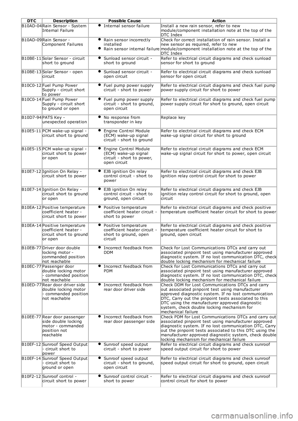
DT CDescriptionPossible CauseAction
B10AD-04Rain Sens or - Sys t emInt ernal FailureInternal s ens or fail ureIns t al l a new rain s ens or, refer to newmodule/component i nst all at ion not e at t he top of t heDTC Index
B10AD-09Rain Sens or -Component Fail uresRai n s ens or incorrect lyi nst all edRai n s ens or int ernal fail ure
Check for correct ins tal lati on of rai n s ens or. Ins tall anew s ens or as requi red, refer t o newmodule/component i nst all at ion not e at t he top of t heDTC Index
B10BE-11Solar Sens or - circui ts hort t o groundSunload s ens or circui t -s hort t o groundRefer to electrical ci rcuit diagrams and check s unl oads ens or for s hort t o ground
B10BE-13Solar Sens or - opencircui tSunload s ens or circui t -open circui tRefer to electrical ci rcuit diagrams and check s unl oads ens or for open circuit
B10C0-12Fuel Pump PowerSuppl y - circui t shortt o power
Fuel pump power supplyci rcuit - s hort t o powerRefer to electrical ci rcuit diagrams and check fuel pumppower s upply circui t for s hort t o power
B10C0-14Fuel Pump PowerSuppl y - circui t shortt o ground or open
Fuel pump power supplyci rcuit - s hort t o ground,open circui t
Refer to electrical ci rcuit diagrams and check fuel pumppower s upply circui t for s hort t o ground, open ci rcuit
B10D7-94PATS Key -unexpected operat ionNo res pons e fromt rans ponder i n keyRepl ace key
B10E5-11PCM wake-up si gnal -circui t short to groundEngine Cont rol Module(ECM) wake-up s ignalci rcuit - s hort t o ground
Refer to electrical ci rcuit diagrams and check ECMwake-up s ignal ci rcuit for short to ground
B10E5-15PCM wake-up si gnal -circui t short to poweror open
Engine Cont rol Module(ECM) wake-up s ignalci rcuit - s hort t o power,open circui t
Refer to electrical ci rcuit diagrams and check ECMwake-up s ignal ci rcuit for short to power, open circui t
B10E7-12Igni ti on On Relay -circui t short to powerEJB i gni ti on On relaycontrol ci rcuit - s hort t opower
Refer to electrical ci rcuit diagrams and check EJBignit ion relay control ci rcuit for s hort t o power
B10E7-14Igni ti on On Relay -circui t short to groundor open
EJB i gni ti on On relaycontrol ci rcuit - s hort t oground, open circuit
Refer to electrical ci rcuit diagrams and check EJBignit ion relay control ci rcuit for s hort t o ground, openci rcuit
B10EA-12Posi ti ve t emperaturecoeffi ci ent heat er -circui t short to power
Pos it ive t emperat urecoefficient heater circuit -s hort t o power
Refer to electrical ci rcuit diagrams and check posi ti vetemperat ure coeffici ent heater circui t for s hort t o power
B10EA-14Posi ti ve t emperaturecoeffi ci ent heat er -circui t short to groundor open
Pos it ive t emperat urecoefficient heater circuit -s hort t o ground, openci rcuit
Refer to electrical ci rcuit diagrams and check posi ti vetemperat ure coeffici ent heater circui t for s hort t oground, open circui t
B10EB-77Driver door doubl elocking mot or -commanded pos i ti onnot reachabl e
Incorrect feedback fromDDMCheck for Los t Communicati ons DTCs and carry outass ociated pi npoi nt tes t us ing manufacturer approveddiagnos t ic s ys tem. If no los t communicati on DTC, checkdoubl e locking mechani s m for mechanical fail ureB10EC-77Pass enger doordoubl e l ocking mot or- commanded pos i ti onnot reachabl e
Incorrect feedback fromPDMCheck for Los t Communicati ons DTCs and carry outass ociated pi npoi nt tes t us ing manufacturer approveddiagnos t ic s ys tem. If no los t communicati on DTC, checkdoubl e locking mechani s m for mechanical fail ureB10ED-77Rear door dri ver s i dedoubl e l ocking mot or- commanded pos i ti onnot reachabl e
Incorrect feedback fromrear door dri ver s i deCheck DDM for Los t Communicat ions DTCs and carryout as s oci ated pi npoi nt t es t usi ng manufacturerapproved di agnos ti c s yst em. If no los t communi cat ionDTC, Carry out t he pinpoint t est s as sociat ed t o thi sDTC us ing t he manufacturer approved diagnos ti cs ys t em, check doubl e locking mechanis m formechanical fai lure
B10EE-77Rear door pas sengers ide double l ocki ngmot or - commandedposi ti on notreachabl e
Incorrect feedback fromrear door pas senger si deCheck PDM for Lost Communi cat ions DTCs and carry outass ociated pi npoi nt tes t us ing manufacturer approveddiagnos t ic s ys tem. If no los t communicati on DTC, Carryout the pi npoint t es ts as s oci at ed t o t his DTC us ing themanufacturer approved diagnost ic sys tem, check doublelocki ng mechani sm for mechanical fail ureB10EF-12Sunroof Speed Out put- circui t short topower
Sunroof s peed out putci rcuit - s hort t o powerRefer to electrical ci rcuit diagrams and check s unroofs peed out put circui t for s hort t o power
B10EF-14Sunroof Speed Out put- circui t short toground or open
Sunroof s peed out putci rcuit - s hort t o ground,open circui t
Refer to electrical ci rcuit diagrams and check s unroofs peed out put circui t for s hort t o ground, open ci rcuit
B10F2-12Sunroof cont rol -circui t short to powerSunroof cont rol circui t -s hort t o powerRefer to electrical ci rcuit diagrams and check s unroofcont rol circuit for s hort to power
Page 73 of 3229
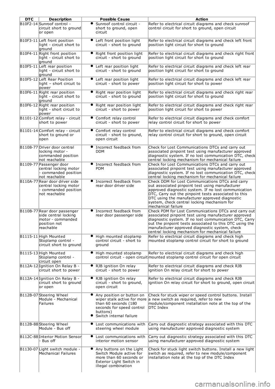
DT CDescriptionPossible CauseAction
B10F2-14Sunroof cont rol -circui t short to groundor open
Sunroof cont rol circui t -s hort t o ground, openci rcuit
Refer to electrical ci rcuit diagrams and check s unroofcont rol circuit for s hort to ground, open circui t
B10F3-11Left front posi ti onli ght - ci rcuit s hort t oground
Left front pos it ion l ightci rcuit - s hort t o groundRefer to electrical ci rcuit diagrams and check left frontpos i ti on li ght circui t for s hort t o ground
B10F4-11Right front posi ti onli ght - ci rcuit s hort t oground
Ri ght front pos it ion l ightci rcuit - s hort t o groundRefer to electrical ci rcuit diagrams and check right frontpos i ti on li ght circui t for s hort t o ground
B10F5-11Left rear pos it ionli ght - ci rcuit s hort t oground
Left rear pos i ti on li ghtci rcuit - s hort t o groundRefer to electrical ci rcuit diagrams and check left rearpos i ti on li ght circui t for s hort t o ground
B10F5-12Left Rear Pos i ti onli ght – s hort circuit topower
Left rear pos i ti on li ghtci rcuit - s hort t o powerRefer to electrical ci rcuit diagrams and check left rearpos i ti on li ght circui t for s hort t o power
B10F6-11Right rear pos it ionli ght - ci rcuit s hort t oground
Ri ght rear pos i ti on li ghtci rcuit - s hort t o groundRefer to electrical ci rcuit diagrams and check right rearpos i ti on li ght circui t for s hort t o ground
B10F6-12Right rear pos it ionli ght - short ci rcuit t opower
Ri ght rear pos i ti on li ghtci rcuit - s hort t o powerRefer to electrical ci rcuit diagrams and check right rearpos i ti on li ght circui t for s hort t o power
B1101-12Comfort rel ay - circuits hort t o powerComfort relay controlci rcuit - s hort t o powerRefer to electrical ci rcuit diagrams and check comfortrel ay cont rol ci rcuit for short to power
B1101-14Comfort rel ay - circuits hort t o ground oropen
Comfort relay controlci rcuit - s hort t o ground,open circui t
Refer to electrical ci rcuit diagrams and check comfortrel ay cont rol ci rcuit for short to ground, open circui t
B1108-77Driver door cent rallocking mot or -commanded pos i ti onnot reachabl e
Incorrect feedback fromDDMCheck for Los t Communicati ons DTCs and carry outass ociated pi npoi nt tes t us ing manufacturer approveddiagnos t ic s ys tem. If no los t communicati on DTC, checkcent ral locking mechani s m for mechanical fai lure
B1109-77Pass enger doorcent ral l ocking motor- commanded pos i ti onnot reachabl e
Incorrect feedback fromPDMCheck for Los t Communicati ons DTCs and carry outass ociated pi npoi nt tes t us ing manufacturer approveddiagnos t ic s ys tem. If no los t communicati on DTC, checkcent ral locking mechani s m for mechanical fai lure
B110A-77Rear door dri ver s i decent ral l ocking motor- commanded pos i ti onnot reachabl e
Incorrect feedback fromrear door dri ver s i deCheck DDM for Los t Communicat ions DTCs and carryout as s oci ated pi npoi nt t es t usi ng manufacturerapproved di agnos ti c s yst em. If no los t communi cat ionDTC, Carry out t he pinpoint t est s as sociat ed t o thi sDTC us ing t he manufacturer approved diagnos ti cs ys t em, check cent ral l ocking mechanis m formechanical fai lure
B110B-77Rear door pas sengers ide central locki ngmot or - commandedposi ti on notreachabl e
Incorrect feedback fromrear door pas senger si deCheck PDM for Lost Communi cat ions DTCs and carry outass ociated pi npoi nt tes t us ing manufacturer approveddiagnos t ic s ys tem. If no los t communicati on DTC, Carryout the pi npoint t es ts as s oci at ed t o t his DTC us ing themanufacturer approved diagnost ic sys tem, checkcent ral locking mechani s m for mechanical fai lure
B1115-11High Mount edStopl amp cont rol -circui t short to ground
Hi gh mounted st oplampcontrol ci rcuit - s hort t oground
Refer to electrical ci rcuit diagrams and check highmounted s t opl amp cont rol circui t for s hort t o ground
B1115-13High Mount edStopl amp cont rol -circui t open
Hi gh mounted st oplampcontrol ci rcuit - open circui tRefer to electrical ci rcuit diagrams and check highmounted s t opl amp cont rol circui t for open circui t
B112A-12Igni ti on On Relay B -circui t short to powerRJB i gni ti on On relayci rcuit - s hort t o powerRefer to electrical ci rcuit diagrams and check RJBignit ion O n rel ay ci rcuit for short to power
B112A-14Igni ti on On Relay B -circui t short to groundor open
RJB i gni ti on On relayci rcuit - s hort t o ground,open circui t
Refer to electrical ci rcuit diagrams and check RJBignit ion O n rel ay ci rcuit for short to ground, open circui t
B112B-07Steering W heelModule - MechanicalFailures
Any pos it ion or but ton onwiper st alk act ive for moret han 60 s econds (180s econds for s peed controlbut tons )Swi tch i nternal fai lure
Check for st uck wiper or speed control but tons . Ins tal la new s wi tch as requi red, refer to newmodule/component i nst all at ion not e at t he top of t heDTC Index
B112B-88Steering W heelModule - Bus offLos t communicat ions wi ths t eering wheel moduleCarry out di agnos ti c s trategy as s ociat ed wi th t his DTCusi ng manufacturer approved diagnos ti c sys t em
B112C-88Int eri or Moti on Sens or- Bus offLos t communicat ions wi thi nterior mot ion s ensorCarry out di agnos ti c s trategy as s ociat ed wi th t his DTCusi ng manufacturer approved diagnos ti c sys t em
B1130-07Light s wit ch module -Mechani cal FailuresAny but tons on t he LightSwi tch Module act ive formore t han 60 s econds orExt erior Light Swit ch ini ll egal combinati on
Check for st uck li ght s wi tch butt ons. Ins tall a new li ghts wit ch as required, refer t o new module/componentins tal lati on note at the t op of the DTC Index
Page 74 of 3229
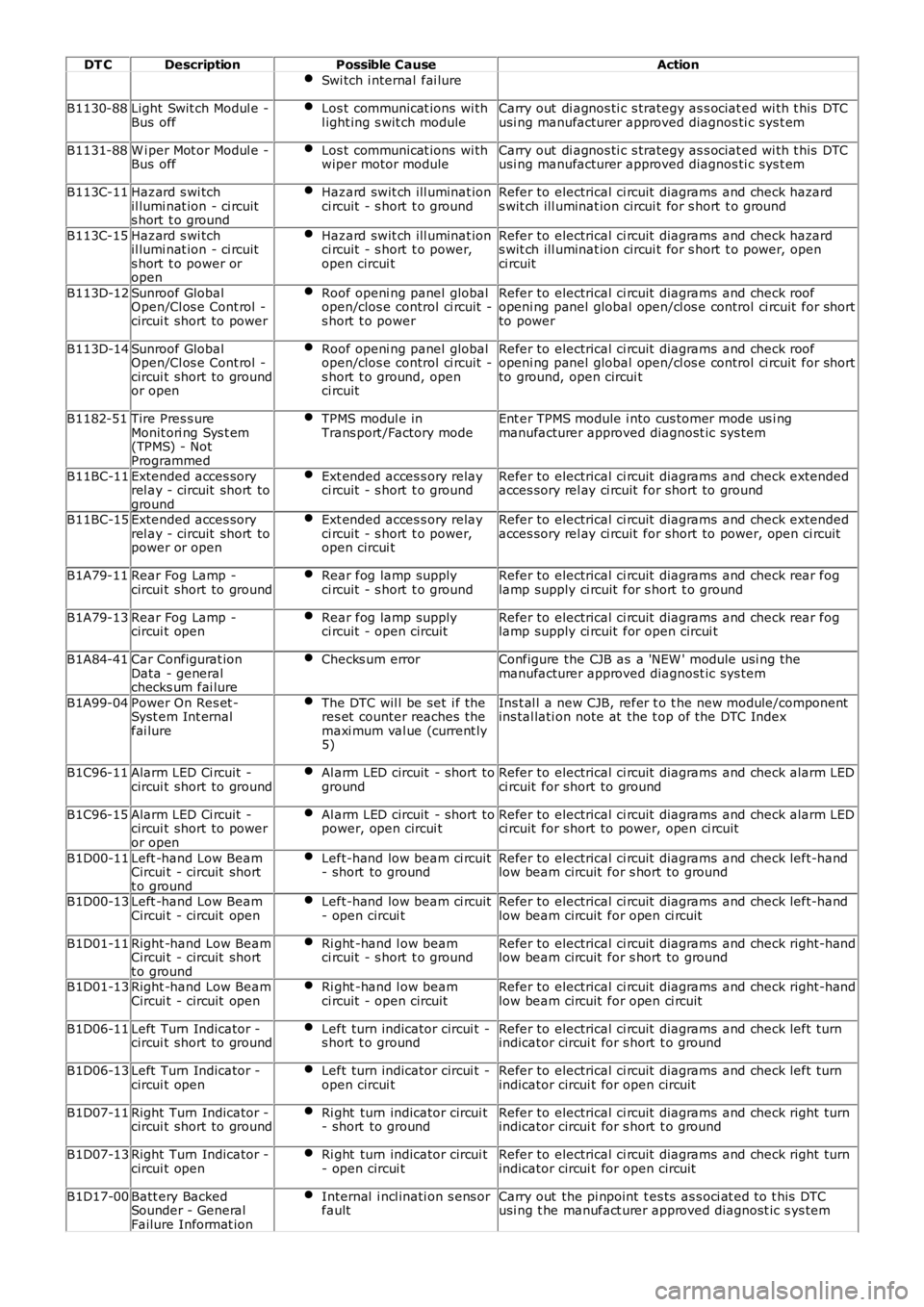
DT CDescriptionPossible CauseAction
Swi tch i nternal fai lure
B1130-88Light Swit ch Modul e -Bus offLos t communicat ions wi thl ight ing s wit ch moduleCarry out di agnos ti c s trategy as s ociat ed wi th t his DTCusi ng manufacturer approved diagnos ti c sys t em
B1131-88W i per Mot or Modul e -Bus offLos t communicat ions wi thwiper motor moduleCarry out di agnos ti c s trategy as s ociat ed wi th t his DTCusi ng manufacturer approved diagnos ti c sys t em
B113C-11Hazard s wi tchil lumi nat ion - ci rcuits hort t o ground
Hazard swit ch ill uminat ionci rcuit - s hort t o groundRefer to electrical ci rcuit diagrams and check hazards wit ch ill uminat ion circui t for s hort t o ground
B113C-15Hazard s wi tchil lumi nat ion - ci rcuits hort t o power oropen
Hazard swit ch ill uminat ionci rcuit - s hort t o power,open circui t
Refer to electrical ci rcuit diagrams and check hazards wit ch ill uminat ion circui t for s hort t o power, openci rcuit
B113D-12Sunroof GlobalOpen/Cl os e Cont rol -circui t short to power
Roof openi ng panel globalopen/clos e control ci rcuit -s hort t o power
Refer to electrical ci rcuit diagrams and check roofopeni ng panel global open/cl os e control ci rcuit for shortto power
B113D-14Sunroof GlobalOpen/Cl os e Cont rol -circui t short to groundor open
Roof openi ng panel globalopen/clos e control ci rcuit -s hort t o ground, openci rcuit
Refer to electrical ci rcuit diagrams and check roofopeni ng panel global open/cl os e control ci rcuit for shortto ground, open circui t
B1182-51Tire Pres s ureMonit ori ng Sys t em(TPMS) - NotProgrammed
TPMS modul e inTrans port /Factory modeEnt er TPMS module i nto cus tomer mode us i ngmanufacturer approved diagnost ic sys tem
B11BC-11Extended acces soryrel ay - circuit short toground
Ext ended acces s ory relayci rcuit - s hort t o groundRefer to electrical ci rcuit diagrams and check extendedacces sory rel ay ci rcuit for short to ground
B11BC-15Extended acces soryrel ay - circuit short topower or open
Ext ended acces s ory relayci rcuit - s hort t o power,open circui t
Refer to electrical ci rcuit diagrams and check extendedacces sory rel ay ci rcuit for short to power, open ci rcuit
B1A79-11Rear Fog Lamp -circui t short to groundRear fog lamp supplyci rcuit - s hort t o groundRefer to electrical ci rcuit diagrams and check rear foglamp supply ci rcuit for s hort t o ground
B1A79-13Rear Fog Lamp -circui t openRear fog lamp supplyci rcuit - open circuitRefer to electrical ci rcuit diagrams and check rear foglamp supply ci rcuit for open circui t
B1A84-41Car Configurat ionData - generalchecks um fai lure
Checks um errorConfigure the CJB as a 'NEW ' module usi ng t hemanufacturer approved diagnost ic sys tem
B1A99-04Power On Res et -Syst em Int ernalfai lure
The DTC wil l be set i f theres et counter reaches themaxi mum val ue (current ly5)
Ins t al l a new CJB, refer t o t he new module/componentins tal lati on note at the t op of the DTC Index
B1C96-11Alarm LED Ci rcuit -circui t short to groundAl arm LED circuit - short togroundRefer to electrical ci rcuit diagrams and check alarm LEDci rcuit for short to ground
B1C96-15Alarm LED Ci rcuit -circui t short to poweror open
Al arm LED circuit - short topower, open circui tRefer to electrical ci rcuit diagrams and check alarm LEDci rcuit for short to power, open ci rcuit
B1D00-11Left -hand Low BeamCircui t - circuit shortt o ground
Left-hand low beam ci rcuit- short to groundRefer to electrical ci rcuit diagrams and check left-handlow beam circuit for s hort to ground
B1D00-13Left -hand Low BeamCircui t - circuit openLeft-hand low beam ci rcuit- open circui tRefer to electrical ci rcuit diagrams and check left-handlow beam circuit for open ci rcuit
B1D01-11Right -hand Low BeamCircui t - circuit shortt o ground
Ri ght -hand l ow beamci rcuit - s hort t o groundRefer to electrical ci rcuit diagrams and check right-handlow beam circuit for s hort to ground
B1D01-13Right -hand Low BeamCircui t - circuit openRi ght -hand l ow beamci rcuit - open circuitRefer to electrical ci rcuit diagrams and check right-handlow beam circuit for open ci rcuit
B1D06-11Left Turn Indicator -circui t short to groundLeft turn indicator circui t -s hort t o groundRefer to electrical ci rcuit diagrams and check left turnindicator circui t for s hort t o ground
B1D06-13Left Turn Indicator -circui t openLeft turn indicator circui t -open circui tRefer to electrical ci rcuit diagrams and check left turnindicator circui t for open circuit
B1D07-11Right Turn Indicator -circui t short to groundRi ght turn indicator circui t- short to groundRefer to electrical ci rcuit diagrams and check right turnindicator circui t for s hort t o ground
B1D07-13Right Turn Indicator -circui t openRi ght turn indicator circui t- open circui tRefer to electrical ci rcuit diagrams and check right turnindicator circui t for open circuit
B1D17-00Batt ery BackedSounder - GeneralFailure Informat ion
Internal i ncl inati on s ens orfaultCarry out the pi npoint t es ts as s oci at ed t o t his DTCusi ng t he manufact urer approved diagnost ic s ys tem
Page 75 of 3229
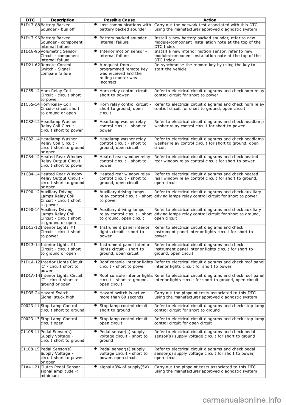
DT CDescriptionPossible CauseAction
B1D17-88Batt ery BackedSounder - bus offLos t communicat ions wi thbat tery backed s ounderCarry out the net work t est as s oci ated wi th thi s DTCusi ng t he manufact urer approved diagnost ic s ys tem
B1D17-96Batt ery BackedSounder - componentint ernal fai lure
Bat tery backed s ounder -i nternal failureIns t al l a new bat tery backed s ounder, refer t o newmodule/component i nst all at ion not e at t he top of t heDTC IndexB1D18-96Volumet ri c Sens orCircui t - componentint ernal fai lure
Interior mot ion s ensor -i nternal failureIns t al l a new i nteri or moti on s ens or, refer t o newmodule/component i nst all at ion not e at t he top of t heDTC Index
B1D21-62Remote Cont rolSwit ch - Signalcompare failure
A request from aprogrammed remote keywas recei ved and theroll ing count er wasi ncorrect
Re-s ynchroni se the remote key by us i ng the key t os tart the vehicle
B1C55-12Horn Rel ay CoilCircui t - circuit shortt o power
Horn rel ay cont rol circui t -s hort t o powerRefer to electrical ci rcuit diagrams and check horn relaycont rol circuit for s hort to power
B1C55-14Horn Rel ay CoilCircui t- ci rcuit s hortt o ground or open
Horn rel ay cont rol circui t -s hort t o ground, openci rcuit
Refer to electrical ci rcuit diagrams and check horn relaycont rol circuit for s hort to ground, open circui t
B1C82-12Headlamp W asherRelay Coil Ci rcuit -circui t short to power
Headlamp washer rel aycontrol ci rcuit - s hort t opower
Refer to electrical ci rcuit diagrams and check headl ampwasher rel ay cont rol circui t for s hort t o power
B1C82-14Headlamp W asherRelay Coil Ci rcuit -circui t short to groundor open
Headlamp washer rel aycontrol ci rcuit - s hort t oground, open circuit
Refer to electrical ci rcuit diagrams and check headl ampwasher rel ay cont rol circui t for s hort t o ground, openci rcuit
B1C84-12Heated Rear W i ndowRelay Out put Ci rcuit -circui t short to power
Heat ed rear wi ndow relaycontrol ci rcuit - s hort t opower
Refer to electrical ci rcuit diagrams and check heatedrear window relay control ci rcuit for s hort t o power
B1C84-14Heated Rear W i ndowRelay Out put Ci rcuit -circui t short to groundor open
Heat ed rear wi ndow relaycontrol ci rcuit - s hort t oground, open circuit
Refer to electrical ci rcuit diagrams and check heatedrear window relay control ci rcuit for s hort t o ground,open ci rcuit
B1C90-12Auxili ary DrivingLamps Relay CoilCircui t - circuit shortt o power
Auxil iary dri vi ng lampsrelay control ci rcuit - s hortt o power
Refer to electrical ci rcuit diagrams and check auxi li arydri vi ng lamps relay control ci rcuit for s hort t o power
B1C90-14Auxili ary DrivingLamps Relay CoilCircui t - circuit shortt o ground or open
Auxil iary dri vi ng lampsrelay control ci rcuit - s hortt o ground, open circuit
Refer to electrical ci rcuit diagrams and check auxi li arydri vi ng lamps relay control ci rcuit for s hort t o ground,open ci rcuit
B1D13-12Int eri or Li ght s #1Circui t - circuit shortt o power
Ins trument panel int eriorl ight s ci rcuit - s hort t opower
Refer to electrical ci rcuit diagrams and checkins trument panel int eri or l ights ci rcuit for short topower
B1D13-14Int eri or Li ght s #1Circui t - circuit shortt o ground or open
Ins trument panel int eriorl ight s ci rcuit - s hort t oground, open circuit
Refer to electrical ci rcuit diagrams and checkins trument panel int eri or l ights ci rcuit for short toground, open circui t
B1D1A-12Int eri or Li ght s Ci rcuit'C' - circui t s hort topower
Roof cons ole int erior l ightsci rcuit - s hort t o powerRefer to electrical ci rcuit diagrams and check roof panelint erior l ights ci rcuit for s hort t o power
B1D1A-14Int eri or Li ght s Ci rcuit'C' - circui t s hort toground or open
Roof cons ole int erior l ightsci rcuit - s hort t o ground,open circui t
Refer to electrical ci rcuit diagrams and check roof panelint erior l ights ci rcuit for s hort t o ground, open circuit
B1D35-24Hazard Swi tch -Signal st uck highHazard swit ch is acti vemore t han 60 s econdsCarry out the pi npoint t es ts as s oci at ed t o t his DTCusi ng t he manufact urer approved diagnost ic s ys tem
C0023-11Stop Lamp Cont rol -circui t short to groundSt op lamp cont rol circui t -s hort t o groundRefer to electrical ci rcuit diagrams and check s top lampcont rol circuit for s hort to ground
C0023-13Stop Lamp Cont rol -circui t openSt op lamp cont rol circui t -open circui tRefer to electrical ci rcuit diagrams and check s top lampcont rol circuit for open ci rcuit
C1108-11Pedal Sens or(s )Suppl y Volt age -circui t short to ground
Pedal sens or(s ) supplyvolt age circui t - short toground
Refer to electrical ci rcuit diagrams and check pedals ens or(s ) supply vol tage circui t for s hort t o ground
C1108-15Pedal Sens or(s )Suppl y Volt age -circui t short to poweror open
Pedal sens or(s ) supplyvolt age circui t - short topower, open circui t
Refer to electrical ci rcuit diagrams and check pedals ens or(s ) supply vol tage circui t for s hort t o power,open ci rcuit
C1A41-21Clut ch Pedal Sensor -s ignal amplit ude