2006 LAND ROVER FRELANDER 2 roof
[x] Cancel search: roofPage 2127 of 3229
Publi s hed: 11-May-2011
Interior Trim and Ornamentation - HeadlinerVehicles Without: Tilting Roof
Opening Panel
Removal and Inst all ati on
Removal
CAUTION: Make s ure that the wiring harnes s es are correct ly locat ed.
• NOTE: If a headl iner is t o be replaced, i t is i mperat ive t hat the was her hos e and wi ri ng harnes s are i nst all ed to theirori ginal pos it ions . Fai lure to fol low t hese ins truct ions may impede t he s ide air curt ain modul e performance.
• NOTE: Note the pos it ion of t he wi ri ng harness es t o aid ins tall ati on.
Remove both A-pil lar t ri m panels .
Refer t o: A-Pil lar Tri m Panel (501-05 Int erior Trim andOrnament ati on, Removal and Ins tal lat ion).
1.
Remove both B-pil lar upper t ri m panels .
Refer t o: B-Pil lar Upper Trim Panel (501-05 Interior Tri m andOrnament ati on, Removal and Ins tal lat ion).
2.
Remove both C-pil lar t ri m panels .
Refer t o: C-Pil lar Tri m Panel (501-05 Int erior Trim andOrnament ati on, Removal and Ins tal lat ion).
3.
Remove both D-pil lar upper t rim panels .
Refer t o: D-Pi llar Trim Panel (501-05 Int eri or Trim andOrnament ati on, Removal and Ins tal lat ion).
4.
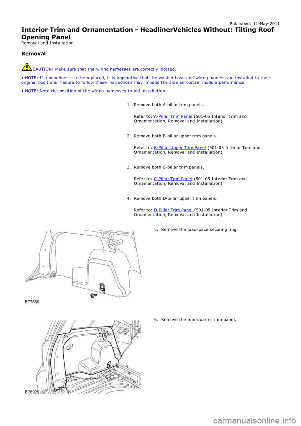
Remove t he loadspace s ecuring ring.5.
Remove t he rear quart er t ri m panel.6.
Page 2136 of 3229
Publi s hed: 11-May-2011
Interior Trim and Ornamentation - HeadlinerVehicles With: Tilting Roof
Opening Panel
Removal and Inst all ati on
Removal CAUTION: Make s ure that the wiring harnes s es are correct ly locat ed.
• NOTE: If a headl iner is t o be replaced, i t is i mperat ive t hat the was her hos e and wi ri ng harnes s are i nst all ed to their
ori ginal pos it ions . Fai lure to fol low t hese ins truct ions may impede t he s ide air cur t ain modul e performance.
• NOTE: Note the pos it ion of t he wi ri ng harness es t o aid ins tall ati on.
Remove both A-pil lar t ri m panels .
Refer t o: A-Pil lar Tri m Panel (501-05 Int erior Trim and
Ornament ati on, Removal and Ins tal lat ion).
1.
Remove both B-pil lar upper t ri m panels .
Refer t o: B-Pil lar Upper Trim Panel (501-05 Interior Tri m and
Ornament ati on, Removal and Ins tal lat ion).
2.
Remove both C-pil lar t ri m panels .
Refer t o: C-Pil lar Tri m Panel (501-05 Int erior Trim and
Ornament ati on, Removal and Ins tal lat ion).
3.
Remove both D-pil lar upper t rim panels .
Refer t o: D-Pi llar Trim Panel (501-05 Int eri or Trim and
Ornament ati on, Removal and Ins tal lat ion).
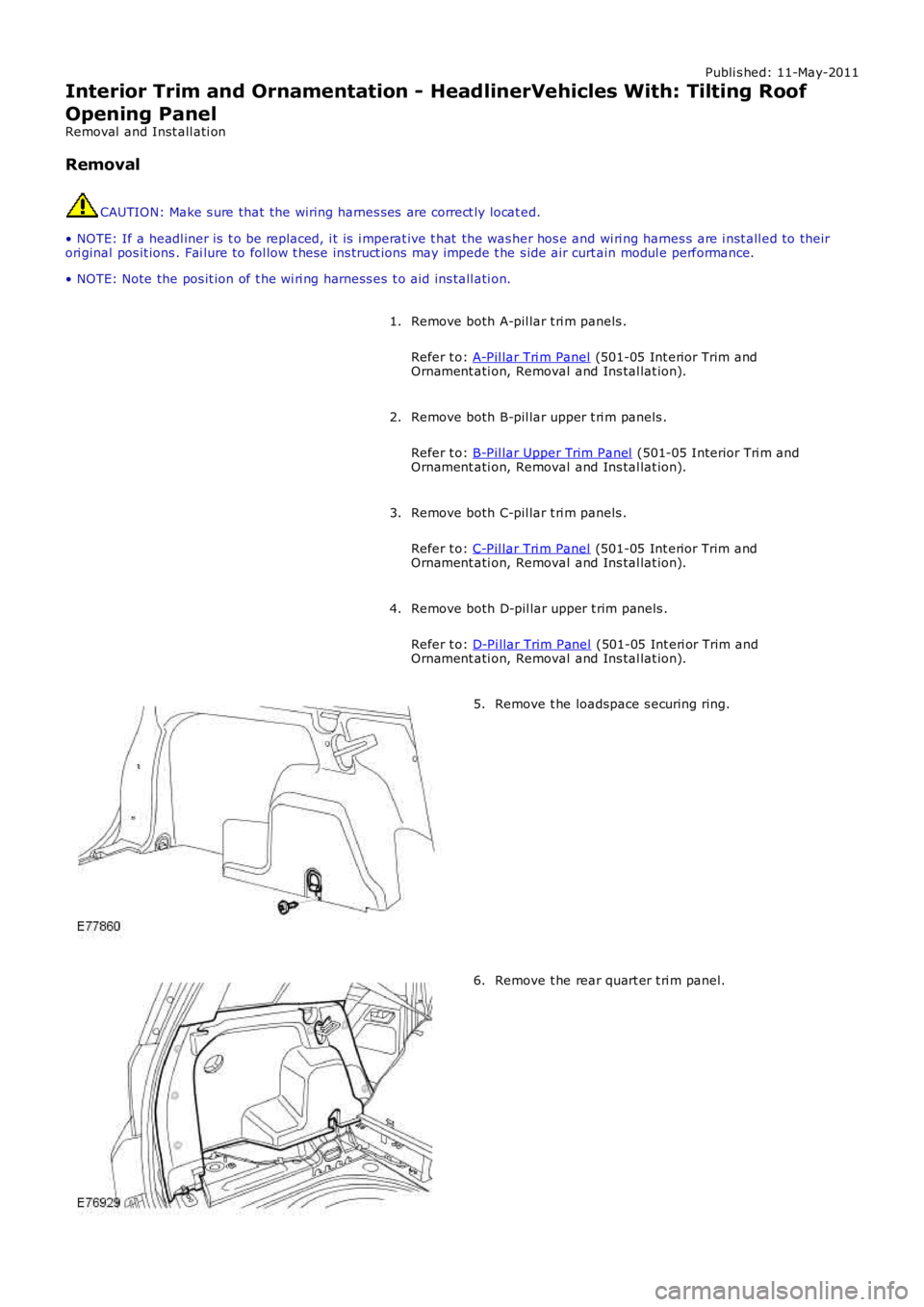
4. Remove t he loadspace s ecuring ring.
5. Remove t he rear quart er t ri m panel.
6.
Page 2142 of 3229
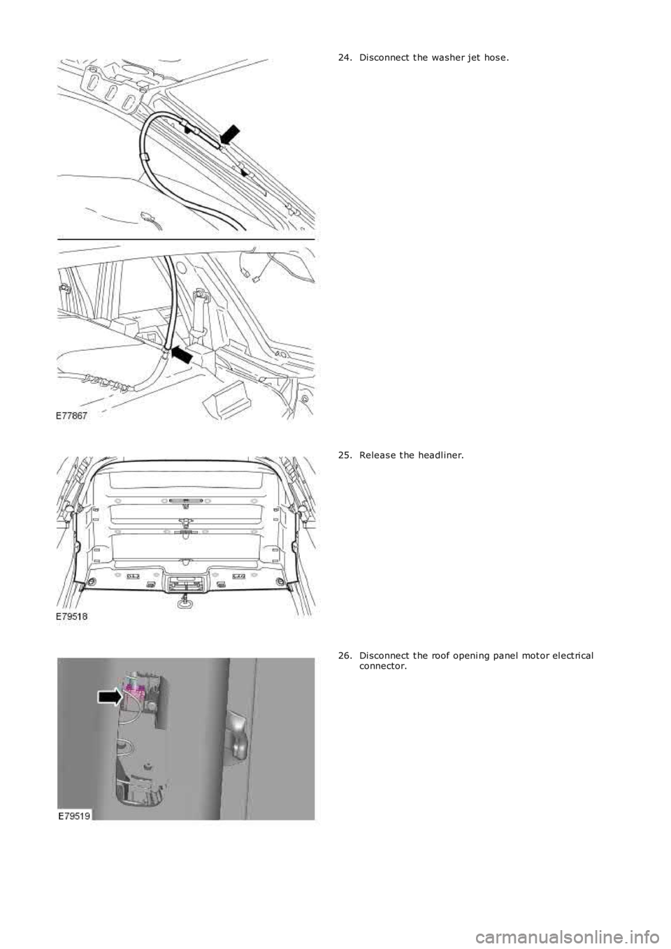
Di sconnect t he washer jet hos e.
24. Releas e t he headl iner.
25. Di sconnect t he roof openi ng panel mot or el ect ri cal
connector.
26.
Page 2144 of 3229
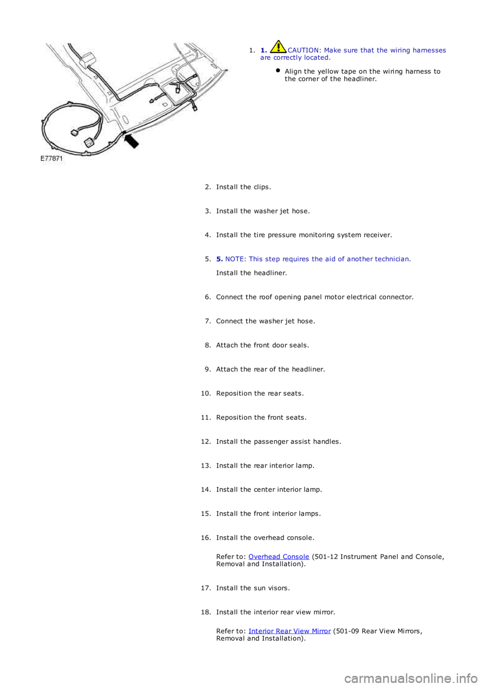
1. CAUTION: Make s ure that the wiring harnes s es
are correctl y located.
Ali gn t he yel low tape on t he wi ri ng harness to
t he corner of t he headl iner. 1.
Inst all t he cl ips .
2.
Inst all t he washer jet hos e.
3.
Inst all t he ti re pres sure monit ori ng s ys t em receiver.
4.
5. NOTE: Thi s s tep requires the ai d of anot her techni ci an.
Inst all t he headl iner.
5.
Connect t he roof openi ng panel mot or elect rical connect or.
6.
Connect t he was her jet hos e.
7.
At tach t he front door s eal s .
8.
At tach t he rear of the headli ner.
9.
Reposi ti on the rear s eat s .
10.
Reposi ti on the front s eats .
11.
Inst all t he pas s enger as s is t handl es .
12.
Inst all t he rear int eri or l amp.
13.
Inst all t he cent er interior lamp.
14.
Inst all t he front interior lamps .
15.
Inst all t he overhead cons ol e.
Refer t o: Overhead Cons ole (501-12 Ins trument Panel and Cons ole,
Removal and Ins tall ati on).
16.
Inst all t he s un vi s ors .
17.
Inst all t he int erior rear vi ew mi rror.
Refer t o: Int erior Rear View Mirror (501-09 Rear Vi ew Mi rrors ,
Removal and Ins tall ati on).
18.
Page 2160 of 3229
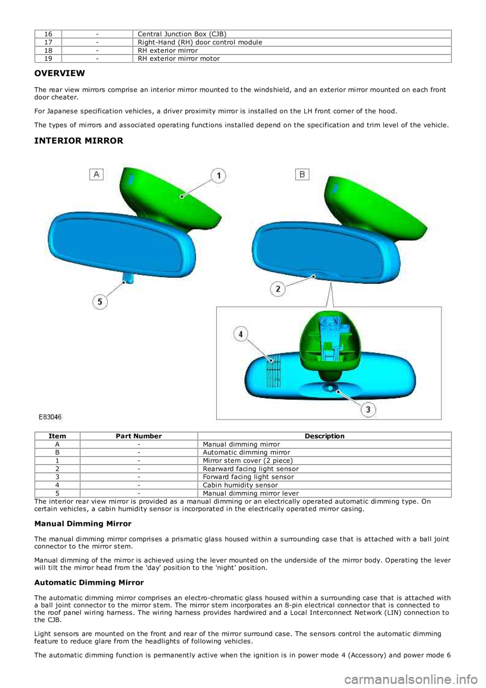
16-Central Juncti on Box (CJB)
17-Ri ght -Hand (RH) door control modul e
18-RH ext eri or mirror19-RH ext eri or mirror mot or
OVERVIEW
The rear view mirrors compris e an int erior mi rror mount ed t o t he winds hield, and an exterior mi rror mount ed on each frontdoor cheater.
For Japanes e s peci fi cat ion vehicles , a driver proximi ty mirror is ins tall ed on t he LH front corner of t he hood.
The t ypes of mi rrors and as s oci at ed operat ing funct ions ins tal led depend on t he specificati on and trim level of the vehicle.
INTERIOR MIRROR
ItemPart NumberDescription
A-Manual dimming mirrorB-Aut omati c dimming mirror
1-Mirror s tem cover (2 piece)
2-Rearward faci ng li ght sens or3-Forward faci ng li ght sens or
4-Cabi n humidi ty s ens or
5-Manual dimming mirror leverThe int eri or rear vi ew mi rror is provi ded as a manual di mmi ng or an electrically operated aut omat ic di mmi ng t ype. Oncert ai n vehicles , a cabi n humidi ty s ens or i s i ncorporat ed i n the el ect ri cal ly operated mi rror cas ing.
Manual Dimming Mirror
The manual di mmi ng mirror compri s es a pri smati c glas s hous ed wi thi n a s urroundi ng cas e t hat is at tached wit h a bal l jointconnector t o t he mirror s t em.
Manual di mming of t he mi rror is achieved usi ng t he lever mount ed on t he unders ide of t he mirror body. Operati ng the leverwil l ti lt t he mi rror head from t he 'day' pos it ion t o t he 'ni ght ' pos it ion.
Automatic Dimming Mirror
The automat ic di mming mirror compri ses an el ect ro-chromati c glas s housed wit hi n a s urroundi ng cas e that is at t ached wi tha ball joint connector t o t he mirror s t em. The mirror s tem incorporat es an 8-pi n electrical connect or that i s connected t ot he roof panel wi ri ng harness . The wi ring harnes s provi des hardwired and a Local Interconnect Net work (LIN) connect ion t ot he CJB.
Light s ens ors are mount ed on t he front and rear of t he mi rror surround case. The s ensors cont rol t he automat ic dimmingfeat ure t o reduce gl are from the headli ght s of fol lowi ng vehi cl es .
The automat ic di mming funct ion is permanent ly acti ve when t he ignit ion i s in power mode 4 (Access ory) and power mode 6
Page 2235 of 3229
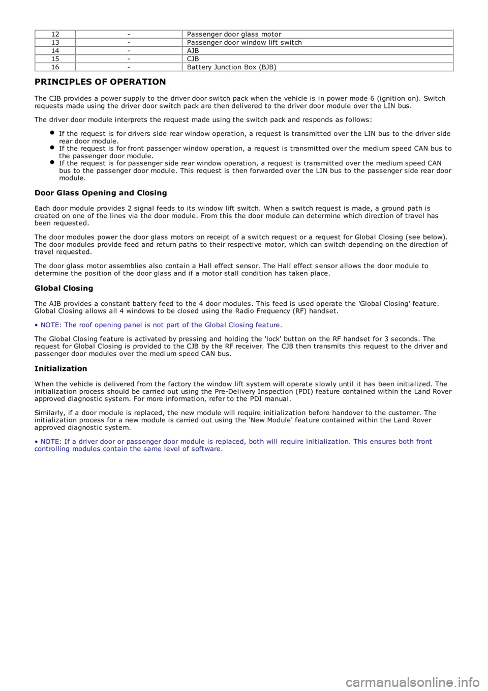
12-Pass enger door glas s mot or
13-Pass enger door wi ndow lift s wit ch
14-AJB15-CJB
16-Batt ery Junct ion Box (BJB)
PRINCIPLES OF OPERATION
The CJB provides a power s uppl y t o the driver door s wi tch pack when t he vehi cl e is in power mode 6 (i gni ti on on). Swit chreques ts made us i ng the driver door s wi tch pack are t hen deli vered to the driver door module over t he LIN bus .
The dri ver door module i nterprets t he reques t made us ing t he s wit ch pack and res ponds as follows :
If the reques t is for dri vers s ide rear window operat ion, a reques t is t rans mit t ed over t he LIN bus to the driver si derear door modul e.If the reques t is for front pas s enger wi ndow operati on, a reques t i s t ransmit ted over the medium speed CAN bus t ot he pas s enger door modul e.If the reques t is for pass enger s i de rear window operat ion, a reques t is trans mi tt ed over the medi um s peed CANbus to the pas s enger door modul e. Thi s request is t hen forwarded over t he LIN bus t o the pas s enger s ide rear doormodule.
Door G lass Opening and Closing
Each door module provides 2 s ignal feeds t o it s wi ndow li ft s wit ch. W hen a s wi tch reques t is made, a ground pat h i screated on one of the l ines via the door module. From this the door module can det ermi ne which direct ion of t ravel hasbeen request ed.
The door modul es power t he door gl ass motors on receipt of a s wi tch reques t or a reques t for Global Clos ing (s ee below).The door modul es provide feed and ret urn pat hs to their respecti ve motor, which can s wit ch depending on t he direct ion oft ravel reques t ed.
The door gl ass motor as sembl ies als o contai n a Hal l effect s ens or. The Hal l effect sens or all ows the door module todetermine t he pos it ion of t he door glas s and i f a mot or st all condi ti on has taken place.
Global Closing
The AJB provides a cons tant batt ery feed to the 4 door modules . This feed is us ed operat e t he 'Gl obal Clos ing' feat ure.Global Clos ing al lows all 4 windows t o be clos ed usi ng t he Radi o Frequency (RF) hands et.
• NOTE: The roof opening panel i s not part of the Global Cl osi ng feat ure.
The Global Clos ing feat ure is acti vat ed by pres s ing and hol di ng t he 'l ock' but ton on the RF hands et for 3 s econds . Thereques t for Global Clos ing i s provided t o t he CJB by t he RF receiver. The CJB t hen trans mi ts thi s request t o t he dri ver andpass enger door modules over the medi um s peed CAN bus .
Initialization
W hen t he vehicle i s deli vered from t he fact ory t he wi ndow lift s yst em will operat e slowl y unt il i t has been init ial ized. Theini ti al izati on process should be carri ed out usi ng the Pre-Del ivery Ins pecti on (PDI) feat ure contai ned wit hin t he Land Roverapproved diagnos t ic s yst em. For more informati on, refer t o t he PDI manual .
Simi larly, if a door module is repl aced, t he new module will requi re init iali zat ion before handover t o t he cus t omer. Theini ti al izati on process for a new modul e i s carri ed out us i ng the 'New Module' feat ure contai ned wit hi n t he Land Roverapproved diagnos t ic s yst em.
• NOTE: If a dri ver door or pas s enger door modul e i s replaced, bot h wi ll require i niti ali zat ion. Thi s ens ures both frontcont rol ling modul es cont ain t he s ame l evel of s oft ware.
Page 2313 of 3229
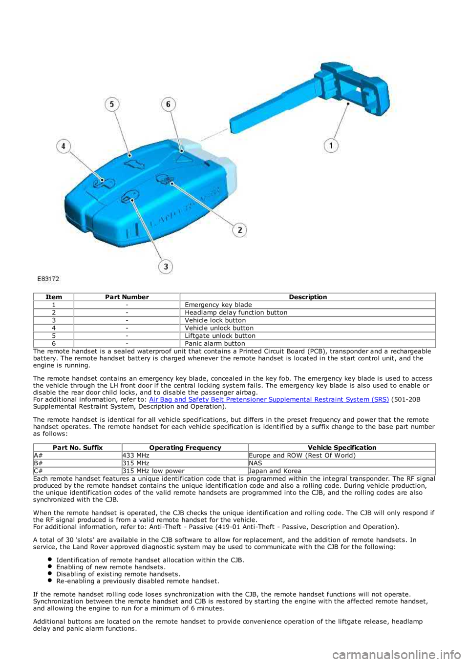
ItemPart NumberDescription1-Emergency key bl ade2-Headl amp delay funct ion but ton3-Vehicl e l ock button4-Vehicl e unlock button5-Li ftgate unlock butt on6-Panic alarm buttonThe remote hands et is a seal ed wat erproof uni t t hat contains a Printed Ci rcuit Board (PCB), transponder and a rechargeablebattery. The remote hands et batt ery i s charged whenever the remote hands et is located i n the s tart cont rol unit , and t heengi ne is running.
The remote hands et cont ai ns an emergency key blade, conceal ed in t he key fob. The emergency key bl ade i s us ed to acces sthe vehicle through the LH front door i f t he central locki ng syst em fai ls. The emergency key bl ade is als o us ed t o enable ordis able t he rear door chil d locks , and t o dis able t he pas senger ai rbag.For addit ional informat ion, refer t o: Ai r Bag and Safet y Belt Pretens ioner Supplement al Rest raint Sys tem (SRS) (501-20BSupplemental Res traint Sys tem, Des cription and Operat ion).
The remote hands et is identi cal for all vehicl e s peci ficat ions, but di ffers in t he pres et frequency and power that the remotehandset operates. The remot e handset for each vehicle specificat ion is ident ifi ed by a s uffix change to the base part numberas follows:
Part No. SuffixOperating FrequencyVehicle SpecificationA#433 MHzEurope and ROW (Rest Of W orld)B#315 MHzNASC#315 MHz low powerJapan and KoreaEach remot e handset features a uni que ident ifi cation code that is programmed within t he integral trans ponder. The RF si gnalproduced by t he remot e handset contains t he uni que ident ifi cation code and also a rolli ng code. Duri ng vehicl e product ion,the unique identification codes of the valid remot e handsets are programmed int o the CJB, and the roll ing codes are al sosynchronized wi th the CJB.
W hen the remote handset is operat ed, t he CJB checks t he unique i dent ificat ion and rol ling code. The CJB will only respond ifthe RF si gnal produced is from a val id remote hands et for the vehicle.For addit ional informat ion, refer t o: Anti -Theft - Pas si ve (419-01 Anti -Theft - Pas si ve, Des cript ion and Operati on).
A tot al of 30 'sl ots ' are availabl e in the CJB s oftware to al low for repl acement, and the addi tion of remote hands et s. Inservi ce, t he Land Rover approved di agnost ic system may be us ed to communicat e wit h the CJB for the followi ng:
Identi ficati on of remote handset all ocat ion wit hin t he CJB.Enabli ng of new remot e handsets .Disabl ing of exist ing remote handsets .Re-enabling a previ ously disabled remot e handset.
If the remote hands et rolling code l os es synchronizati on with t he CJB, t he remot e handset funct ions will not operate.Synchronizati on between the remote hands et and CJB is rest ored by s tart ing t he engine wit h t he affect ed remot e handset,and all owing the engine to run for a minimum of 6 mi nutes.
Addi tional buttons are located on the remote hands et to provide convenience operati on of t he li ftgat e rel ease, headlampdelay and panic al arm functions .
Page 2366 of 3229
Publi s hed: 11-May-2011
Roof Opening Panel -
Torque SpecificationsDescriptionNmlb-ft
Roof opening panel mot or Torx s crews54
Roof opening panel ali gnment Torx screws32Roof opening panel bolt s32
Roof opening panel mot or t ether44