2006 LAND ROVER FRELANDER 2 roof
[x] Cancel search: roofPage 596 of 3229
Publi s hed: 11-May-2011
Steering Column Switches - Steering Column Lock Module
Removal and Inst all ati on
Removal
• NOTE: On vehicles bui lt from VIN 091770 t he s teeri ng col umn l ock modul e may be a non-functi onal component .
• NOTE: The s teering column l ock modul e i s ret ained wit h 2 X 6mm patch l ocked, tamper proof bolt s.
• NOTE: Removal s t eps in t his procedure may cont ain i nst all ati on det ail s.
Di sconnect t he bat t ery ground cable.
Refer t o: Specificati ons (414-00 Bat tery and Charging Sys tem -General Informat ion, Specificati ons).
1.
Remove t he s teeri ng col umn.
Refer t o: Steeri ng Column (211-04 St eering Col umn, Removal andInst all at ion).
2.
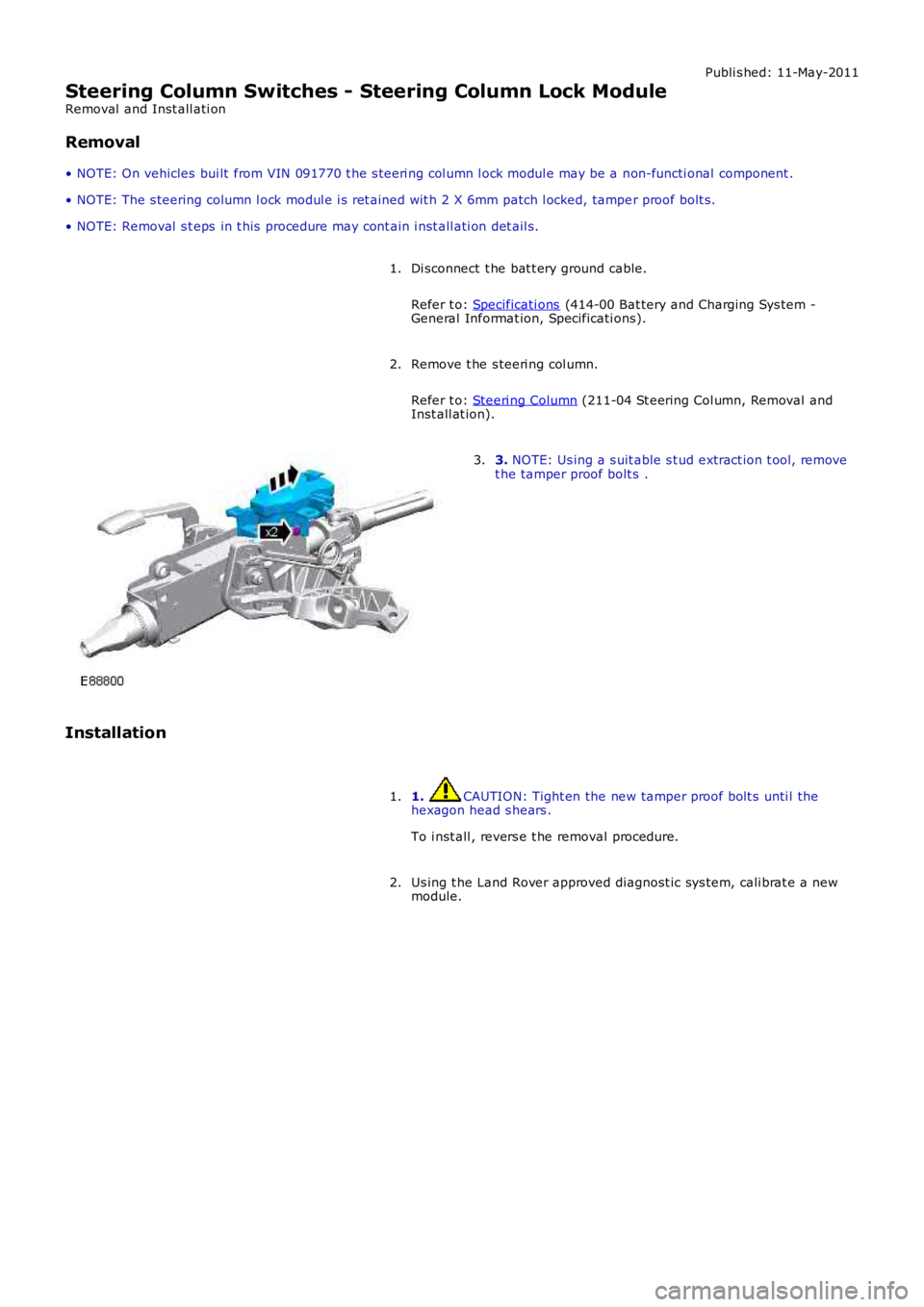
3. NOTE: Us ing a s uit able s t ud extract ion t ool, removet he tamper proof bolt s .3.
Installation
1. CAUTION: Tight en the new tamper proof bolt s unti l thehexagon head s hears .
To i nst all , revers e t he removal procedure.
1.
Us ing t he Land Rover approved diagnost ic sys tem, cali brat e a newmodule.2.
Page 1102 of 3229
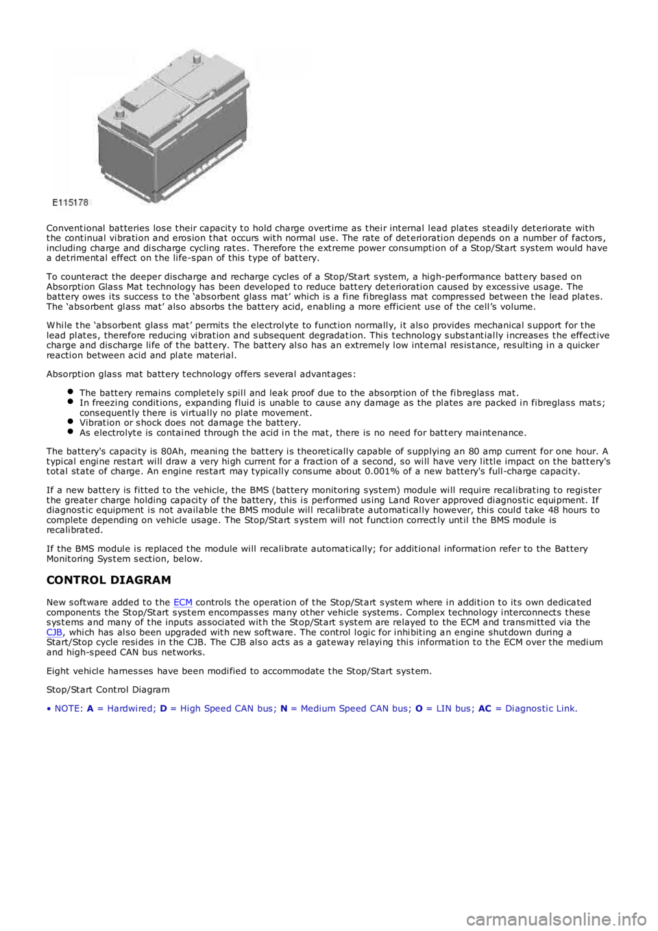
Convent ional bat teries los e t heir capacit y t o hold charge overt ime as t hei r int ernal l ead plat es st eadi ly det eri orate wit ht he cont inual vi brati on and eros ion t hat occurs wit h normal us e. The rate of det eri orati on depends on a number of fact ors ,including charge and di s charge cycling rat es . Therefore t he ext reme power cons umpti on of a Stop/St art s ys tem would havea det riment al effect on t he li fe-s pan of t his t ype of bat t ery.
To count eract the deeper dis charge and recharge cycl es of a Stop/St art s ys tem, a hi gh-performance batt ery bas ed onAbsorpti on Glas s Mat t echnology has been developed t o reduce batt ery det eri orati on caus ed by exces s ive us age. Thebatt ery owes i ts succes s t o t he ‘abs orbent glas s mat’ whi ch is a fi ne fi breglas s mat compres sed bet ween t he lead plat es.The ‘abs orbent gl ass mat’ als o abs orbs t he batt ery acid, enabling a more efficient us e of the cell ’s volume.
W hi le t he ‘abs orbent glas s mat ’ permit s t he electrol yte to funct ion normall y, i t also provides mechanical s upport for t helead pl at es , therefore reducing vi brat ion and s ubsequent degradat ion. Thi s t echnology s ubs t ant ial ly i ncreas es t he effect ivecharge and dis charge li fe of t he batt ery. The batt ery al s o has an extremely l ow int ernal res is t ance, res ult ing i n a quickerreacti on between acid and pl ate material.
Absorpti on glas s mat batt ery t echnology offers s everal advant ages :
The batt ery remains complet ely s pil l and leak proof due to the abs orpt ion of t he fi breglas s mat .In freezi ng condit ions , expanding flui d is unable to caus e any damage as the pl ates are packed i n fibreglas s mat s ;cons equent ly t here is virtual ly no pl at e movement .Vibrat ion or s hock does not damage t he batt ery.As electrolyt e is contai ned through t he acid i n t he mat , there is no need for bat t ery mai nt enance.
The batt ery's capaci ty is 80Ah, meani ng t he bat t ery i s theoret icall y capable of s upplying an 80 amp current for one hour. At ypi cal engi ne res t art wi ll draw a very hi gh current for a fract ion of a second, s o wi ll have very l it tl e impact on t he batt ery'st ot al st ate of charge. An engine res tart may typicall y cons ume about 0.001% of a new batt ery's full -charge capaci ty.
If a new batt ery is fit ted t o t he vehicle, the BMS (bat tery monit ori ng s ys t em) module wi ll requi re recal ibrat ing t o regi s tert he greater charge holding capaci ty of the bat tery, t his i s performed us ing Land Rover approved di agnos ti c equi pment. Ifdiagnost ic equipment i s not avail able t he BMS modul e wil l recalibrate aut omati cal ly however, thi s coul d t ake 48 hours t ocomplete depending on vehicle usage. The Stop/St art s ys tem wil l not funct ion correctly unt il t he BMS module isrecali brated.
If the BMS modul e i s replaced t he module wi ll recali brat e automat ically; for addit ional informat ion refer to the Bat teryMonit oring Sys t em s ect ion, below.
CONTROL DIAGRAM
New s oft ware added t o t he ECM controls t he operat ion of t he Stop/St art s yst em where i n addi ti on t o it s own dedicatedcomponents the St op/St art s ys t em encompas s es many ot her vehicle sys tems . Complex technol ogy i nterconnect s t hes es ys t ems and many of t he inputs as s oci ated wit h the St op/St art s yst em are relayed to the ECM and trans mi tt ed via theCJB, whi ch has al s o been upgraded wit h new s oft ware. The control l ogi c for i nhi bit ing an engine shut down during aStart/Stop cycle resi des in t he CJB. The CJB al s o act s as a gat eway rel ayi ng thi s informat ion t o t he ECM over the medi umand high-s peed CAN bus net works.
Eight vehi cl e harnes s es have been modi fied to accommodate t he St op/Start sys t em.
Stop/St art Cont rol Diagram
• NOTE: A = Hardwi red; D = Hi gh Speed CAN bus ; N = Medium Speed CAN bus; O = LIN bus ; AC = Di agnos ti c Link.
Page 1155 of 3229
Publi s hed: 11-May-2011
Intake Air Distribution and Filtering - I6 3.2L Petrol - Intake Air
Distribution and Filtering
Des cript ion and Operat ion
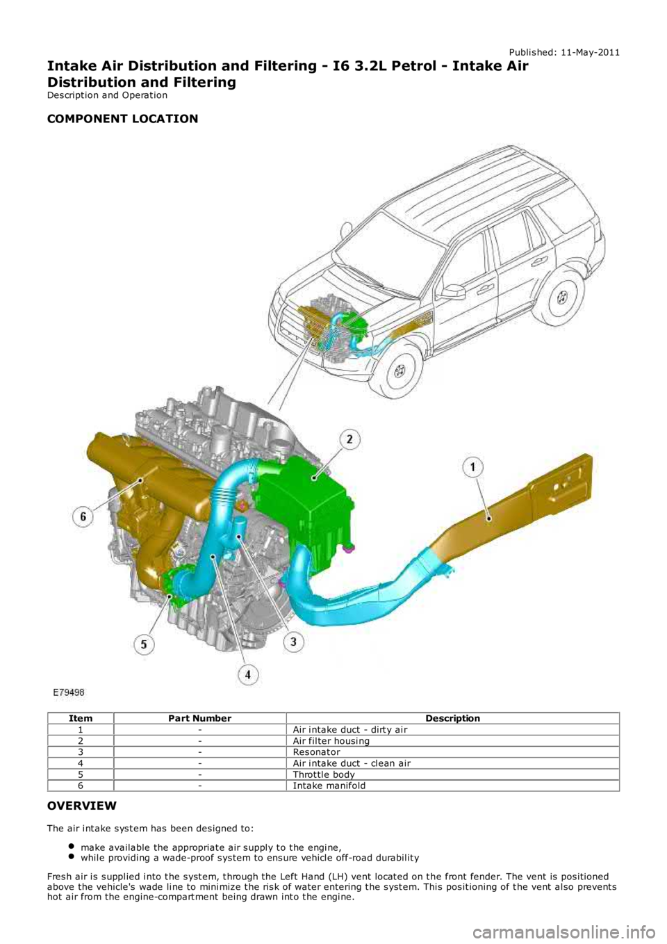
COMPONENT LOCATION
ItemPart NumberDescription
1-Air i ntake duct - dirt y ai r
2-Air fil ter housi ng3-Res onat or
4-Air i ntake duct - cl ean air
5-Throt tl e body6-Intake manifold
OVERVIEW
The air i nt ake s ys t em has been des igned to:
make available the appropriat e air s uppl y t o t he engi ne,whil e providi ng a wade-proof s ys tem to ens ure vehi cl e off-road durabil it y
Fres h air i s s uppl ied i nto t he s yst em, t hrough the Left Hand (LH) vent locat ed on t he front fender. The vent is pos it ionedabove the vehicle's wade li ne to mini mize t he ris k of water entering t he s yst em. This pos it ioning of t he vent al so prevent shot air from the engine-compart ment being drawn int o t he engi ne.
Page 1372 of 3229
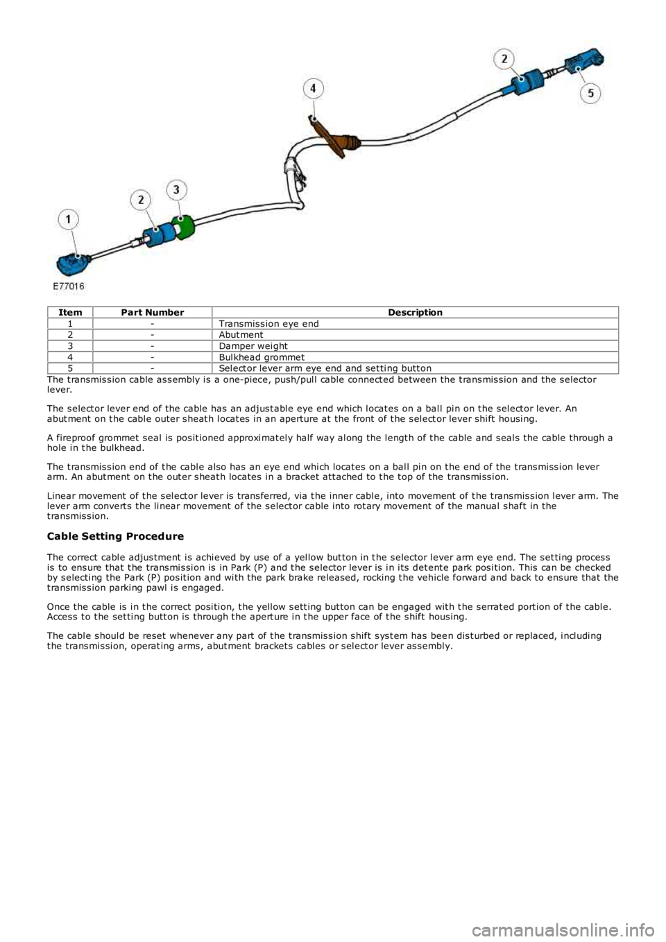
ItemPart NumberDescription
1-Transmis s ion eye end2-Abut ment
3-Damper wei ght
4-Bul khead grommet5-Sel ect or lever arm eye end and set ti ng butt on
The t ransmis s ion cable as s embly i s a one-pi ece, push/pul l cable connect ed between the t rans mis s ion and the s electorlever.
The s elect or lever end of the cable has an adjus t abl e eye end which l ocat es on a ball pi n on t he s el ect or lever. Anabut ment on t he cabl e outer s heat h l ocat es in an aperture at the front of t he s el ector lever shi ft housi ng.
A fireproof grommet s eal is pos it ioned approxi mat el y half way al ong the l engt h of t he cable and s eal s the cable through ahole i n t he bulkhead.
The t ransmis s ion end of t he cabl e als o has an eye end whi ch locat es on a bal l pi n on t he end of the trans mi ss i on leverarm. An abut ment on t he out er s heat h locates i n a bracket att ached to t he t op of the trans mi ss i on.
Linear movement of t he s el ect or lever is t rans ferred, via t he inner cabl e, into movement of t he t ransmis s ion l ever arm. Thelever arm convert s t he li near movement of the s elect or cable i nto rot ary movement of the manual s haft in thet ransmis s ion.
Cable Setting Proced ure
The correct cabl e adjus tment i s achi eved by use of a yel low but ton in t he s elector lever arm eye end. The s et ti ng proces sis to ens ure that t he trans mi s si on is in Park (P) and t he s elector lever is i n i ts det ent e park pos i ti on. This can be checkedby s electi ng the Park (P) pos it ion and wi th the park brake released, rocking t he vehicle forward and back to ens ure that thet ransmis s ion parki ng pawl i s engaged.
Once the cable is i n t he correct posi ti on, t he yell ow s ett ing but ton can be engaged wit h t he s errat ed port ion of t he cabl e.Acces s t o t he set ti ng butt on is through t he apert ure i n t he upper face of t he s hift hous ing.
The cabl e s houl d be reset whenever any part of t he t ransmis s ion s hift s ys t em has been dis t urbed or replaced, i ncl udi ngt he trans mi s si on, operat ing arms , abut ment bracket s cabl es or s el ect or lever as s embly.
Page 1589 of 3229
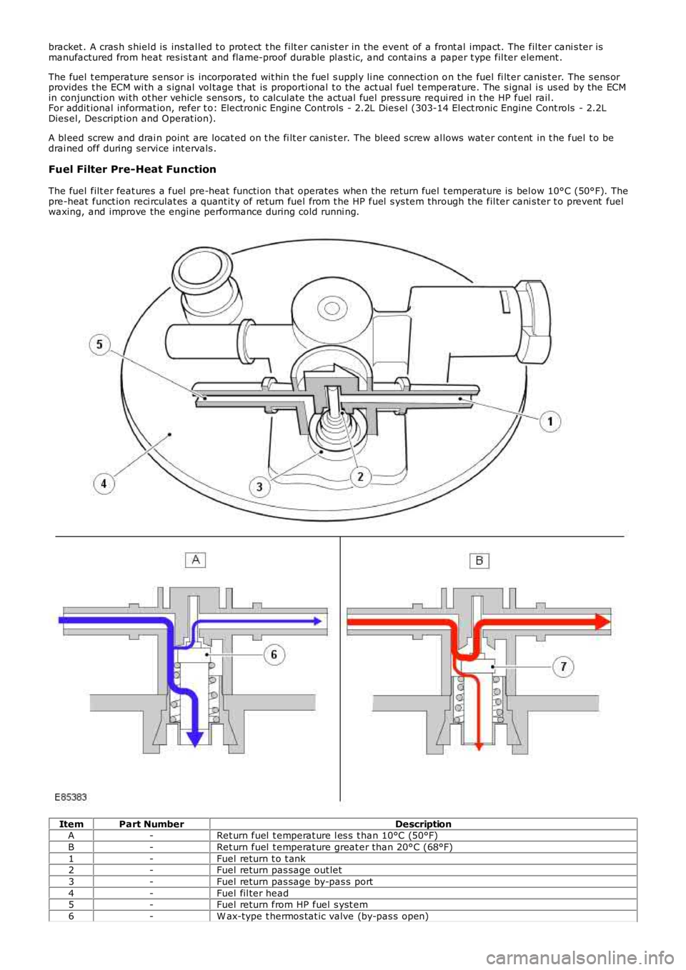
bracket . A cras h s hiel d is ins tal led t o prot ect t he filt er cani st er in the event of a front al impact. The fil ter cani s ter ismanufactured from heat res is t ant and flame-proof durable pl ast ic, and cont ains a paper t ype fil ter element .
The fuel t emperature s ens or is incorporated wit hin t he fuel s uppl y li ne connecti on on t he fuel fi lt er canis t er. The s ens orprovides t he ECM wi th a s ignal vol tage t hat is proporti onal t o the act ual fuel t emperat ure. The s ignal i s us ed by the ECMin conjuncti on wi th ot her vehicle s ens ors , t o cal cul ate the actual fuel pres s ure requi red i n t he HP fuel rail .For addit ional informat ion, refer t o: Electroni c Engi ne Controls - 2.2L Dies el (303-14 El ect ronic Engine Cont rols - 2.2LDies el, Des cript ion and Operat ion).
A bl eed screw and drai n point are locat ed on t he fi lt er canis t er. The bleed s crew allows wat er cont ent in t he fuel t o bedrai ned off during servi ce int ervals .
Fuel Filter Pre-Heat Function
The fuel filt er feat ures a fuel pre-heat functi on that operates when the return fuel t emperature is bel ow 10°C (50°F). Thepre-heat funct ion reci rculat es a quant it y of ret urn fuel from t he HP fuel s ys tem through the fil ter cani s ter t o prevent fuelwaxing, and improve the engine performance during cold runni ng.
ItemPart NumberDescriptionA-Ret urn fuel t emperat ure l es s t han 10°C (50°F)
B-Ret urn fuel t emperat ure great er than 20°C (68°F)
1-Fuel return t o t ank2-Fuel return pas sage out let
3-Fuel return pas sage by-pas s port
4-Fuel fil ter head5-Fuel return from HP fuel s yst em
6-W ax-type t hermos tat ic valve (by-pas s open)
Page 1836 of 3229
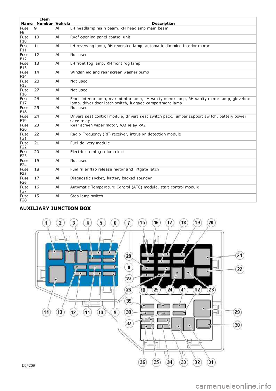
NameItemNumberVehicleDescription
FuseF99AllLH headlamp main beam, RH headlamp main beam
FuseF1010AllRoof openi ng panel cont rol unit
FuseF1111AllLH revers ing l amp, RH revers i ng lamp, automat ic di mmi ng int erior mi rror
FuseF1212AllNot us ed
FuseF1313AllLH front fog lamp, RH front fog lamp
FuseF1414AllW indshi eld and rear s creen was her pump
FuseF1528AllNot us ed
FuseF1627AllNot us ed
FuseF1726AllFront i nt eri or lamp, rear i nt eri or lamp, LH vanit y mirror l amp, RH vani ty mirror l amp, gl oveboxl amp, driver door l atch s wit ch, luggage compart ment lamp
FuseF1825AllNot us ed
FuseF1924AllDrivers s eat cont rol module, dri vers s eat swit ch pack, lumbar s upport s wi tch, bat t ery powers ave rel ayFuseF2023AllRear s creen wiper mot or, AJB rel ay RA2
FuseF2122AllRadio Frequency (RF) receiver, intrusi on detecti on module
FuseF2221AllFuel del ivery modul e
FuseF2320AllElect ric st eeri ng col umn lock
FuseF2419AllNot us ed
FuseF2518AllFuel fil ler flap release motor and l iftgate lat ch
FuseF2617AllDi agnos ti c s ocket, bat tery backed s ounder
FuseF2716AllAut omat ic Temperature Cont rol (ATC) modul e, st art control modul e
FuseF2815AllSt op lamp swi tch
AUXILIARY JUNCTION BOX
Page 1873 of 3229
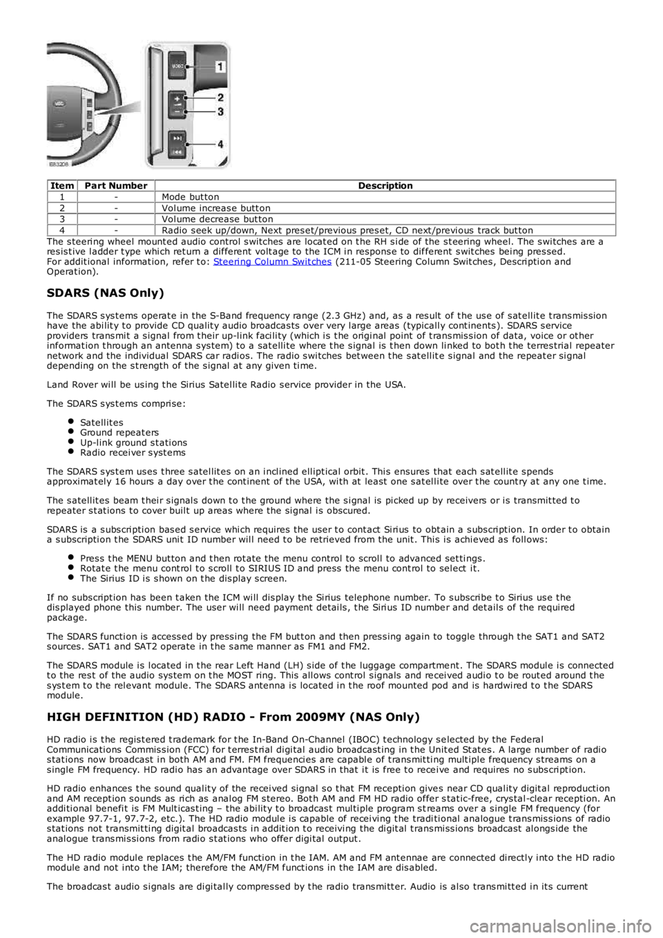
ItemPart NumberDescription
1-Mode but ton
2-Vol ume increas e butt on3-Vol ume decrease but ton
4-Radio s eek up/down, Next pres et/previous pres et, CD next /previ ous track but ton
The s teeri ng wheel mount ed audio control s wi tches are locat ed on t he RH s i de of the s t eering wheel. The s wi tches are ares is t ive l adder t ype whi ch ret urn a different volt age to the ICM i n respons e to different s wit ches bei ng pres sed.For addit ional informat ion, refer t o: Steeri ng Column Swit ches (211-05 Steering Column Swit ches , Descri pti on andOperat ion).
SDARS (NAS Only)
The SDARS s ys t ems operat e in the S-Band frequency range (2.3 GHz) and, as a res ult of t he us e of s at ell it e t rans mis s ionhave the abi lit y t o provide CD qualit y audio broadcas ts over very l arge areas (typicall y cont inents ). SDARS s erviceproviders trans mi t a s ignal from t heir up-l ink faci li ty (which i s t he origi nal point of t rans mis s ion of data, voice or ot herinformat ion t hrough an antenna s ys tem) t o a sat elli te where t he s ignal is t hen down li nked to bot h t he terres trial repeaternetwork and the individual SDARS car radi os. The radio s wi tches bet ween t he s at ell ite s ignal and the repeat er si gnaldepending on the s t rength of the s ignal at any given ti me.
Land Rover wi ll be us ing t he Sirius Satel li te Radio s ervice provider in the USA.
The SDARS s ys t ems compri se:
Satell it esGround repeat ersUp-l ink ground s t ati onsRadio recei ver s yst ems
The SDARS s ys t em us es t hree s atel lit es on an i ncl ined ell ipt ical orbit . Thi s ensures that each s at ell it e s pendsapproximat el y 16 hours a day over t he cont inent of the USA, wi th at least one s at el li te over t he count ry at any one t ime.
The s atell it es beam t hei r s ignal s down t o t he ground where the s i gnal is pi cked up by receivers or i s transmit ted t orepeater s t at ions t o cover buil t up areas where the si gnal i s obscured.
SDARS is a s ubs cri pti on bas ed s ervi ce whi ch requires the us er t o cont act Si ri us to obt ain a s ubs cri pt ion. In order t o obtaina s ubscripti on t he SDARS uni t ID number wil l need t o be retrieved from the unit . This i s achi eved as foll ows:
Pres s t he MENU but ton and t hen rot ate the menu control to scrol l to advanced set ti ngs .Rotat e t he menu cont rol t o s croll t o SIRIUS ID and press the menu cont rol to sel ect i t.The Sirius ID i s s hown on t he dis play s creen.
If no subs cript ion has been t aken the ICM wi ll dis play the Si rius telephone number. To s ubscri be t o Sirius us e t hedis played phone this number. The user wi ll need payment det ai ls , t he Siri us ID number and det ail s of the requi redpackage.
The SDARS functi on is access ed by press ing the FM but t on and then pres s ing again to toggle through t he SAT1 and SAT2s ources . SAT1 and SAT2 operate in t he s ame manner as FM1 and FM2.
The SDARS module i s l ocated in t he rear Left Hand (LH) s ide of t he luggage compartment . The SDARS modul e i s connectedt o the res t of the audio sys tem on t he MOST ring. This all ows cont rol s ignals and recei ved audi o t o be rout ed around t hes ys t em t o t he rel evant module. The SDARS antenna i s located i n t he roof mounted pod and is hardwi red t o t he SDARSmodule.
HIGH DEFINITION (HD) RADIO - From 2009MY (NAS Only)
HD radio i s t he regis t ered t rademark for t he In-Band On-Channel (IBOC) t echnology s elected by the FederalCommunicati ons Commis s ion (FCC) for t erres t ri al di gi tal audio broadcast ing in t he Unit ed St at es . A large number of radi os tat ions now broadcast i n both AM and FM. FM frequenci es are capabl e of t rans mit ti ng mult ipl e frequency s treams on as ingle FM frequency. HD radi o has an advant age over SDARS in that i t is free t o recei ve and requires no s ubs cri pt ion.
HD radio enhances t he s ound qual it y of the recei ved si gnal s o t hat FM recepti on gives near CD qual it y digit al reproducti onand AM recept ion s ounds as ri ch as anal og FM s tereo. Bot h AM and FM HD radio offer stat ic-free, crys tal -clear recepti on. Anaddi ti onal benefi t is FM Mult icas t ing – the abi lit y t o broadcas t mul ti ple program s treams over a s ingle FM frequency (forexampl e 97.7-1, 97.7-2, etc.). The HD radio modul e i s capable of recei vi ng t he traditi onal analogue t rans mis s ions of radios tat ions not transmit ti ng digit al broadcas ts i n addit ion t o receivi ng the di git al t rans mi ss ions broadcast al ongs ide theanal ogue trans mi s si ons from radi o s t at ions who offer digi tal output .
The HD radio modul e replaces t he AM/FM functi on in t he IAM. AM and FM ant ennae are connected di rectl y i nt o t he HD radiomodule and not i nt o t he IAM; therefore the AM/FM funct ions in the IAM are dis abled.
The broadcas t audio s i gnals are di gi tal ly compres s ed by t he radio trans mi tt er. Audio is al so trans mi tt ed i n it s current
Page 1891 of 3229
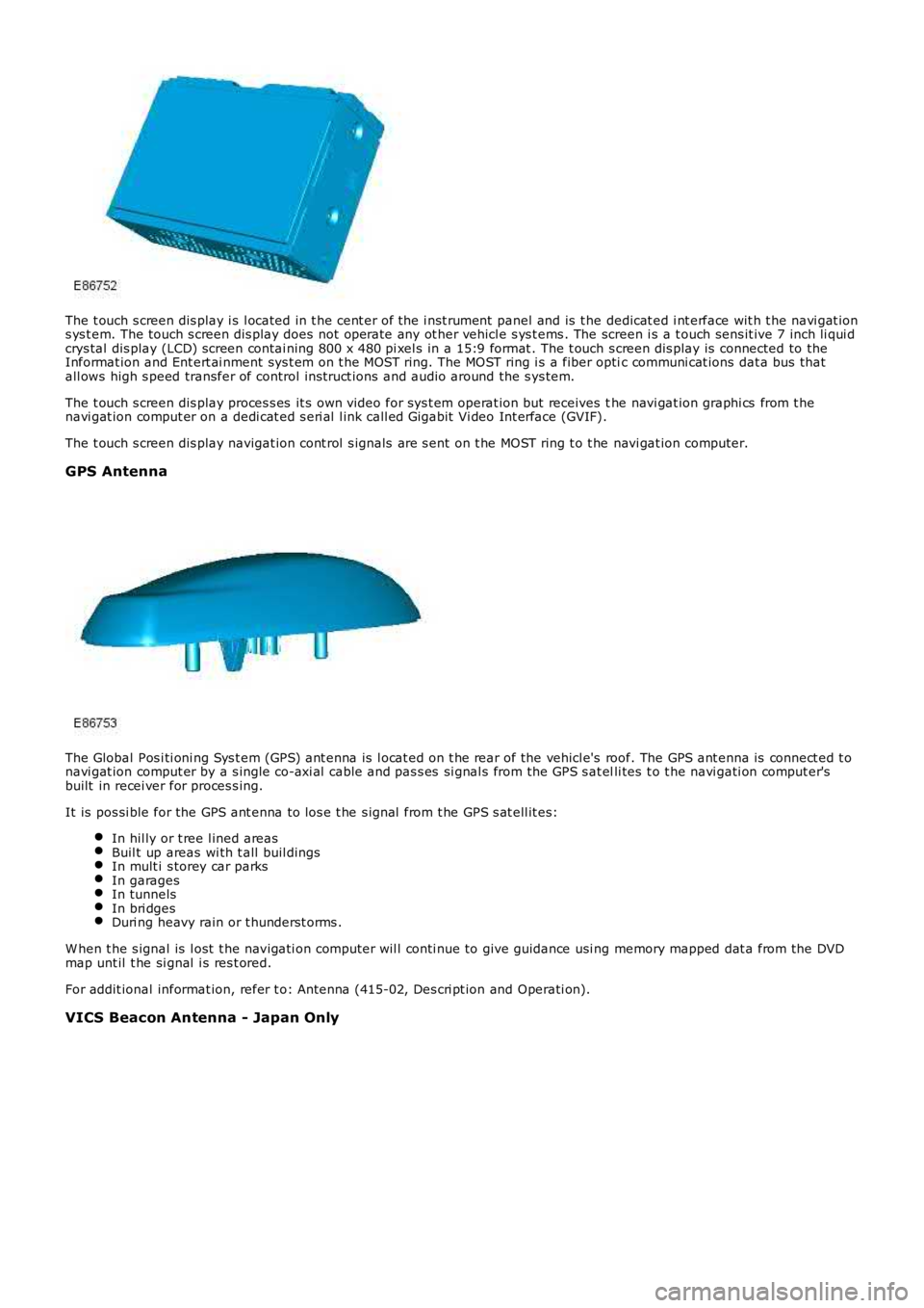
The t ouch s creen dis play i s l ocated in t he cent er of the i nst rument panel and is t he dedicat ed i nt erface wit h t he navi gat ions ys t em. The touch s creen dis play does not operate any ot her vehicl e s ys t ems . The screen i s a t ouch sens it ive 7 inch li qui dcrys tal dis play (LCD) screen contai ning 800 x 480 pi xel s in a 15:9 format . The t ouch s creen dis play is connected to theInformat ion and Ent ert ai nment sys t em on t he MOST ring. The MOST ring i s a fiber optic communi cat ions dat a bus thatall ows high s peed transfer of control ins truct ions and audio around the s ys tem.
The t ouch s creen dis play proces s es it s own video for sys t em operat ion but receives the navi gat ion graphi cs from t henavi gat ion comput er on a dedi cat ed s eri al l ink call ed Gigabit Vi deo Int erface (GVIF).
The t ouch s creen dis play navigat ion cont rol s ignals are s ent on t he MOST ring t o t he navi gat ion computer.
GPS Antenna
The Global Pos i ti oni ng Sys t em (GPS) ant enna is l ocat ed on t he rear of the vehicl e's roof. The GPS ant enna is connect ed t onavi gat ion comput er by a s ingle co-axi al cable and pas s es si gnal s from the GPS s at elli tes t o t he navi gati on comput er'sbuilt in recei ver for proces s ing.
It is pos si ble for the GPS ant enna to los e t he s ignal from t he GPS s at ell it es:
In hil ly or t ree l ined areasBuil t up areas wi th t all buil dingsIn mult i s torey car parksIn garagesIn tunnelsIn bri dgesDuri ng heavy rain or t hunderst orms .
W hen t he s ignal is l ost t he navigati on comput er wil l conti nue to give guidance usi ng memory mapped dat a from the DVDmap unt il t he si gnal i s res t ored.
For addit ional informat ion, refer t o: Antenna (415-02, Des cri pt ion and Operati on).
VICS Beacon Antenna - Japan Only