2006 LAND ROVER FRELANDER 2 wiper fluid
[x] Cancel search: wiper fluidPage 200 of 3229
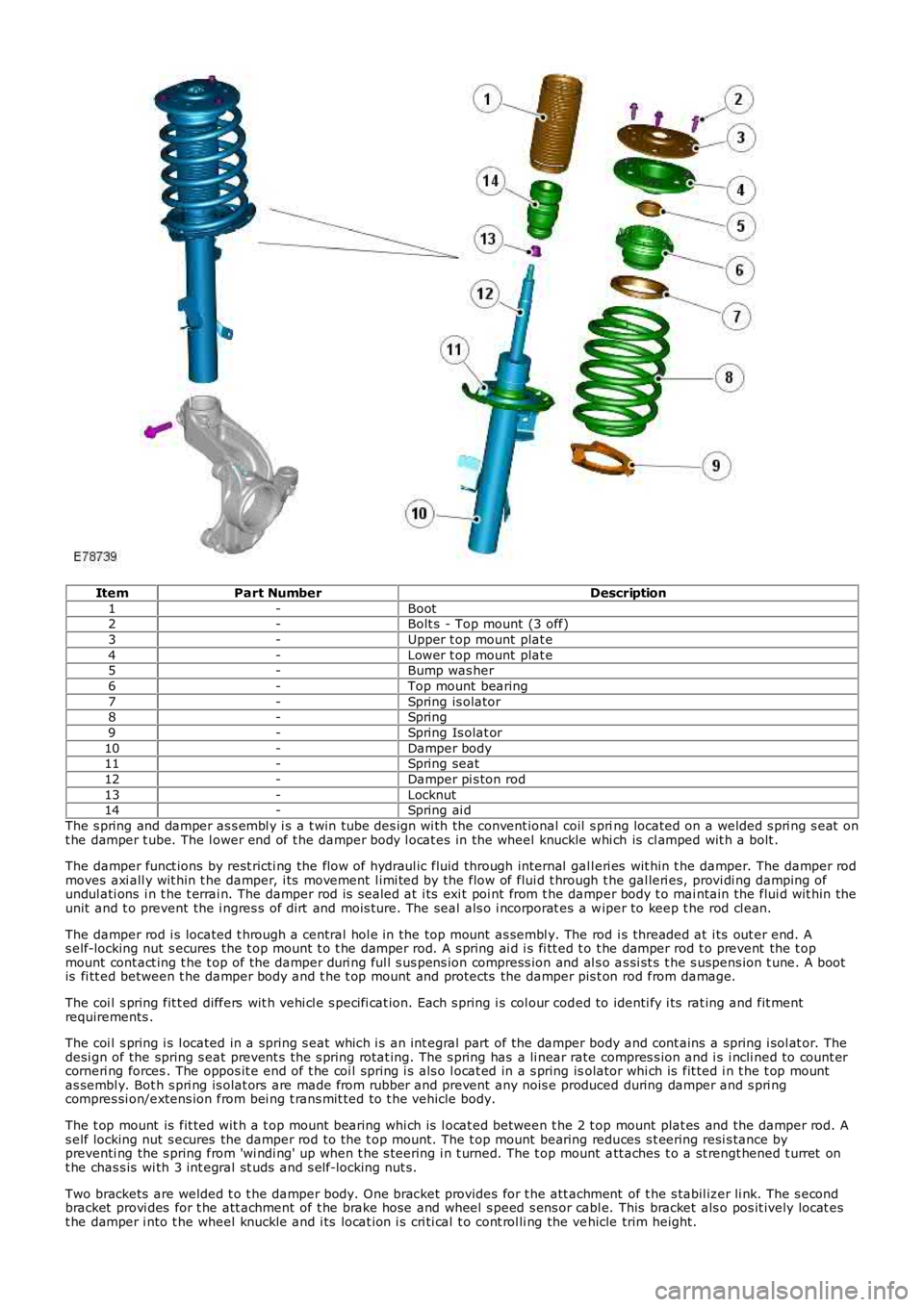
ItemPart NumberDescription
1-Boot2-Bolt s - Top mount (3 off)
3-Upper t op mount plat e
4-Lower t op mount plat e5-Bump was her
6-Top mount bearing
7-Spring is olator8-Spring
9-Spring Is olat or
10-Damper body11-Spring seat
12-Damper pi s ton rod
13-Locknut14-Spring ai d
The s pring and damper as s embl y i s a t win tube des ign wi th the convent ional coil s pring located on a welded s pri ng s eat ont he damper t ube. The l ower end of t he damper body l ocat es in the wheel knuckle whi ch is cl amped wit h a bolt .
The damper funct ions by rest ricti ng the flow of hydraul ic fluid through internal gall eri es wit hin t he damper. The damper rodmoves axi all y wit hin t he damper, i ts movement l imi ted by the flow of flui d t hrough the gal leri es, provi di ng damping ofundul ati ons i n t he t errai n. The damper rod is s ealed at i ts exi t poi nt from t he damper body t o mai ntain the flui d wit hin theunit and t o prevent the i ngres s of dirt and mois ture. The seal als o i ncorporat es a wiper to keep t he rod cl ean.
The damper rod i s located t hrough a central hol e in the top mount as sembl y. The rod i s threaded at i ts out er end. As elf-locking nut s ecures the t op mount t o t he damper rod. A s pring ai d i s fi tt ed t o t he damper rod t o prevent the t opmount cont act ing t he t op of the damper duri ng ful l s us pens ion compress ion and al s o as si st s t he s uspens ion t une. A bootis fi tt ed between t he damper body and t he t op mount and protects the damper pis t on rod from damage.
The coi l s pring fit t ed differs wit h vehi cl e s peci fi cat ion. Each s pring i s col our coded to identi fy i ts rat ing and fit mentrequirements .
The coi l s pring i s l ocated in a spring s eat which i s an int egral part of the damper body and cont ains a spring i sol at or. Thedesi gn of the spring s eat prevent s t he s pring rotat ing. The s pring has a li near rate compres s ion and i s i ncli ned to count ercorneri ng forces . The oppos it e end of t he coi l spring i s als o l ocat ed in a s pring isolator whi ch is fit ted i n t he t op mountas sembl y. Bot h s pri ng is olat ors are made from rubber and prevent any nois e produced during damper and s pri ngcompres si on/extens ion from bei ng t rans mit ted to t he vehicle body.
The t op mount is fit ted wit h a t op mount bearing whi ch is l ocat ed between t he 2 t op mount plat es and the damper rod. As elf locking nut s ecures the damper rod to the t op mount. The t op mount bearing reduces s t eering resi s tance bypreventi ng the s pring from 'wi ndi ng' up when t he s teering i n t urned. The t op mount att aches t o a st rengt hened t urret ont he chas s is wi th 3 int egral st uds and s elf-locking nut s.
Two brackets are welded t o t he damper body. One bracket provides for t he att achment of t he s tabil izer li nk. The s econdbracket provi des for t he att achment of t he brake hose and wheel s peed s ens or cabl e. This bracket als o pos it ively locat est he damper i nto t he wheel knuckle and i ts locat ion i s cri ti cal t o cont rol li ng the vehicle trim height.
Page 232 of 3229
SPRING AND DAMPER
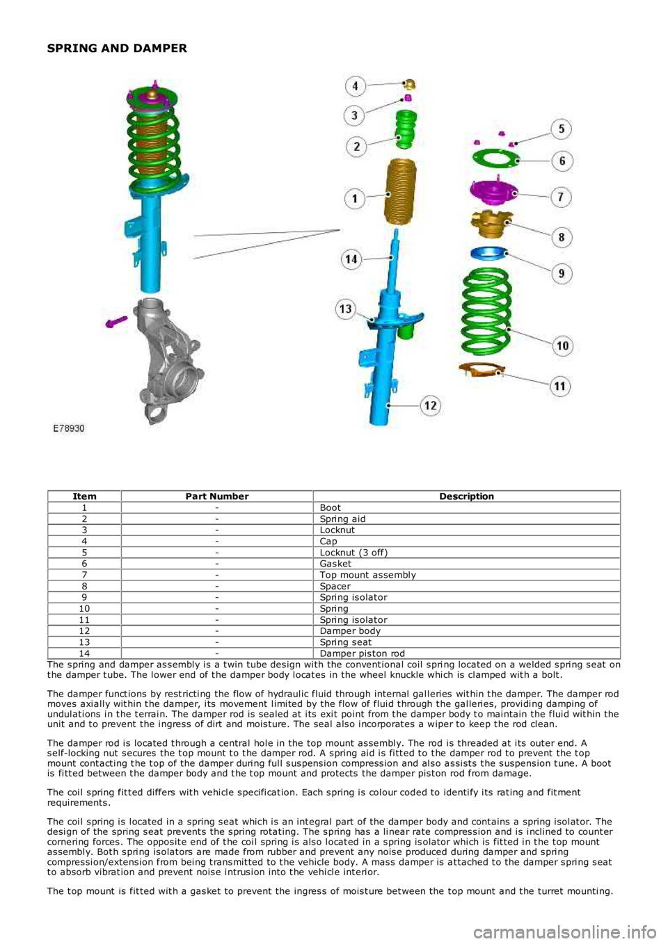
ItemPart NumberDescription
1-Boot
2-Spri ng aid3-Locknut
4-Cap
5-Locknut (3 off)6-Gas ket
7-Top mount as sembl y
8-Spacer9-Spri ng is olat or
10-Spri ng
11-Spri ng is olat or12-Damper body
13-Spri ng s eat
14-Damper pis t on rodThe s pring and damper as s embl y i s a t win tube des ign wi th the convent ional coil s pring located on a welded s pri ng s eat ont he damper t ube. The l ower end of t he damper body l ocat es in the wheel knuckle whi ch is cl amped wit h a bolt .
The damper funct ions by rest ricti ng the flow of hydraul ic fluid through internal gall eri es wit hin t he damper. The damper rodmoves axi all y wit hin t he damper, i ts movement l imi ted by the flow of flui d t hrough the gal leri es, provi di ng damping ofundul ati ons i n t he t errai n. The damper rod is s ealed at i ts exi t poi nt from t he damper body t o mai ntain the flui d wit hin theunit and t o prevent the i ngres s of dirt and mois ture. The seal als o i ncorporat es a wiper to keep t he rod cl ean.
The damper rod i s located t hrough a central hol e in the top mount as sembl y. The rod i s threaded at i ts out er end. As elf-locking nut s ecures the t op mount t o t he damper rod. A s pring ai d i s fi tt ed t o t he damper rod t o prevent the t opmount cont act ing t he t op of the damper duri ng ful l s us pens ion compress ion and al s o as si st s t he s uspens ion t une. A bootis fi tt ed between t he damper body and t he t op mount and protects the damper pis t on rod from damage.
The coi l s pring fit t ed differs wit h vehi cl e s peci fi cat ion. Each s pring i s col our coded to identi fy i ts rat ing and fit mentrequirements .
The coi l s pring i s l ocated in a spring s eat which i s an int egral part of the damper body and cont ains a spring i sol at or. Thedesi gn of the spring s eat prevent s t he s pring rotat ing. The s pring has a li near rate compres s ion and i s i ncli ned to count ercorneri ng forces . The oppos it e end of t he coi l spring i s als o l ocat ed in a s pring isolator whi ch is fit ted i n t he t op mountas sembl y. Bot h s pri ng is olat ors are made from rubber and prevent any nois e produced during damper and s pri ngcompres si on/extens ion from bei ng t rans mit ted to t he vehicle body. A mas s damper is at tached t o the damper s pri ng s eatt o absorb vibrat ion and prevent nois e i ntrus i on int o t he vehi cl e int eri or.
The t op mount is fit ted wit h a gas ket t o prevent the ingres s of mois t ure bet ween the t op mount and t he turret mounti ng.
Page 489 of 3229
Publi s hed: 11-May-2011
Power Brake Actuation - Brake Booster
Removal and Inst all ati on
Removal
• CAUTIO NS:
Extreme cleanli nes s mus t be exercis ed when handli ng thes e component s.
If brake fluid is s pil t on the pai ntwork, t he affect ed area must be immedi ately washed down wi th col d wat er.
All vehicles
1. W ARNING: Make sure t o s upport the vehicle wit h axles tands .
Rais e and s upport t he vehi cl e.
1.
Di sconnect t he bat t ery ground cable.
Refer t o: Specificati ons (414-00 Bat tery and Charging Sys tem -General Informat ion, Specificati ons).
2.
Remove t he winds hield wiper motor and l inkage.
Refer t o: W i nds hield W i per Mot or (501-16 W ipers and W as hers ,Removal and Ins tall ati on).
3.
Remove t he dri ver l ower ai r bag modul e.
Refer t o: Dri ver Lower Air Bag Module (501-20B SupplementalRes traint Sys t em, Removal and Inst all at ion).
4.
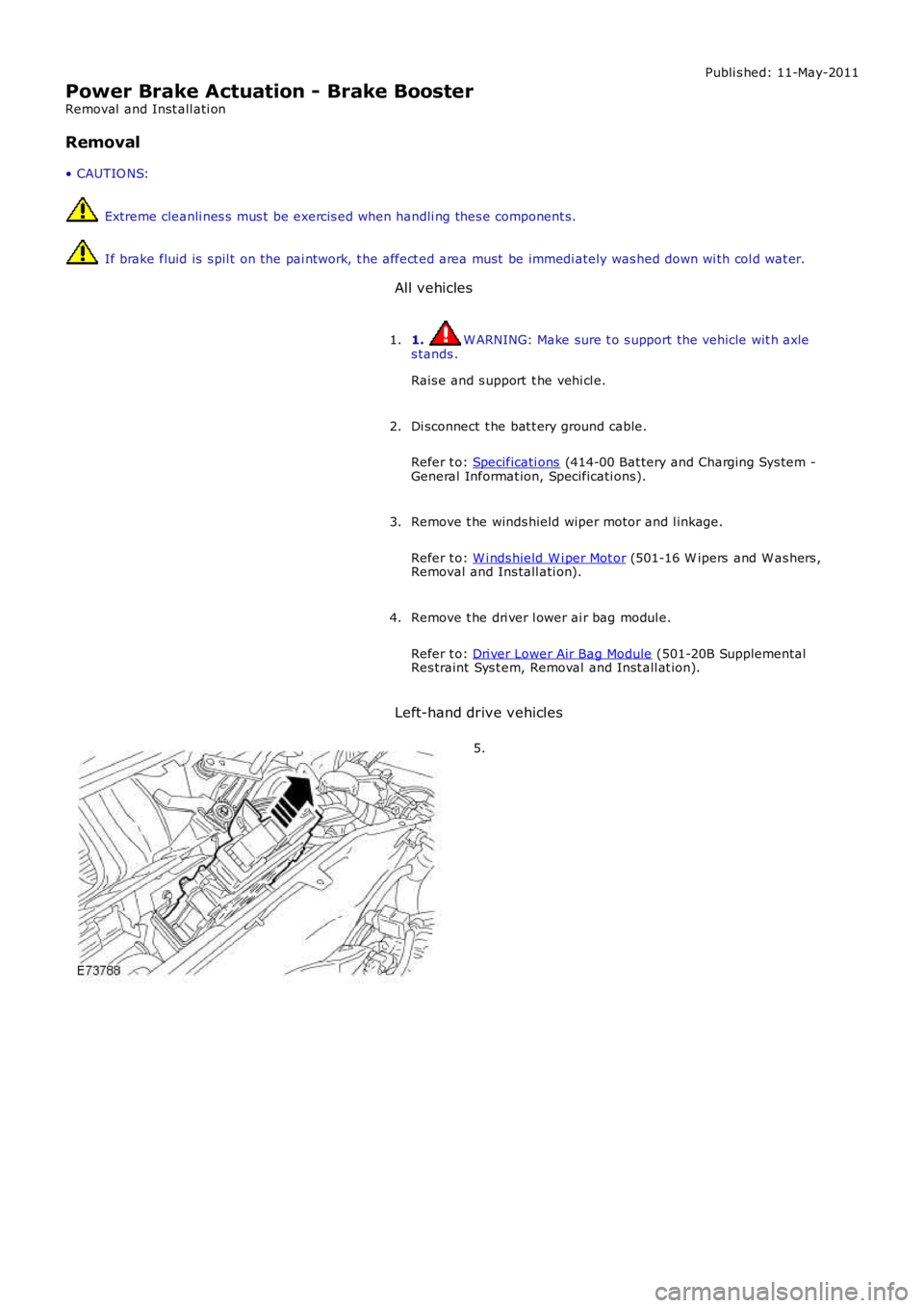
Left-hand drive vehicles
5.
Page 492 of 3229

Installation
All vehicles
1. CAUTION: Make s ure that the mati ng faces are cl ean and
free of foreign mat eri al.
Inst all t he brake mas ter cyli nder.
T orque: 26 Nm 1.
2. CAUTION: Make s ure that the mati ng faces are cl ean and
free of foreign mat eri al.
Inst all t he brake boost er.
T orque: 22 Nm 2.
3. CAUTION: Make s ure that the mati ng faces are cl ean and
free of foreign mat eri al.
Inst all t he brake fluid tubes.
T orque: 15 Nm 3.
Vehicles with manual transmission 4. CAUTION: Make s ure that the mati ng faces are cl ean and
free of foreign mat eri al.
Connect t he clutch flui d li ne.
4.
All vehicles Connect t he brake boost er vacuum l ine.
5.
Connect t he low brake fl uid warning i ndi cat or swit ch el ect ri cal
connector.
6.
Left-hand drive vehicles Inst all t he ECM bracket.
T orque: 10 Nm 7.
Inst all t he ECM.
8.
All vehicles Inst all t he dri ver l ower ai r bag modul e.
Refer t o: Dri ver Lower Air Bag Module (501-20B Supplemental
Res traint Sys t em, Removal and Inst all at ion).
9.
Inst all t he winds hield wiper motor and l inkage.
Refer t o: W i nds hield W i per Mot or (501-16 W ipers and W as hers ,
Removal and Ins tall ati on).
10.
Connect t he batt ery ground cable.
11.
Page 502 of 3229
Publi s hed: 11-May-2011
Anti-Lock Control - Anti-Lock Brake System (ABS) Module
Removal and Inst all ati on
Removal
• CAUTIO NS:
Extreme cleanli nes s mus t be exercis ed when handli ng thes e component s.
If brake fluid is s pil t on the pai ntwork, t he affect ed area must be immedi ately washed down wi th col d wat er.
All vehicles
1. W ARNING: Make sure t o s upport the vehicle wit h axles tands .
Rais e and s upport t he vehi cl e.
1.
Di sconnect t he bat t ery ground cable.
Refer t o: Specificati ons (414-00 Bat tery and Charging Sys tem -General Informat ion, Specificati ons).
2.
Remove t he bat t ery t ray.
Refer t o: Bat t ery Tray (414-01 Bat tery, Mount ing and Cables ,Removal and Ins tall ati on).
3.
Right-hand drive vehicles
Remove t he plenum chamber panel.4.
Left-hand drive vehicles
Remove t he winds hield wiper motor and l inkage.
Refer t o: W i nds hield W i per Mot or (501-16 W ipers and W as hers ,Removal and Ins tall ati on).
5.
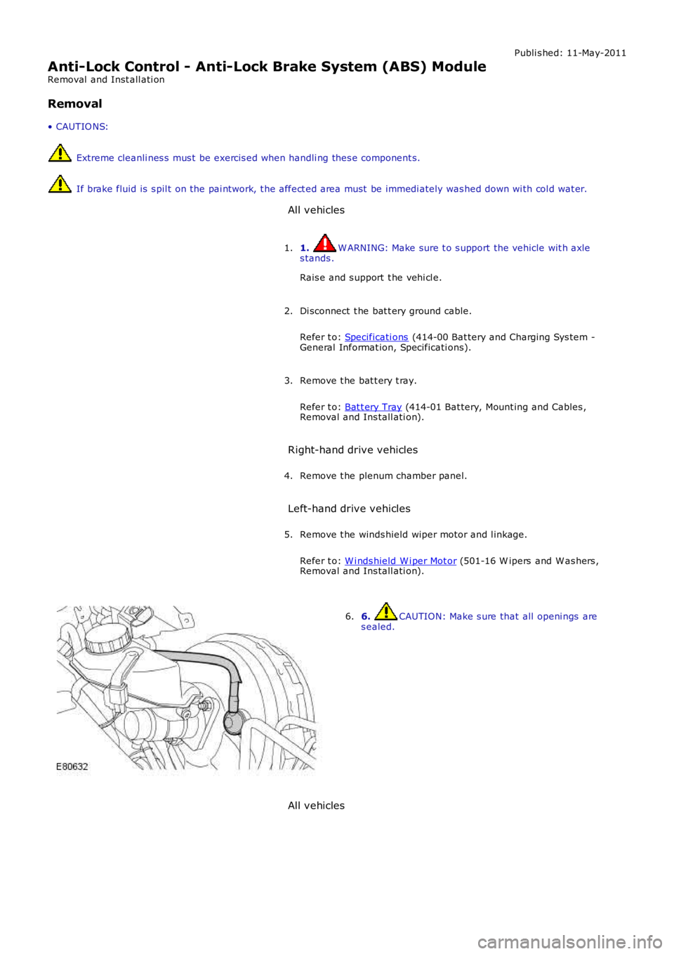
6. CAUTION: Make s ure that all openi ngs ares ealed.6.
All vehicles
Page 2808 of 3229
Wipers and washers
88
L
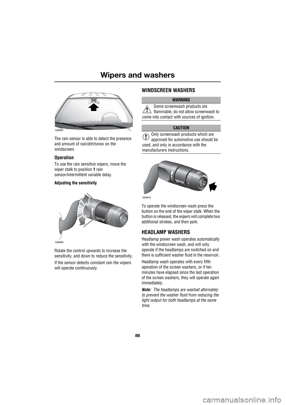
The rain sensor is able to detect the presence
and amount of rain/dirt/snow on the
windscreen.
Operation
To use the rain sensitive wipers, move the
wiper stalk to position 1 rain
sensor/intermittent variable delay.
Adjusting the sensitivity
Rotate the control upwards to increase the
sensitivity, and down to reduce the sensitivity.
If the sensor detects co nstant rain the wipers
will operate continuously.
WINDSCREEN WASHERS
To operate the windscreen wash press the
button on the end of the wiper stalk. When the
button is released, the wi pers will complete two
additional strokes, and then park.
HEADLAMP WASHERS
Headlamp power wash operates automatically
with the windscreen wash, and will only
operate if the headlamps are switched on and
there is sufficient washer fluid in the reservoir.
Headlamp wash operates with every fifth
operation of the screen washers, or if ten
minutes have elapsed si nce the last operation
of the screen washers, they will operate again
immediately.
Note: The headlamps are washed alternately
to prevent the washer fluid from reducing the
light output for both headlamps at the same
time.
E80687
E80684
WARNING
Some screenwash products are
flammable, do not allow screenwash to
come into contact with sources of ignition.
CAUTION
Only screenwash products which are
approved for automotive use should be
used, and only in accordance with the
manufacturers instructions.
E80679
Page 2810 of 3229
Wipers and washers
90
L
Blocked jets
If a washer jet becomes blocked, use a thin
strand of wire to unblock the jet by inserting
the wire into the jet. Ensure that the wire is
completely remove d after unblocking.
CHECKING THE WIPER BLADES
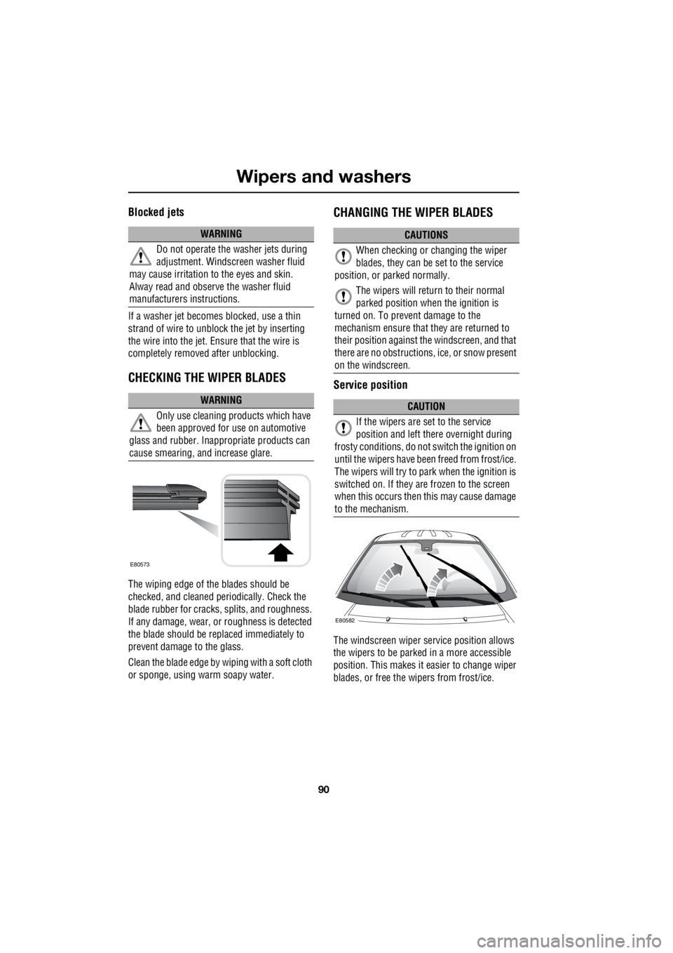
The wiping edge of the blades should be
checked, and cleaned pe riodically. Check the
blade rubber for cracks , splits, and roughness.
If any damage, wear, or roughness is detected
the blade should be repl aced immediately to
prevent damage to the glass.
Clean the blade edge by wiping with a soft cloth
or sponge, using warm soapy water.
CHANGING THE WIPER BLADES
Service position
The windscreen wiper se rvice position allows
the wipers to be parked in a more accessible
position. This makes it ea sier to change wiper
blades, or free the wipers from frost/ice.
WARNING
Do not operate the washer jets during
adjustment. Windscreen washer fluid
may cause irritation to the eyes and skin.
Alway read and observe the washer fluid
manufacturers instructions.
WARNING
Only use cleaning pr oducts which have
been approved for use on automotive
glass and rubber. Inappr opriate products can
cause smearing, and increase glare.
E80573
CAUTIONS
When checking or changing the wiper
blades, they can be set to the service
position, or parked normally.
The wipers will return to their normal
parked position when the ignition is
turned on. To prevent damage to the
mechanism ensure that they are returned to
their position against th e windscreen, and that
there are no obstructions, ice, or snow present
on the windscreen.
CAUTION
If the wipers are set to the service
position and left there overnight during
frosty conditions, do not switch the ignition on
until the wipers have been freed from frost/ice.
The wipers will try to park when the ignition is
switched on. If they are frozen to the screen
when this occurs then this may cause damage
to the mechanism.
E80582
Page 2878 of 3229

Maintenance
158
L
One or both types of serv ice interval (distance
and time) may be displayed. For example, if an
engine oil service is du e based on mileage, and
a brake fluid change is due based on time, both
distance and time c ountdowns will display.
Service Portfolio
The Service Portfolio book includes a Service
Record section, which enables a record to be
kept of all the servicing and inspections that are
carried out on the vehicle. This section of the
book also has an area for brake fluid changes
to be recorded.
Ensure your service provider signs and stamps
the book after each se rvice and inspection.
Owner Maintenance
In addition to the routine maintenance, a
number of simple checks must be carried out
more frequently. Advice is given on the pages
that follow.
Daily checks
• Operation of lamps, horn, direction
indicators, wipers, washers and warning
indicators.
• Operation of seat belts and brakes.
• Look for fluid deposits underneath the
vehicle that might indicate a leak.
Weekly checks
• Engine oil level. See ENGINE OIL CHECK
(page 162).
• Engine coolant check. See ENGINE
COOLANT CHECK (page 163).
• Brake/clutch fluid level. See BRAKE AND
CLUTCH FLUID CHECK (page 165). •
Power steering fluid level. See POWER
STEERING FLUID CHECK (page 166).
• Screen washer fluid level. See WASHER
FLUID CHECK (page 167).
• Tyre pressure s and condition.
• Operate air conditioning.
Note: The engine oil leve l should be checked
more frequently if the vehicle is driven for
prolonged periods at high speeds.
Driving in arduous conditions
When a vehicle is operated in extremely
arduous conditions, more frequent attention
must be paid to servicing requirements.
For example, if your vehicle experiences deep
wading conditions, even daily servicing could
be necessary to ensure the continued safe and
reliable operation of the vehicle.
Arduous driving conditions include:
• Driving in dusty and/or sandy conditions.
• Driving on rough and/or muddy roads
and/or wading.
• Driving in extremely hot conditions.
• Towing a trailer or driving in mountainous
conditions.
Contact a Land Rover Dealer/Authorised
Repairer for advice.
Emission control
Your vehicle is fitted with various items of
emission and evaporative control equipment,
designed to meet sp ecific territorial
requirements. You should be aware that
unauthorised replacemen t, modification or
tampering with this equipment by an owner or
repair shop, may be unlawful and subject to
legal penalties.
CAUTION
Any significant or sudden drop in fluid
levels, or uneven tyre wear, should be
reported to a qualified technician without
delay.