2006 LAND ROVER FRELANDER 2 rear view mirror
[x] Cancel search: rear view mirrorPage 106 of 3229
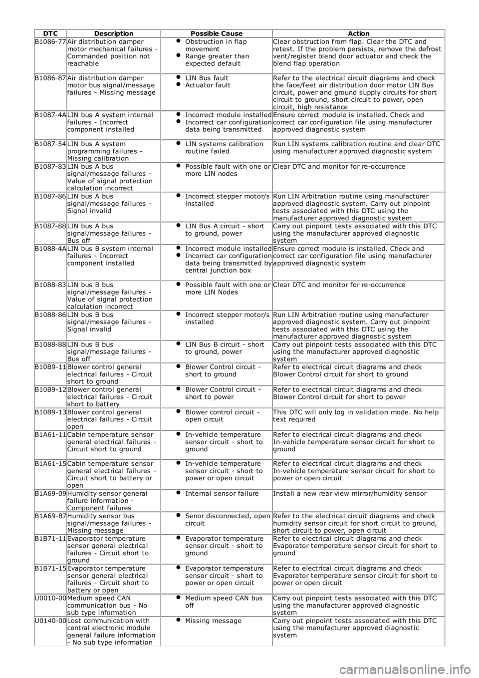
DT CDescriptionPossible CauseAction
B1086-77Air dis t ri but ion dampermot or mechanical fail ures -Commanded pos i ti on notreachabl e
Obs truct ion i n flapmovementRange greater t hanexpected defaul t
Cl ear obs truct ion from fl ap. Cl ear the DTC andretes t. If the problem pers is ts , remove the defros tvent/regis t er bl end door actuat or and check theblend flap operat ion
B1086-87Air dis t ri but ion dampermot or bus s ignal/mes s agefai lures - Mis s ing mes s age
LIN Bus faultAct uator faul tRefer t o t he electrical ci rcuit diagrams and checkt he face/feet ai r dis tribut ion door motor LIN Buscircui t, power and ground s uppl y circuit s for shortcircui t to ground, s hort circui t t o power, opencircui t, hi gh res is t anceB1087-4ALIN bus A s yst em i nternalfai lures - Incorrectcomponent ins tal led
Incorrect modul e ins tal ledIncorrect car configurat iondata bei ng trans mi tt ed
Ens ure correct modul e is ins tall ed. Check andcorrect car configurat ion fil e usi ng manufacturerapproved diagnost ic s ys tem
B1087-54LIN bus A s yst emprogramming failures -Mis s ing cali brat ion
LIN sys t ems cal ibrat ionrout ine failedRun LIN s yst ems cali brati on rout ine and clear DTCus ing manufact urer approved di agnos t ic s yst em
B1087-83LIN bus A buss ignal/mess age fai lures -Value of s ignal protecti oncal cul ati on incorrect
Poss ibl e faul t wit h one ormore LIN nodesCl ear DTC and moni tor for re-occurrence
B1087-86LIN bus A buss ignal/mess age fai lures -Signal inval id
Incorrect s t epper mot or/sins tal ledRun LIN Arbi trati on rout ine us ing manufact urerapproved diagnost ic s ys tem. Carry out pinpointt est s as s ociat ed wi th t his DTC usi ng t hemanufact urer approved di agnos ti c s ys t emB1087-88LIN bus A buss ignal/mess age fai lures -Bus off
LIN Bus A circui t - s hortto ground, powerCarry out pinpoint t es t s as sociat ed wit h t his DTCus ing t he manufacturer approved di agnos ti cs yst em
B1088-4ALIN bus B s yst em i nternalfai lures - Incorrectcomponent ins tal led
Incorrect modul e ins tal ledIncorrect car configurat iondata bei ng trans mi tt ed bycent ral juncti on box
Ens ure correct modul e is ins tall ed. Check andcorrect car configurat ion fil e usi ng manufacturerapproved diagnost ic s ys tem
B1088-83LIN bus B buss ignal/mess age fai lures -Value of s ignal protecti oncal cul ati on incorrect
Poss ibl e faul t wit h one ormore LIN NodesCl ear DTC and moni tor for re-occurrence
B1088-86LIN bus B buss ignal/mess age fai lures -Signal inval id
Incorrect s t epper mot or/sins tal ledRun LIN Arbi trati on rout ine us ing manufact urerapproved diagnost ic s ys tem. Carry out pinpointt est s as s ociat ed wi th t his DTC usi ng t hemanufact urer approved di agnos ti c s ys t em
B1088-88LIN bus B buss ignal/mess age fai lures -Bus off
LIN Bus B circui t - s hortto ground, powerCarry out pinpoint t es t s as sociat ed wit h t his DTCus ing t he manufacturer approved di agnos ti cs yst emB10B9-11Blower cont rol generalelectrical fail ures - Ci rcuits hort to ground
Blower Control circui t -s hort to groundRefer t o elect rical circuit di agrams and checkBl ower Control ci rcuit for short to ground
B10B9-12Blower cont rol generalelectrical fail ures - Ci rcuits hort to bat t ery
Blower Control circui t -s hort to powerRefer t o elect rical circuit di agrams and checkBl ower Control ci rcuit for short to power
B10B9-13Blower cont rol generalelectrical fail ures - Ci rcuitopen
Blower cont rol circui t -open ci rcuitThis DTC wil l onl y log in vali dat ion mode. No hel pt ext requi red
B1A61-11Cabi n t emperature s ensorgeneral el ect ri cal fai lures -Circui t short to ground
In-vehi cl e t emperatures ens or circuit - short toground
Refer t o elect rical circuit di agrams and checkIn-vehicle t emperat ure s ens or circui t for s hort t oground
B1A61-15Cabi n t emperature s ensorgeneral el ect ri cal fai lures -Circui t short to bat tery oropen
In-vehi cl e t emperatures ens or circuit - short topower or open circui t
Refer t o elect rical circuit di agrams and checkIn-vehicle t emperat ure s ens or circui t for s hort t opower or open ci rcuit
B1A69-09Humidi ty s ens or generalfai lure informati on -Component fai lures
Int ernal s ens or fai lureInst all a new rear view mirror/humidi ty s ens or
B1A69-87Humidi ty s ens or buss ignal/mess age fai lures -Mis s ing mess age
Senor dis connected, opencircuitRefer t o t he electrical ci rcuit diagrams and checkhumi di ty sens or ci rcuit for short ci rcuit t o ground,s hort circui t to power, open ci rcuit
B1B71-11Evaporat or temperat ures ens or general el ect ri calfai lures - Ci rcuit s hort t oground
Evaporat or temperat ures ens or circuit - short toground
Refer t o elect rical circuit di agrams and checkEvaporator t emperature s ens or circuit for s hort toground
B1B71-15Evaporat or temperat ures ens or general el ect ri calfai lures - Ci rcuit s hort t obatt ery or open
Evaporat or temperat ures ens or circuit - short topower or open circui t
Refer t o elect rical circuit di agrams and checkEvaporator t emperature s ens or circuit for s hort topower or open ci rcuit
U0010-00Medium speed CANcommunicat ion bus - Nos ub type i nformat ion
Medium speed CAN busoffCarry out pinpoint t es t s as sociat ed wit h t his DTCus ing t he manufacturer approved di agnos ti cs yst em
U0140-00Los t communicati on wi thcent ral electronic modulegeneral fail ure i nformat ion- No s ub t ype informati on
Mis s ing mess ageCarry out pinpoint t es t s as sociat ed wit h t his DTCus ing t he manufacturer approved di agnos ti cs yst em
Page 1922 of 3229
The automat ic headlamp s ys tem uses a li ght s ens or and t he CJB, which are connect ed via the LIN bus t o cont rol t heheadl amp funct ional it y.
A l ight s ens or is incorporated in t he rai n/l ight s ens or located on the i nsi de of the windshi el d, bel ow t he rear view mirror.The wiper s yst em al s o uses the rain/l ight s ens or for aut omati c wiper operati on.For addit ional informat ion, refer t o: W i pers and W as hers (501-16 W ipers and W as hers , Des cri pti on and Operati on).
The li ght sens or meas ures the ambi ent l ight around t he vehi cl e i n a vert ical direct ion and als o the angular li ght l evel fromt he front of t he vehi cle. The rai n/li ght sens or us es vehicle s peed s ignals , wiper s wit ch posi ti on and the park posi ti on of thefront wipers to control the s ys tem.
The automat ic headlamp operat ion us es ambient l ight levels whi ch are moni tored by phot odiodes incorporat ed in t herai n/l ight sens or. The rain/l ight s ens or s ends a li ght s on/off request t o t he CJB on t he LIN bus , which res ponds bys wit chi ng on t he low beam headl amps, front s ide l amps, l icense plate lamps and rear t ail l amps. The aut omat ic headlampsare act ivated under the foll owing condi ti ons :
Twil ightDarknessRainTunnel sUnderground or mult is t ori ed car parks .
Operat ion of t he aut omat ic headl amps requires t he ignit ion t o be on (power mode 6), the l ighti ng cont rol rot ary swi tch t obe i n the 'AUTO' pos it ion and a li ght s on reques t s ignal from t he li ght sens or.
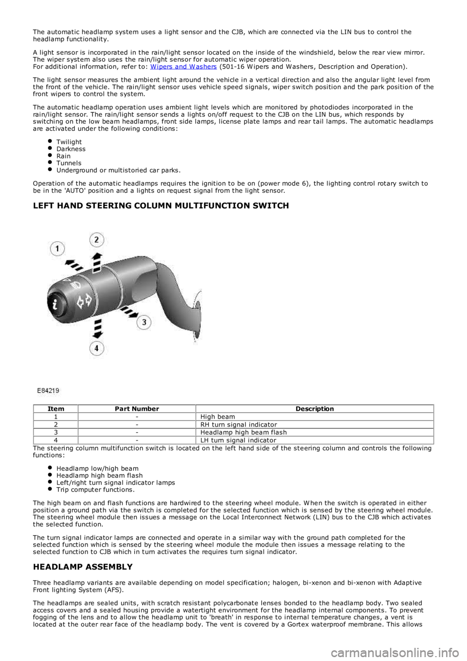
LEFT HAND STEERING COLUMN MULTIFUNCTION SWITCH
ItemPart NumberDescription
1-Hi gh beam
2-RH turn s ignal indicator3-Headlamp hi gh beam flas h
4-LH turn s ignal i ndi cat or
The s teeri ng column mul ti functi on s wit ch is l ocat ed on t he left hand s i de of the s t eering column and cont rols the foll owingfuncti ons :
Headl amp l ow/high beamHeadl amp hi gh beam fl ashLeft /right turn s ignal indicator l ampsTri p comput er functi ons .
The high beam on and fl ash funct ions are hardwi red t o t he s teeri ng wheel modul e. W hen the swi tch i s operat ed in ei therposi ti on a ground pat h via the s wi tch i s compl eted for the s elect ed functi on which is sens ed by t he s teeri ng wheel modul e.The s teeri ng wheel modul e t hen is s ues a mes sage on the Local Interconnect Net work (LIN) bus t o t he CJB which acti vat est he sel ect ed functi on.
The t urn s ignal indicator l amps are connect ed and operate in a si mi lar way wit h t he ground pat h compl eted for thes elect ed funct ion whi ch is s ensed by the s t eering wheel module t he module then i ss ues a mess age rel ati ng to thes elect ed funct ion t o CJB which i n t urn acti vat es t he requires turn s ignal indicator.
HEADLAMP ASSEMBLY
Three headlamp variants are available depending on model s peci fi cat ion; halogen, bi -xenon and bi-xenon wi th Adapt iveFront li ght ing Sys t em (AFS).
The headl amps are sealed uni ts , wit h s crat ch res is t ant polycarbonat e l ens es bonded to the headlamp body. Two s ealedacces s covers and a s ealed housi ng provide a waterti ght environment for the headlamp internal component s . To preventfogging of t he l ens and t o al low t he headlamp unit to 'breath' in res pons e t o i nternal t emperature changes , a vent i slocated at t he outer rear face of the headlamp body. The vent i s covered by a Gort ex wat erproof membrane. This al lows
Page 1953 of 3229
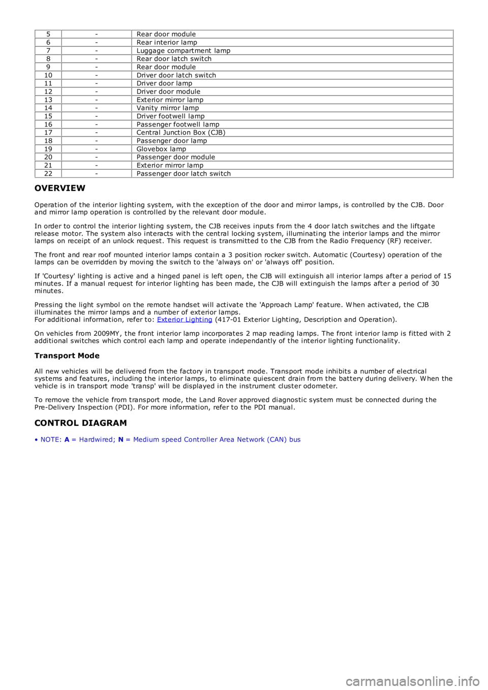
5-Rear door module
6-Rear i nterior lamp
7-Luggage compart ment lamp8-Rear door lat ch swit ch
9-Rear door module
10-Dri ver door lat ch swi tch11-Dri ver door lamp
12-Dri ver door module
13-Ext eri or mirror lamp14-Vani ty mirror l amp
15-Dri ver foot well l amp
16-Pas s enger foot well l amp17-Cent ral Junct ion Box (CJB)
18-Pas s enger door lamp
19-Glovebox lamp20-Pas s enger door module
21-Ext eri or mirror lamp
22-Pas s enger door lat ch swi tch
OVERVIEW
Operat ion of t he int erior l ighti ng s ys t em, wit h t he excepti on of the door and mi rror lamps , is controlled by the CJB. Doorand mi rror l amp operat ion i s cont rol led by t he rel evant door modul e.
In order to cont rol t he int erior l ighti ng s ys t em, the CJB recei ves i nput s from the 4 door l atch s wit ches and the l iftgat erel eas e motor. The s ys tem als o i nt eracts wit h t he cent ral locking s ys tem, i lluminating the interior lamps and the mirrorlamps on receipt of an unlock request . This reques t is trans mi tt ed t o t he CJB from the Radio Frequency (RF) receiver.
The front and rear roof mounted interior lamps contai n a 3 pos i ti on rocker s wi tch. Aut omati c (Courtes y) operati on of thelamps can be overridden by movi ng the s wi tch t o t he 'al ways on' or 'always off' positi on.
If 'Court es y' li ght ing i s acti ve and a hinged panel i s left open, t he CJB wil l ext inguis h all i nterior lamps after a period of 15mi nut es. If a manual request for int erior l ighti ng has been made, t he CJB wi ll exti nguis h the l amps aft er a peri od of 30mi nut es.
Pres s ing t he li ght symbol on t he remot e hands et wi ll act ivat e t he 'Approach Lamp' feat ure. W hen act ivated, t he CJBil lumi nat es t he mirror l amps and a number of ext eri or l amps.For addit ional informat ion, refer t o: Ext eri or Li ght ing (417-01 Ext erior Light ing, Descri pti on and Operat ion).
On vehicles from 2009MY , t he front int erior l amp incorporat es 2 map reading l amps. The front i nt eri or lamp i s fit ted wi th 2addi ti onal s wi tches which cont rol each lamp and operate i ndependant ly of t he i nt eri or light ing funct ionalit y.
Transport Mode
All new vehicles will be del ivered from the factory in t rans port mode. Trans port mode i nhi bit s a number of el ect ri cals ys t ems and feat ures , including t he i nt eri or lamps , to el imi nate qui es cent drain from t he bat t ery duri ng delivery. W hen thevehi cl e i s in trans port mode 't ransp' wi ll be dis played i n the ins trument cl us t er odomet er.
To remove the vehicle from t rans port mode, the Land Rover approved di agnos ti c s ys t em mus t be connect ed during t hePre-Delivery Ins pect ion (PDI). For more i nformati on, refer t o the PDI manual .
CONTROL DIAGRAM
• NOTE: A = Hardwi red; N = Medium s peed Cont roll er Area Net work (CAN) bus
Page 2073 of 3229
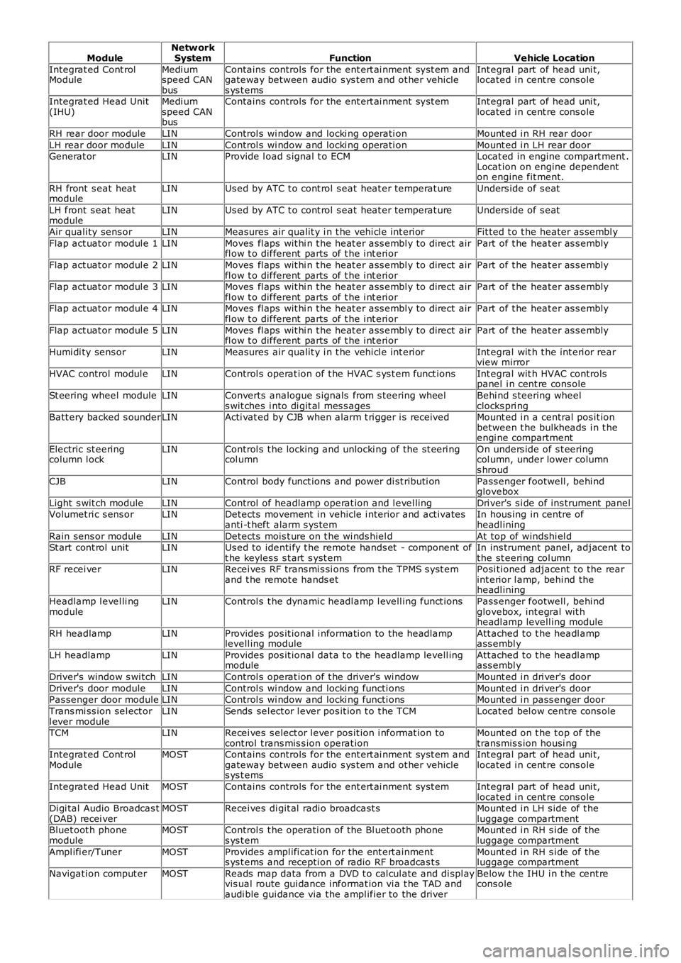
ModuleNetw orkSystemFunctionVehicle Location
Integrat ed Cont rolModuleMedi umspeed CANbus
Contains controls for the ent ert ai nment sys t em andgateway between audio s ys t em and ot her vehicles ys t ems
Int egral part of head uni t,located i n cent re cons ole
Integrat ed Head Unit(IHU)Medi umspeed CANbus
Contains controls for the ent ert ai nment sys t emInt egral part of head uni t,located i n cent re cons ole
RH rear door moduleLINControl s wi ndow and locki ng operati onMount ed i n RH rear door
LH rear door moduleLINControl s wi ndow and locki ng operati onMount ed i n LH rear doorGenerat orLINProvide l oad s ignal t o ECMLocat ed in engine compart ment .Locat ion on engine dependenton engine fit ment.
RH front s eat heatmoduleLINUs ed by ATC t o cont rol s eat heat er temperat ureUnders ide of s eat
LH front s eat heatmoduleLINUs ed by ATC t o cont rol s eat heat er temperat ureUnders ide of s eat
Air quali ty sens orLINMeasures air qualit y i n t he vehi cl e int eri orFit ted t o t he heater as sembl y
Flap act uat or modul e 1LINMoves fl aps wit hi n t he heat er ass embl y to direct airfl ow t o different parts of t he i nt eri orPart of t he heat er as s embly
Flap act uat or modul e 2LINMoves fl aps wit hi n t he heat er ass embl y to direct airfl ow t o different parts of t he i nt eri orPart of t he heat er as s embly
Flap act uat or modul e 3LINMoves fl aps wit hi n t he heat er ass embl y to direct airfl ow t o different parts of t he i nt eri orPart of t he heat er as s embly
Flap act uat or modul e 4LINMoves fl aps wit hi n t he heat er ass embl y to direct airfl ow t o different parts of t he i nt eri orPart of t he heat er as s embly
Flap act uat or modul e 5LINMoves fl aps wit hi n t he heat er ass embl y to direct airfl ow t o different parts of t he i nt eri orPart of t he heat er as s embly
Humi di ty sens orLINMeasures air qualit y i n t he vehi cl e int eri orInt egral wit h t he int eri or rearview mirror
HVAC control modul eLINControl s operat ion of t he HVAC s ys t em funct ionsInt egral wit h HVAC controlspanel i n cent re cons ole
St eering wheel moduleLINConverts analogue s ignals from s teering wheels wit ches i nto di git al mes s agesBehi nd s teering wheelclocks pri ngBatt ery backed s ounderLINActi vat ed by CJB when alarm t ri gger i s receivedMount ed i n a central pos it ionbetween t he bulkheads i n t heengi ne compartment
Electric st eeringcolumn l ockLINControl s t he locking and unlocki ng of the st eeri ngcol umnOn unders ide of s t eeringcol umn, under lower columns hroud
CJBLINControl body funct ions and power di st ributi onPass enger footwell , behi ndglovebox
Light s wit ch moduleLINControl of headlamp operat ion and l evel lingDri ver's s i de of ins trument panelVolumet ri c s ens orLINDetects movement i n vehicle i nterior and act ivatesanti -t heft alarm s ys temIn hous ing in centre ofheadl ining
Rain sens or modul eLINDetects mois t ure on t he wi nds hiel dAt top of windshi el dSt art cont rol unitLINUs ed to identi fy t he remote hands et - component oft he keyles s s t art s yst emIn ins trument panel, adjacent tothe st eeri ng col umnRF recei verLINRecei ves RF trans mi s si ons from t he TPMS s yst emand t he remot e hands etPosi ti oned adjacent t o the rearint erior l amp, behi nd theheadl ining
Headlamp l evel li ngmoduleLINControl s t he dynami c headl amp l evell ing funct ionsPass enger footwell , behi ndglovebox, int egral wit hheadl amp levell ing module
RH headlampLINProvides pos it ional i nformati on to the headlamplevell ing moduleAtt ached t o t he headl ampass embl y
LH headlampLINProvides pos it ional dat a t o t he headlamp levell ingmoduleAtt ached t o t he headl ampass embl y
Driver's window s wi tchLINControl s operat ion of t he driver's wi ndowMount ed i n dri ver's door
Driver's door moduleLINControl s wi ndow and locki ng functi onsMount ed i n dri ver's doorPas senger door moduleLINControl s wi ndow and locki ng functi onsMount ed i n pass enger door
Trans mi ss ion sel ect orl ever moduleLINSends sel ect or l ever pos it ion t o t he TCMLocat ed bel ow centre cons ole
TCMLINRecei ves s elect or l ever pos it ion i nformat ion tocont rol t rans mis s ion operat ionMount ed on t he t op of thetransmis s ion housi ngIntegrat ed Cont rolModuleMOSTContains controls for the ent ert ai nment sys t em andgateway between audio s ys t em and ot her vehicles ys t ems
Int egral part of head uni t,located i n cent re cons ole
Integrat ed Head UnitMOSTContains controls for the ent ert ai nment sys t emInt egral part of head uni t,located i n cent re cons oleDi gi tal Audio Broadcas t(DAB) recei verMOSTRecei ves di git al radi o broadcast sMount ed i n LH s ide of t heluggage compartmentBluet oot h phonemoduleMOSTControl s t he operati on of the Bl uet ooth phones ys t emMount ed i n RH s i de of theluggage compartment
Ampl ifi er/TunerMOSTProvides ampl ifi cat ion for the ent ert ainments ys t ems and recepti on of radio RF broadcas t sMount ed i n RH s i de of theluggage compartment
Navigati on comput erMOSTReads map data from a DVD t o cal cul ate and di spl ayvis ual route gui dance i nformat ion vi a t he TAD andaudi ble gui dance via the ampl ifier to the driver
Below t he IHU i n t he cent recons ole
Page 2129 of 3229
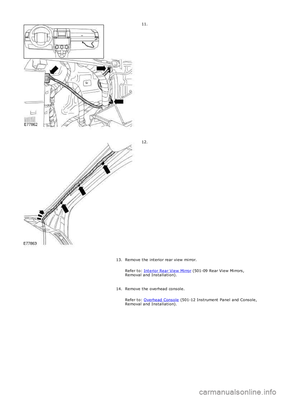
11.
12.
Remove t he int erior rear vi ew mi rror.
Refer t o: Int erior Rear View Mirror (501-09 Rear Vi ew Mi rrors ,Removal and Ins tall ati on).
13.
Remove t he overhead cons ol e.
Refer t o: Overhead Cons ole (501-12 Ins trument Panel and Cons ole,Removal and Ins tall ati on).
14.
Page 2134 of 3229
Inst all t he ti re pres sure monit ori ng s ys t em receiver.
3.
4. NOTE: Thi s s tep requires the ai d of anot her techni ci an.
Inst all t he headl iner.
4.
Connect t he was her jet hos e.
5.
At tach t he front door s eal s .
6.
At tach t he rear of the headli ner.
7.
Reposi ti on the rear s eat s .
8.
Reposi ti on the front s eats .
9.
Inst all t he pas s enger as s is t handl es .
10.
Inst all t he s un vi s ors .
11.
Inst all t he rear int eri or l amp.
12.
Inst all t he overhead cons ol e.
Refer t o: Overhead Cons ole (501-12 Ins trument Panel and Cons ole,
Removal and Ins tall ati on).
13.
Inst all t he int erior rear vi ew mi rror.
Refer t o: Int erior Rear View Mirror (501-09 Rear Vi ew Mi rrors ,
Removal and Ins tall ati on).
14.
Connect t he headl iner wiring harnes s and s ecure t he cl ips .
15.
Inst all t he s peaker gril le.
16.
Inst all t he cowl s ide trim panel .
Refer t o: Cowl Si de Tri m Panel (501-05 Interior Tri m and
Ornament ati on, Removal and Ins tal lat ion).
17.
Inst all t he glove compartment .
Refer t o: Glove Compart ment (501-12 Ins trument Panel and
Consol e, Removal and Ins t al lat ion).
18.
Inst all t he rear quart er t ri m panel.
19.
Inst all t he loadspace s ecuring ring and t ight en the Torx s crew.
T orque: 25 Nm 20.
Inst all t he D-pi llar t ri m panels .
Refer t o: D-Pi llar Trim Panel (501-05 Int eri or Trim and
Ornament ati on, Removal and Ins tal lat ion).
21.
Page 2138 of 3229
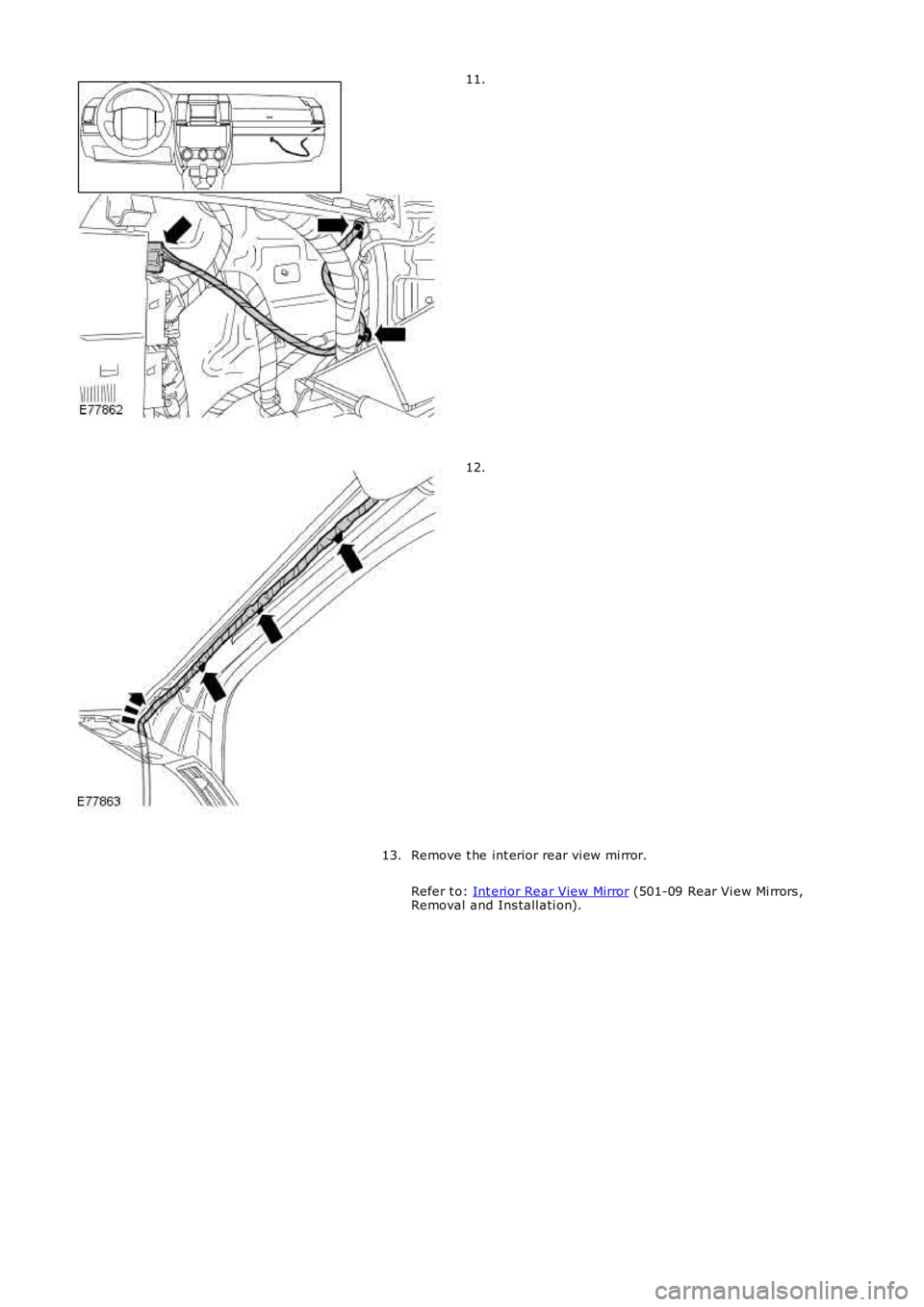
11.
12.
Remove t he int erior rear vi ew mi rror.
Refer t o: Int erior Rear View Mirror (501-09 Rear Vi ew Mi rrors ,
Removal and Ins tall ati on).
13.
Page 2144 of 3229
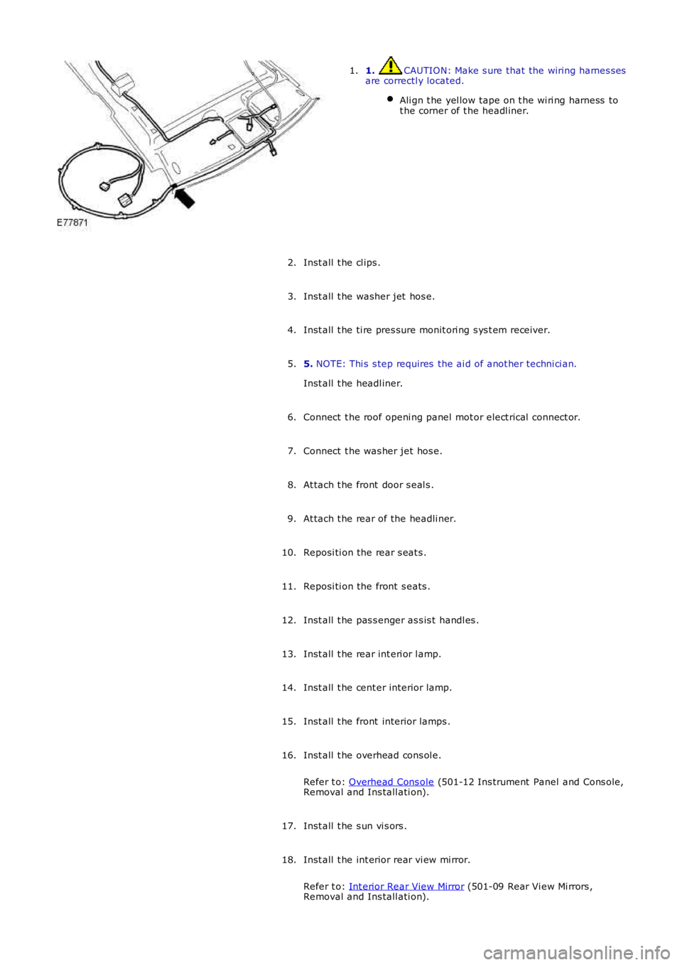
1. CAUTION: Make s ure that the wiring harnes s es
are correctl y located.
Ali gn t he yel low tape on t he wi ri ng harness to
t he corner of t he headl iner. 1.
Inst all t he cl ips .
2.
Inst all t he washer jet hos e.
3.
Inst all t he ti re pres sure monit ori ng s ys t em receiver.
4.
5. NOTE: Thi s s tep requires the ai d of anot her techni ci an.
Inst all t he headl iner.
5.
Connect t he roof openi ng panel mot or elect rical connect or.
6.
Connect t he was her jet hos e.
7.
At tach t he front door s eal s .
8.
At tach t he rear of the headli ner.
9.
Reposi ti on the rear s eat s .
10.
Reposi ti on the front s eats .
11.
Inst all t he pas s enger as s is t handl es .
12.
Inst all t he rear int eri or l amp.
13.
Inst all t he cent er interior lamp.
14.
Inst all t he front interior lamps .
15.
Inst all t he overhead cons ol e.
Refer t o: Overhead Cons ole (501-12 Ins trument Panel and Cons ole,
Removal and Ins tall ati on).
16.
Inst all t he s un vi s ors .
17.
Inst all t he int erior rear vi ew mi rror.
Refer t o: Int erior Rear View Mirror (501-09 Rear Vi ew Mi rrors ,
Removal and Ins tall ati on).
18.