2006 LAND ROVER FRELANDER 2 rear view mirror
[x] Cancel search: rear view mirrorPage 2178 of 3229
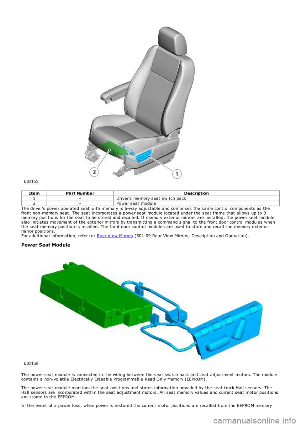
Item
Part Number Description
1 -Driver's memory s eat s wi tch pack
2 -Power s eat modul e
The dri ver's power operated seat wi th memory i s 6-way adjust able and compri s es the s ame cont rol components as the
front non-memory seat . The seat i ncorporat es a power s eat modul e located under the s eat frame that all ows up to 3
memory posi ti ons for t he seat t o be s t ored and recall ed. If memory exteri or mirrors are ins tall ed, the power s eat modul e
als o i nit iates movement of t he ext eri or mirrors by transmit ti ng a command s ignal to the front door control modul es when
t he seat memory pos it ion i s recalled. The front door control modul es are us ed t o s to re and recall t he memory exteri or
mi rror pos it ions .
For addit ional informat ion, refer t o: Rear Vi ew Mi rrors (501-09 Rear View Mirrors , Des cript ion and Operat ion).
Power Seat Mod ule The power seat module is connected in t he wi ri ng bet ween t he s eat s wi tch pack and se
at adjus t ment motors. The module
cont ains a non-vol at il e Elect ricall y Eras able Programmable Read Onl y Memory (EEPROM) .
The power seat module moni tors t he s eat pos it ions and s tores informat ion provided by the s eat track Hal l s ens ors . The
Hall s ensors are incorporated wit hi n t he s eat adjus t ment motors . Al l s eat memory val ues and current s eat mot or pos it ions
are st ored i n t he EEPROM.
In the event of a power los s, when power i s res tored t he current mot or pos it ions are recall ed from t he EEPRO M memory
Page 2185 of 3229
6
-St art control modul e
PRINCIPLES OF OPERATION
Front Power Operated Non-Memory Seats
The dri ver's non-memory s eat wil l operate i n all i gni ti on power modes . The pas senger non-memory seat wi ll only operat e
when t he ignit ion i s i n power mode 6 (Ignit ion).
Power for front pas s enger s eat operat ion is s upplied from t he AJB via a pas s enger s e at power relay t o t he pas s enger s eat
cont rol s wit ch pack. Power for t he driver's s eat operat ion is s upplied di rectl y from the AJB t o t he dri ver's s eat cont rol
s wit ch pack. The front pas s enger and dri ver s eat power suppli es are controlled by th e CJB. The s eat s wi tch pack direct s the
volt age to t he relevant s eat adjus tment mot or when a s eat control swit ch is pres s ed. Two pins wi thin each of t he s eat
s wit ch packs cont rol t he s eat motors. Bot h pins are normal ly connect ed to ground.
The dri ver and pas senger s wit ch packs are al s o connected i n circui t wit h a bat tery-s aver t imer relay t hat i s located in, and
cont rol led by t he CJB. The bat tery-s aver t imer relay all ows operati on of the driver and pas s enger s eat cont rols for 10
mi nut es aft er the engine is s wit ched off, and the i gni ti on is then s elected t o an ap propriat e power mode. The 10 minute
t imer is res et if t he appropriat e i gni ti on power mode is retai ned and the driver's d oor i s opened or clos ed. The driver and
pass enger s eat operati on is inhibit ed i mmediat el y fol lowi ng cent ral locking of t he v ehi cl e.
Operat ing a seat mot or control swit ch appli es volt age to one of t he pins whi le t he o t her pi n remai ns connect ed t o ground.
Operat ing t he s eat motor cont rol s wit ch in the oppos it e direct ion reverses the power and ground connecti ons to the mot or,
all owing t he mot or pi ni on t o rot ate in t he oppos i te di recti on. In t he event t hat a m ot or sei zes or s t icks , an i nternal
t hermal cut -out s wit ch wil l trip to remove volt age from t he mot or.
Driver's Power Operated Memory Seat
The dri ver's memory s eat wil l operat e when t he i gni ti on is in power modes 4 (Acces so ry) and 6 (Ignit ion), and wi ll not
operate during power mode 9 (Engine crank).
Power for the driver's memory s eat operat ion i s s uppl ied di rectl y from t he AJB t o t h e power s eat module. The memory s eat
s wit ch pack i s connected t o t he power seat module that cont rol s t he operati on and me mory pos it ion of t he i ndi vi dual s eat
mot ors . The power s eat module i s connected on the medi um s peed CAN bus t o t he CJB an d the front LH and RH door
cont rol modules .
The power seat module is als o connect ed in ci rcuit wi th a batt ery-saver ti mer rel ay that is locat ed wi thin, and controlled by
t he CJB. The batt ery-saver ti mer rel ay allows operat ion of t he s eat cont rols for 10 mi nut es aft er the engine is s wi tched off,
and t he ignit ion i s t hen sel ect ed to an appropri at e power mode. The 10 minut e t imer i s res et if t he appropri at e i gni ti on
power mode is retai ned and the driver's door i s opened or clos ed. The driver's s eat operat ion is i nhi bit ed immedi ately
fol lowing cent ral locki ng of the vehicl e.
Reques t s for memory exterior mirror movements for a memory recal l are t rans mit ted on the medi um s peed CAN bus by t he
power seat module to t he front door control modul es. The front door cont rol modules direct ly control the memory s t ore and
recall pos it ions for t he memory ext eri or mirrors.
For addit ional informat ion, refer t o: Rear Vi ew Mi rrors (501-09 Rear View Mirrors , Des cript ion and Operat ion).
Power Seat Mod ule
The power seat module features driver s electable funct ions , and aut omat ic monit ori ng functi ons .
Driver Selectable Functions
Seat and ext erior mirror memory recall Immediat e s eat adjus t ment.
Seat and exterior mirror memory recall function
The memory recall functi on s ets t he driver's seat t o a s t ored pos it ion, and is acti v at ed when a swi tch pack memory
posi ti on butt on is pres sed. W hen memory recal l i s i ni ti ated, only 2 seat adjus tment mot ors wil l operat e at any one t ime to
li mit the overall current cons umpti on. To furt her minimize t he current l oad as the m otors energize, the i nit iati on of each of
t he 2 operati ng mot ors i s phas ed wi th a 10 mill is econd del ay. The cushi on s lide and backres t wil l move fi rs t , foll owed by
t he cus hion height .
As s oon as t he seat s wit ch pack memory pos it ion but ton is pres s ed, a mes sage i s t ran s mit ted by the power s eat modul e
on t he medium s peed CAN bus to the front door control modul es. The door cont rol modu les t hen act ivat e t he memory
recall pos it ions for t he exteri or mirrors. The i nst rument clus t er mess age cent er wil l di s pl ay memory recall mes s ages when
a memory recall i s acti vat ed.
The memory recall functi on operates wit h 2 s eparate modes; t he operat ion of each mod e is dependant on t he vehicle
s tat us when the seat memory posi ti on butt on is pres sed.
Memory recall operati ng modes:
One-t ouch mode Proport ional mode.
One-Touch Mode
W hen t he vehicle i s s tat ionary and a s wit ch pack memory pos it ion butt on i s pres sed, t he memory recall functi on wil l
operate in 'one-touch' mode. One t ouch mode all ows the seat and exterior mirrors t o immediatel y move t o t he request ed
s tored memory pos i ti on.
If a s eat adjus t ment or memory pos it ion but ton i s operat ed during memory recal l 'one -t ouch' mode, t he current memory
recall wi ll be cancell ed and t he seat (and ext eri or mirrors via t he medium s peed CAN bus) wi ll i mmediat el y s top movi ng.
The s eat will t hen commence movi ng in the di recti on that corresponds to the press ed s wi tch.
Page 2247 of 3229
Publi s hed: 11-May-2011
Glass, Frames and Mechanisms - Windshield Glass
Removal and Inst all ati on
Removal
Remove t he int erior mi rror.
Refer t o: Int erior Rear View Mirror (501-09 Rear Vi ew Mi rrors ,Removal and Ins tall ati on).
1.
Remove t he A-pi llar t ri m panels .
Refer t o: A-Pil lar Tri m Panel (501-05 Int erior Trim andOrnament ati on, Removal and Ins tal lat ion).
2.
Remove t he plenum chamber panel.
Refer t o: Plenum Chamber (412-01 Cl imat e Control, Removal andInst all at ion).
3.
Di sconnect t he heat ed front s creen elect rical connect ors , if i ns t alled.4.
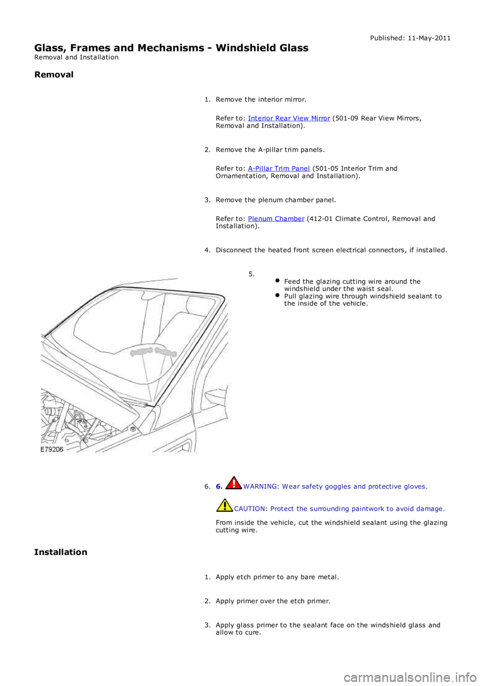
Feed the gl azi ng cutt ing wi re around thewi nds hiel d under t he wais t s eal.Pull glazing wire through winds hi eld s ealant t ot he ins ide of t he vehi cle.
5.
6. W ARNING: W ear safety goggles and prot ecti ve gl oves .
CAUTION: Prot ect the s urroundi ng paintwork t o avoi d damage.
From ins ide the vehicle, cut the wi ndshi el d s ealant usi ng the gl azi ngcutt ing wi re.
6.
Installation
Apply et ch pri mer to any bare met al .1.
Apply primer over the et ch pri mer.2.
Apply gl as s primer t o t he s eal ant face on t he winds hield gl ass andall ow t o cure.3.
Page 2248 of 3229
Apply acti vat or over t he old sealant on t he wi nds hiel d glas s andall ow t o cure.4.
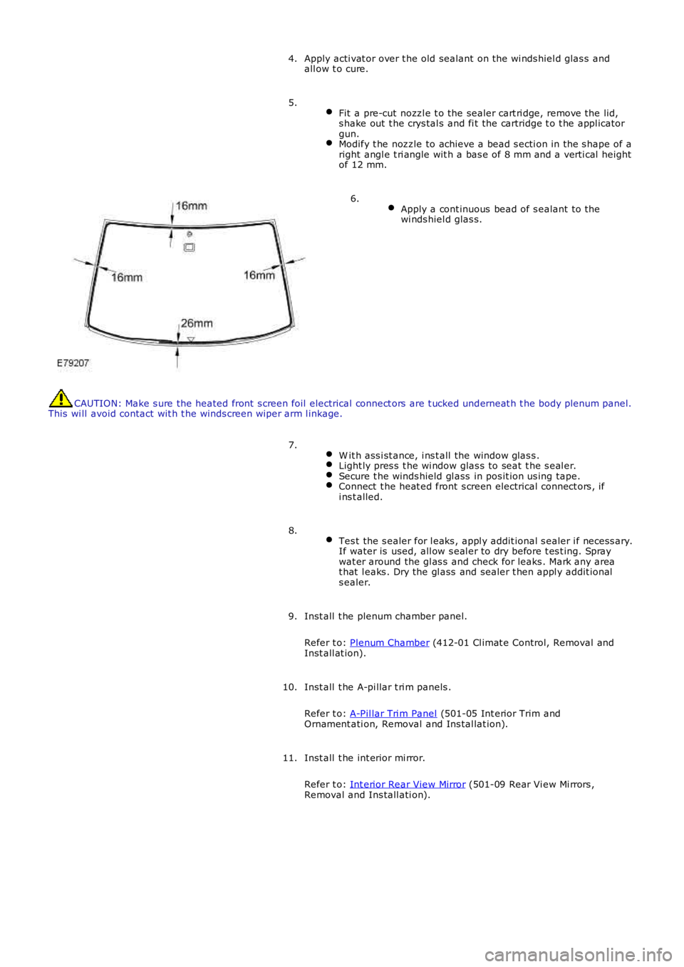
Fit a pre-cut nozzl e t o the sealer cart ri dge, remove the lid,s hake out t he crys tal s and fi t the cartridge t o t he appl icatorgun.Modify t he nozzle to achieve a bead s ecti on in the s hape of aright angl e t ri angle wit h a bas e of 8 mm and a verti cal heightof 12 mm.
5.
Apply a cont inuous bead of s ealant to thewi nds hiel d glas s.
6.
CAUTION: Make s ure the heated front s creen foil electrical connect ors are t ucked underneat h t he body plenum panel.This wi ll avoid contact wit h t he winds creen wi per arm l inkage.
W it h ass i st ance, i ns t all the window glas s .Light ly pres s t he wi ndow glas s to seat t he s eal er.Secure t he winds hield gl ass in pos it ion us ing tape.Connect t he heat ed front s creen electrical connect ors , ifi ns t alled.
7.
Tes t the s ealer for l eaks , appl y addit ional s ealer i f necess ary.If water is used, all ow s eal er to dry before t es t ing. Spraywat er around the gl as s and check for leaks . Mark any areat hat l eaks . Dry the gl ass and sealer t hen appl y addit ionals ealer.
8.
Inst all t he plenum chamber panel.
Refer t o: Plenum Chamber (412-01 Cl imat e Control, Removal andInst all at ion).
9.
Inst all t he A-pi llar t ri m panels .
Refer t o: A-Pil lar Tri m Panel (501-05 Int erior Trim andOrnament ati on, Removal and Ins tal lat ion).
10.
Inst all t he int erior mi rror.
Refer t o: Int erior Rear View Mirror (501-09 Rear Vi ew Mi rrors ,Removal and Ins tall ati on).
11.
Page 2308 of 3229
OVERVIEW
Al l the vehi cle hinged panels are secured by lat ches with mating st rikers. The lat ches incorporat e panel ajar s wi tches t hatwi ll i nform the dri ver of an open acces s point .
The central locking s ys tem is operat ed by eit her t he remot e handset, front door central locking but tons or t he inst rumentpanel central locki ng s wi tches . The central locking s ys tem cont rols the automatic locking and unlocki ng of t he vehicl e ent rypoints. The soft ware used to cont rol t he cent ral l ocking syst em is i ncorporat ed within t he CJB.
The central locking s ys tem is al so integrat ed with t he interior l ighti ng functi on. The i nt eri or light s and exterior mirror lampsare i lluminated via t he RF recei ver and CJB following a val id unlock reques t from the remote hands et .For addit ional informat ion, refer t o: Interior Light ing (417-02 Interior Lighting, Des cri pt ion and Operation).
If configured by the deal er, the exterior door mirror power fold function is al so operat ed by the central locki ng s yst em.
A concealed mechanical door lock is provided in t he front LH door exteri or handle, and i s used to gain acces s to the vehicle ifthe battery is discharged or t he central l ocking syst em fail s.
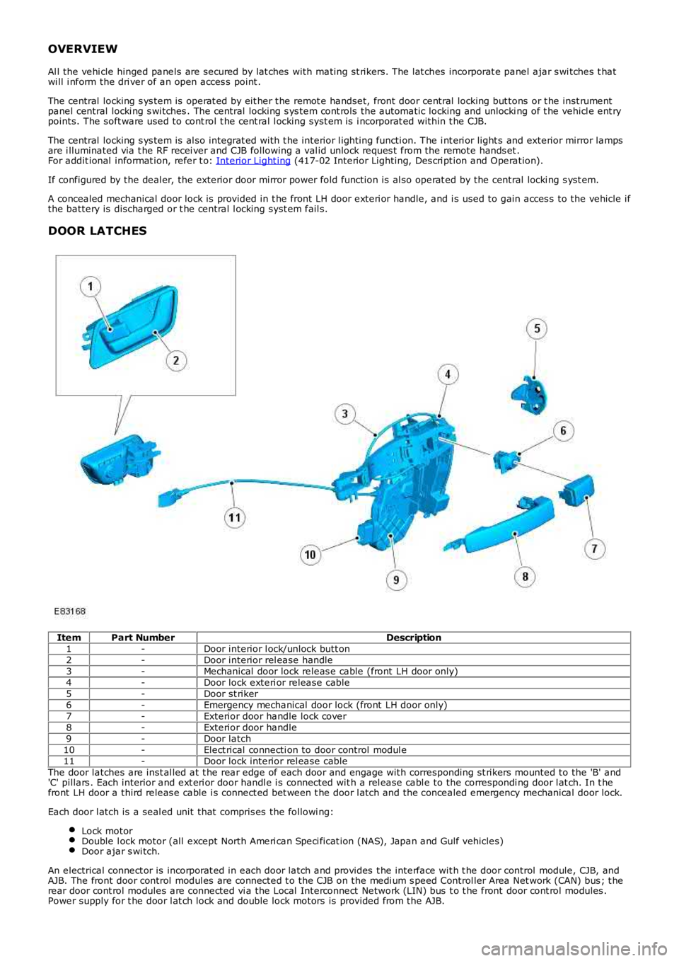
DOOR LATCHES
ItemPart NumberDescription1-Door interior l ock/unlock butt on2-Door interior rel ease handle3-Mechanical door lock releas e cable (front LH door only)4-Door lock exteri or release cable5-Door st riker6-Emergency mechanical door lock (front LH door only)7-Exterior door handle lock cover8-Exterior door handle9-Door latch10-Elect rical connecti on to door control modul e11-Door lock interior rel ease cableThe door latches are inst al led at t he rear edge of each door and engage with corresponding st rikers mounted to the 'B' and'C' pillars . Each interior and ext eri or door handl e i s connected wit h a rel ease cable to the correspondi ng door l at ch. In t hefront LH door a third releas e cable i s connect ed bet ween t he door l atch and the concealed emergency mechanical door lock.
Each door l atch is a seal ed unit that compris es the followi ng:
Lock motorDouble l ock motor (all except North Ameri can Speci ficat ion (NAS), Japan and Gulf vehicles)Door ajar s wi tch.
An electrical connect or is incorporat ed in each door latch and provides t he interface wit h t he door control module, CJB, andAJB. The front door control modul es are connected t o the CJB on the medi um s peed Control ler Area Net work (CAN) bus ; t herear door cont rol modules are connected vi a the Local Interconnect Network (LIN) bus t o t he front door cont rol modules .Power supply for t he door l at ch lock and double lock motors is provided from the AJB.
Page 2357 of 3229
Publi s hed: 11-May-2011
Wipers and Washers - Rain Sensor
Removal and Inst all ati on
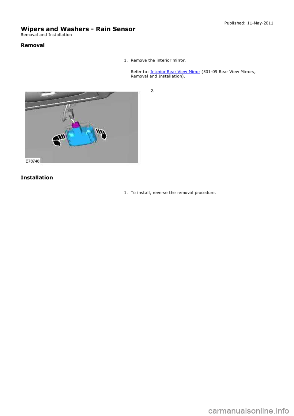
Removal
Remove t he int erior mi rror.
Refer t o: Int erior Rear View Mirror (501-09 Rear Vi ew Mi rrors ,Removal and Ins tall ati on).
1.
2.
Installation
To i nst all , revers e t he removal procedure.1.
Page 2417 of 3229
Publi s hed: 11-May-2011
Roof Opening Panel - Roof Opening Panel Motor
Removal and Inst all ati on
Removal
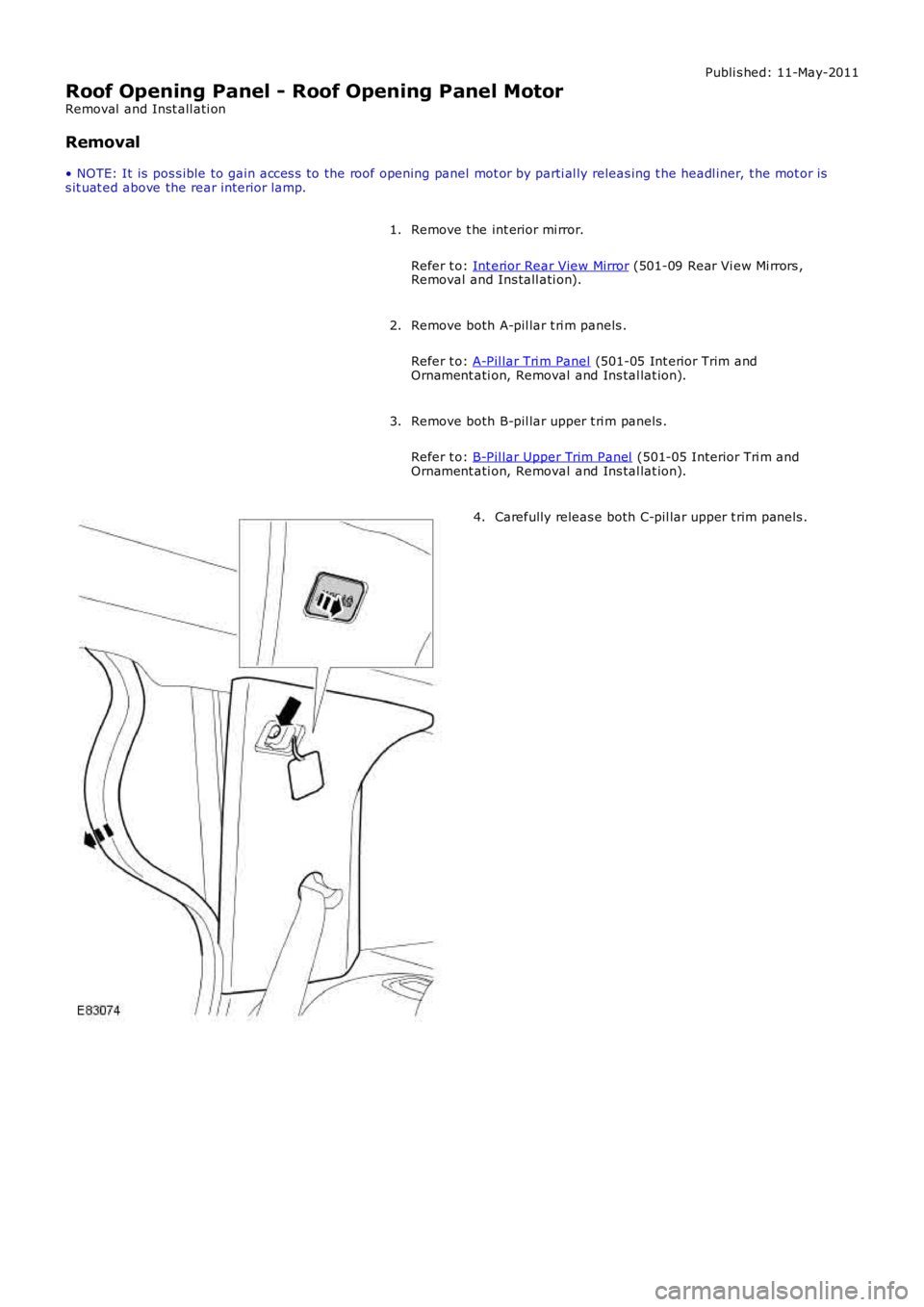
• NOTE: It is pos s ible to gai n acces s to the roof opening panel mot or by parti al ly releas ing t he headl iner, t he mot or iss it uat ed above the rear interior lamp.
Remove t he int erior mi rror.
Refer t o: Int erior Rear View Mirror (501-09 Rear Vi ew Mi rrors ,Removal and Ins tall ati on).
1.
Remove both A-pil lar t ri m panels .
Refer t o: A-Pil lar Tri m Panel (501-05 Int erior Trim andOrnament ati on, Removal and Ins tal lat ion).
2.
Remove both B-pil lar upper t ri m panels .
Refer t o: B-Pil lar Upper Trim Panel (501-05 Interior Tri m andOrnament ati on, Removal and Ins tal lat ion).
3.
Carefully releas e both C-pil lar upper t rim panels .4.
Page 2419 of 3229
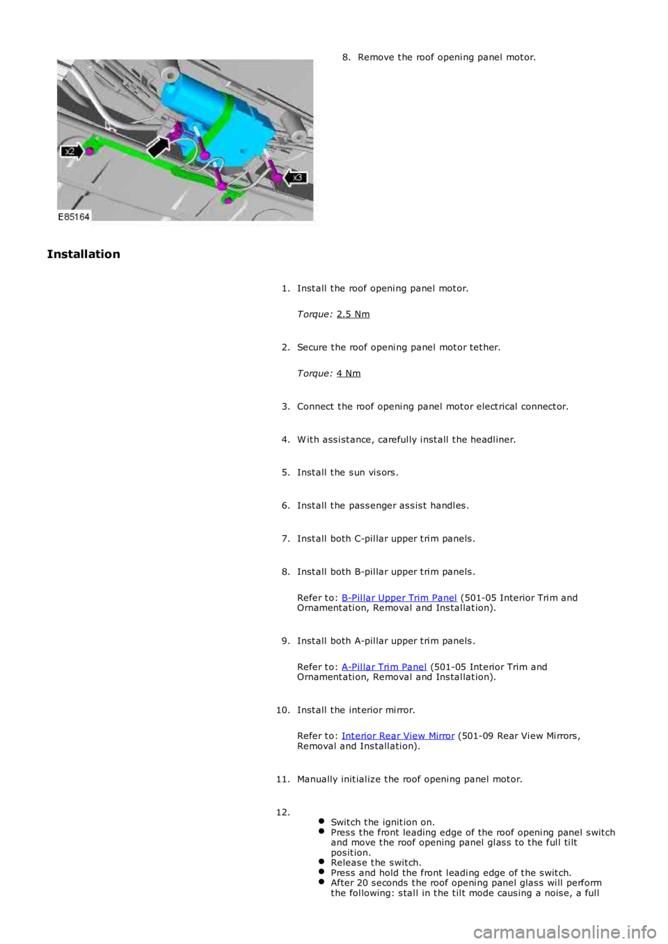
Remove t he roof openi ng panel mot or.
8.
Installation Inst all t he roof openi ng panel mot or.
T orque: 2.5 Nm 1.
Secure t he roof openi ng panel mot or tet her.
T orque: 4 Nm 2.
Connect t he roof openi ng panel mot or elect rical connect or.
3.
W it h ass i st ance, careful ly i nst all t he headl iner.
4.
Inst all t he s un vi s ors .
5.
Inst all t he pas s enger as s is t handl es .
6.
Inst all both C-pil lar upper t ri m panels .
7.
Inst all both B-pil lar upper t ri m panels .
Refer t o: B-Pil lar Upper Trim Panel (501-05 Interior Tri m and
Ornament ati on, Removal and Ins tal lat ion).
8.
Inst all both A-pil lar upper t ri m panels .
Refer t o: A-Pil lar Tri m Panel (501-05 Int erior Trim and
Ornament ati on, Removal and Ins tal lat ion).
9.
Inst all t he int erior mi rror.
Refer t o: Int erior Rear View Mirror (501-09 Rear Vi ew Mi rrors ,
Removal and Ins tall ati on).
10.
Manually init ial ize t he roof openi ng panel mot or.
11.
Swit ch t he ignit ion on. Pres s t he front leading edge of t he roof openi ng panel s wit ch
and move t he roof opening panel gl as s t o t he ful l ti lt
pos it ion. Releas e t he s wit ch.
Pres s and hold the front l eadi ng edge of t he s wit ch.
After 20 s econds t he roof openi ng panel glas s wi ll perform
t he fol lowing: s tal l in t he t il t mode caus ing a nois e, a ful l 12.