2006 LAND ROVER FRELANDER 2 display
[x] Cancel search: displayPage 99 of 3229

Publ is hed: 28-Apr-2011
General Information - Diagnostic Trouble Code (DTC) IndexDTC: Front
Controls Display Interface Module (FCDIM) - Front Integrated Control Panel
Des cript ion and Operat ion
• NOTE: If a cont rol module or component i s s uspect and the vehicl e remai ns under manufacturer warrant y, refer t o t heW arranty Pol icy and Procedures manual (s ect ion B1.2), or determine i f any pri or approval program is i n operat ion, beforet he replacement of a component.
• NOTE: Generic scan t ool s may not read the codes li st ed, or may read only 5-digi t codes . Match t he 5 digi ts from t he s cant ool t o t he fi rs t 5 di gi ts of the 7-digit code li s ted t o i dent ify the fault (the last 2 digi ts gi ve ext ra informati on read by themanufacturer-approved di agnos ti c s ys t em).
• NOTE: W hen performing volt age or res is t ance t est s , always use a digi tal mult imeter (DMM) accurat e t o t hree deci malplaces, and wi th an up-t o-date cal ibrat ion cert ificate. W hen tes ti ng res is t ance al ways take t he res is t ance of t he DMMleads i nt o account .
• NOTE: Check and recti fy bas ic faul ts before beginni ng diagnos t ic rout ines i nvol vi ng pinpoint t es t s.
• NOTE: Ins pect connect ors for s igns of water ingres s , and pins for damage and/or corros ion.
• NOTE: If DTCs are recorded and, aft er performi ng the pi npoi nt tes ts , a fault is not present , an int ermi tt ent concern maybe t he caus e. Always check for loose connect ions and corroded terminals .
Des cript ion And Operat ion
For a detail ed descripti on of the front di spl ay interface s yst em, refer to the relevant Des cri pt ion and Operati on s ect ion i nt he works hop manual .For addit ional informat ion, refer t o: Audi o Sys tem (415-01 Informati on and Entertainment Sys tem, Des cript ion andOperat ion).
Front C ontrol Display Interface Module (FC DIM) (high level display front)
DT CDescriptionPossible CauseAction
U1A01-15Communicati onsli nkNavigati on module t o Hi gh LevelDis play Front communi cat ions li nkcircuit - short to power, opencircuit
Refer t o electrical ci rcuit diagrams and check Navigati onModule t o Hi gh Level Dis play Front communicat ions li nkcircuit for s hort to power, open ci rcuit
U1A4B-48Control modul emi croproces s or 'B'Supervis ion s oft ware fail ureIns t all a new HLDF.For addit ional informat ion, refer t o: Video Di spl ay (415-01Informat ion and Ent ert ai nment Sys t em, Removal andIns t allat ion).
U3000-48Control modul eSupervis ion s oft ware fail ureIns t all a new HLDF.For addit ional informat ion, refer t o: Video Di spl ay (415-01Informat ion and Ent ert ai nment Sys t em, Removal andIns t allat ion).
U3000-4BControl modul eOver temperat ureCheck for addi ti onal DTCs and refer to DTC Index.Check/moni tor s ys tem for re-occurrenceU3000-55Control modul eIncorrect Car Confi gurati on Filedata recei vedCheck/up-dat e Car Confi gurati on File usi ng manufacturerapproved diagnos t ic s yst emU3000-87Control modul eMis s ing mess ageCheck CJB for DTCs and refer t o DTC Index.For addit ional informat ion, refer t o: Communicati onsNetwork (418-00 Modul e Communi cat ions Network,Diagnosi s and Tes ti ng).Check i nformati on and ent ert ainment module for CarConfigurat ion Fi le and MOST network DTCs and refer t orel evant DTC Index. Carry out MOST/CAN net work tes tsus ing t he manufacturer approved diagnost ic sys tem
U3000-98Control modul eComponent or s yst em overt emperatureCheck for addi ti onal DTCs and refer to DTC Index.Check/moni tor s ys tem for re-occurrence
U3003-16Batt ery vol tageCircui t vol tage below thresholdCarry out pinpoi nt tes t s ass ociated wit h t hi s DTC us ingt he manufact urer approved diagnost ic s ys tem
U3003-17Batt ery vol tageCircui t vol tage above t hreshol dCarry out pinpoi nt tes t s ass ociated wit h t hi s DTC us ingt he manufact urer approved diagnost ic s ys tem
Page 1292 of 3229
4-TCM
5-Selector l ever
6-Selector l ever PRND and M/S Li ght Emi tt ing Diode (LED) dis plays7-Hi gh s peed CAN bus to ot her vehi cl e s ys t ems
8-Inst rument clus t er
9-St eering angle sens or10-ABS modul e
11-ECM
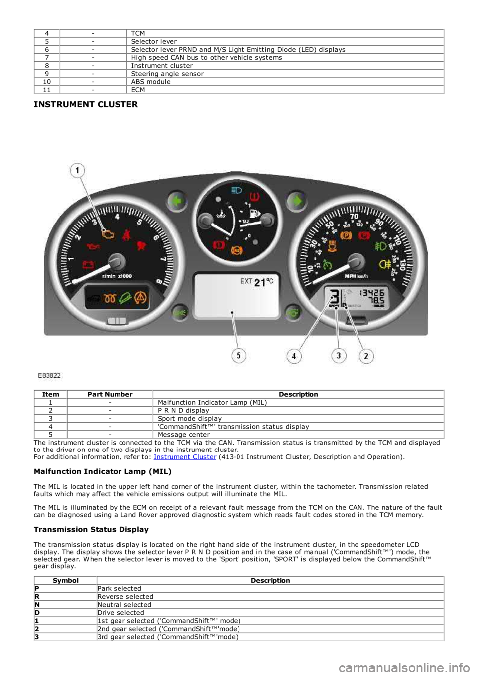
INSTRUMENT CLUSTER
ItemPart NumberDescription
1-Malfunct ion Indicator Lamp (MIL)2-P R N D dis play
3-Sport mode di spl ay
4-'CommandShift™ ' trans mi ss i on s tat us di s pl ay5-Mes s age center
The ins t rument clus ter is connect ed t o t he TCM via the CAN. Trans mi ss ion st atus i s trans mit ted by the TCM and dis playedt o the driver on one of t wo dis plays in the ins trument cl us t er.For addit ional informat ion, refer t o: Ins t rument Clus ter (413-01 Inst rument Cl us t er, Des cript ion and Operat ion).
Malfunction Indicator Lamp (MIL)
The MIL is locat ed in the upper left hand corner of t he ins trument cl ust er, wi thi n the tachometer. Trans mi s si on rel atedfaul ts whi ch may affect t he vehicle emis si ons out put wil l ill uminat e t he MIL.
The MIL is ill uminat ed by the ECM on receipt of a relevant fault mes s age from t he TCM on the CAN. The nature of the faultcan be diagnosed us ing a Land Rover approved diagnos t ic s ys tem which reads faul t codes s t ored i n t he TCM memory.
Transmission Status Display
The t ransmis s ion s t at us dis play i s located on the right hand s ide of t he ins trument cl ust er, i n t he s peedometer LCDdis play. The dis play s hows the sel ect or lever P R N D pos it ion and i n the cas e of manual ('CommandShift™ ') mode, thes elect ed gear. W hen the s elector l ever i s moved to the 'Sport' pos it ion, 'SPORT' i s dis played below the CommandShift™gear di spl ay.
SymbolDescriptionPPark s elect ed
RRevers e s elect ed
NNeutral sel ect edDDrive s elected
11s t gear s elected ('CommandShift™ ' mode)
22nd gear sel ect ed ('CommandShi ft ™'mode)33rd gear s elected ('CommandShift™ 'mode)
Page 1293 of 3229
SymbolDescription
44th gear s elected ('CommandShift™ 'mode)
55th gear s elected ('CommandShift™ 'mode)66th gear s elected ('CommandShift™ 'mode)
SPORTSport mode s elected
Message Center Display
The mes s age center i s located bel ow t he speedometer and t he tachometer at t he bot t om of t he ins trument cl ust er. Themes s age center i s a Liqui d Crys tal Di spl ay (LCD) t o rel ay vehi cl e s tat us informat ion t o t he dri ver.For addit ional informat ion, refer t o: Informat ion and Mes s age Cent er (413-08 Informat ion and Mes s age Cent er, Des cript ionand Operat ion).
CONTROLLER AREA NETWORK (CAN)
The high s peed CAN broadcast bus net work i s us ed to connect t he powert rai n modules . The CAN bus is connect ed betweent he foll owing el ect ronic uni ts :
High Speed CAN Bus
TCMIns t rument clus terSteering angle s ens orRest rai nts control modul eEngi ne Control Module (ECM)ABS moduleAdapt ive Front l ight ing Syst em (AFS) cont rol moduleDiagnost ic socket .
The CAN bus all ows a fast exchange of dat a between modules . The CAN bus compri ses two wires which are identi fied asCAN hi gh (H) and CAN low (L). The t wo wires are colored yel low/bl ack (H) and yell ow/brown (L) and are twi s ted t oget her tomi ni mi se el ect romagneti c int erference (nois e) produced by the CAN bus mes sages .For addit ional informat ion, refer t o: Communicati ons Net work (418-00 Modul e Communicati ons Net work, Des cript ion andOperat ion).
In the event of CAN bus fai lure, t he fol lowi ng s ympt oms may be obs erved:
Trans mis s ion operat es in default modeTorque converter lock-up clut ch cont rol is dis abl edGear pos it ion indicati on in ins trument cl us t er LCD inoperati ve (t his will al so occur wit h any t rans mis s ion faul t).
DRIVING MODES
A number of different dri ving modes are avai lable. Some can be s elected by the driver and some are aut omati cal ly i nit iatedby t he TCM t o adapt t o di fferent drivi ng condit ions .
NormalSportManual 'CommandShift ™'CoolingHil l Descent Cont rol (HDC)Crui seLimp homeCoastFast off recogni ti onUphill and TrailerDownhillW i de Throt tl eTerrai n Res pons eRevers e lock-out
Normal
Normal mode is automat icall y s elect ed by t he TCM when t he i gni ti on is swi tched on. In this mode all automat ic andadapt ive modes are acti ve. Normal mode uses gear s hi ft and l ock-up maps which provi de the opt imum of fuelcons umpt ion, emis s ions and dri veabil it y, depending on t he dri ving s tyl e.
If the t rans mis s ion is operat ed in sport mode or 'CommandShi ft ™' mode and t he s elector lever is moved back t o t he drive'D' pos it ion, then normal mode operat ion is resumed.
Sport
Sport mode provi des enhanced accelerat ion and respons ivenes s by t he us e of s ports shi ft maps . This mode al lows t het ransmis s ion t o down s hift more readil y and hol d gears for longer at hi gher engine speeds .
Manual 'CommandShift™'
Manual 'CommandShift ' mode al lows t he t rans mis s ion t o operat e as a semi -aut omati c trans mi s si on. The driver can changeup and down t he s ix forward gears wi th the freedom of a manual t rans mis s ion.
Shift maps are provi ded to protect t he engi ne at high s peeds . The TCM wi ll automat icall y change up t o a higher gear rat iot o prevent engine overspeed and change down to a lower gear rati o t o avoi d engine l aboring and s t al li ng.
W hen ki ck-down is reques ted the TCM shi ft s down t o t he lowes t avai lable gear. W hen the vehicl e is st ati onary, t he drivercan s el ect 1s t , 2nd or 3rd t o s tart off.
Page 1788 of 3229
Publi s hed: 11-May-2011
Information and Message Center - Information and Message Center
Des cript ion and Operat ion
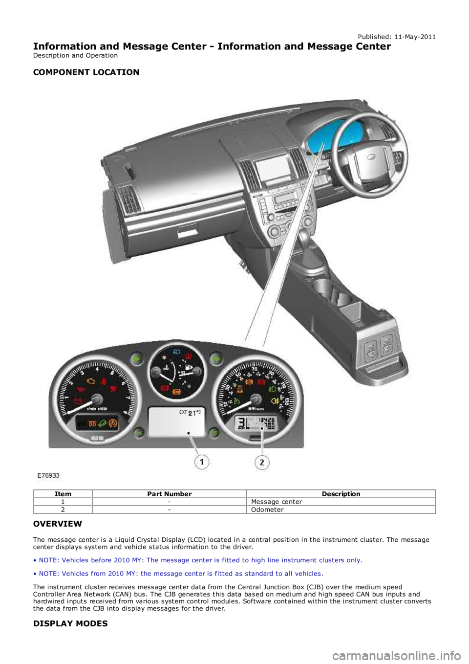
COMPONENT LOCATION
ItemPart NumberDescription1-Mes s age cent er
2-Odomet er
OVERVIEW
The mes s age center i s a Liqui d Crys tal Di spl ay (LCD) located i n a central pos i ti on in t he i ns t rument clus ter. The mes sagecent er dis plays s ys t em and vehicle s t atus i nformat ion to the driver.
• NOTE: Vehicles before 2010 MY : The mes s age center i s fi tt ed t o high line ins trument cl us t ers only.
• NOTE: Vehicles from 2010 MY : the mess age cent er is fit t ed as s tandard t o all vehicles .
The ins t rument clus ter receives mes s age cent er dat a from the Central Juncti on Box (CJB) over t he medium s peedControl ler Area Network (CAN) bus . The CJB generat es t hi s data bas ed on medi um and hi gh speed CAN bus input s andhardwired i nput s received from various s yst em control modul es. Software cont ained within the i nst rument clus t er convertst he dat a from the CJB into dis play mes s ages for the driver.
DISPLAY MODES
Page 1789 of 3229
The mes s age center has 8 di fferent dis play modes as s hown i n the table bel ow.
DisplayModeDescriptionFormat0Bl ankNo dis play
1Pre-checkSys tem pre-check
2NormalAmbi ent ai r temperature dis play only3Trip computerAmbi ent ai r temperature and trip comput er di spl ay
4W arning/St atusmes s ageSt atus and warning i nformat ion onl y
5Terrain Res ponseTerrain Res ponse informat ion available in 3 (A, B, and C) format s depending onact ive functi ons6Not us edNot us ed
7Di agnos ti cTes t images di spl ayed t o check LCD functi on
Display Mode 0
This mode is entered when t he ignit ion i s s wit ched off and t he CAN bus network is asl eep. No characters or symbol s aredis played when in thi s mode. The mode is exi ted when ei ther power mode 6 (ignit ion on) is act ive or t he dri ver enters t hecus t omer configurat ion 'Informati on' mode.
Display Mode 1
This mode is entered when power mode 6 i s fi rs t acti ve. The full s creen mes sage 'SY STEM CHECK IN PRO GRESS' isdis played for approximat ely 3 s econds whil e the ins trument cl us t er carri es out an internal di agnos ti c rout ine. Aft er t he 3s econd t ime period, dis play mode 2 wil l become act ive. If duri ng t he 3 s econd peri od t he ignit ion i s s wit ched off, t hemes s age center wi ll revert back t o dis play mode 0.
Display Mode 2
This i s t he normal operati ng mode of t he mes sage center and wi ll automat ically become acti ve aft er dis play mode 1.
Display Mode 3
This mode is entered by pres s ing t he t ri p comput er but t on when the mess age cent er is in di spl ay mode 2. Trip comput erinformat ion wi ll be di spl ayed for 20 s econds aft er whi ch ti me t he dis play will revert back t o di spl ay mode 2.
Display Mode 4
This mode is entered automat ically if t he mes sage center receives warning or s tat us mes sages from the CJB. The wholes creen is us ed t o dis play warning/s t atus mes s ages , over wri ti ng the ambi ent ai r temperat ure (di spl ay mode 2) and tripcomput er (di spl ay mode 3) informat ion. W arni ng mes sages are dis played for 3 seconds , aft er which t he dis play wi ll ret urnt o the previous dis play mode (2 or 3). St atus mess ages do not ext inguis h unt il t he st atus is rect ified, for example s creenwas h is added t o t he winds hield washer bott le to remove t he 'LOW W ASHER FLUID' mes s age. If more than 1 st atusmes s age is pres ent, t he s creen wi ll s croll t hrough each mes s age at 3 s econd i ntervals.
All current warning/s t atus mes s ages are s croll ed t hrough at 3 s econd i nt ervals when the vehicle fi rs t enters power mode 6,and when t he ignit ion i s s wit ched off. Thes e are dis played in order of priori ty, t he mos t important mes s age bei ngdis played fi rs t .
Display Mode 5
Dis play mode 5 is ent ered when Terrain Respons e is sel ect ed. This mode has 3 format s. Format 5A dis plays t he sameinformat ion as di spl ay mode 3 wi th the addit ion of a Terrai n Respons e icon i n t he top left hand (LH) corner of t he s creen,and a s t eering wheel direct ion i con di s pl ayed centrall y at the top of t he s creen.
Dependi ng on the Terrai n Respons e CAN mes s age received from the CJB, the screen will ent er ei ther dis play mode 5B ordis play mode 5C. W hen in di spl ay mode 5B t he whole screen will be us ed t o dis play Terrain Res ponse mes sages , overwrit ing t he informat ion s hown in mode 5A.
If the s creen adopts di spl ay mode 5C t he t op thi rd of t he s creen wil l dis play all Terrain Res pons e opt ion i cons . The lowert wo t hi rds of t he s creen wil l dis play Terrain respons e mes s ages .
The ins t rument clus ter provides a feedback s ignal to the Terrain Res ponse cont rol module i nforming i t that t he rel evantTerrai n Res pons e i nformat ion is being di s pl ayed. The Terrain Res pons e mes s ages for all 3 di s pl ay mode 5 format s can beoverwri tt en however i f the mess age cent er receives a hi gh priorit y warni ng/s tat us mes sage. If t he mes s age cent er isunabl e t o dis play Terrain Res ponse mess ages due t o thi s occurrence, t he ins trument cl ust er changes t he feedback s ignalt o the cont rol module from a value of 1 to a val ue of 0.
Display Mode 7
Dis play mode 7 is a diagnost ic mode and can onl y be acces s ed usi ng t he Land Rover approved di agnos ti c s yst em. Thediagnost ic routi ne can be found i n '413-00 Ins trument Pack and Panel Ill uminat ion' under the 'Cont ent Model ' menu.
W hen i n dis play mode 7, 4 different patt erns are dis played t o check t hat al l areas of the LCD are funct ional.
MESSAGE PRIORITY
Mes sages are ass i gned priori ti es which are defi ned by the effect on dri vi ng s afely and the funct ional abi li ty of t he vehi cl e.New mes s ages are di spl ayed accompani ed by a chime from t he ins t rument clus ter s ounder. The mes s ages are di vi ded int o3 priori ty groups .
Priority Group 1
Page 1854 of 3229
Publi s hed: 11-May-2011
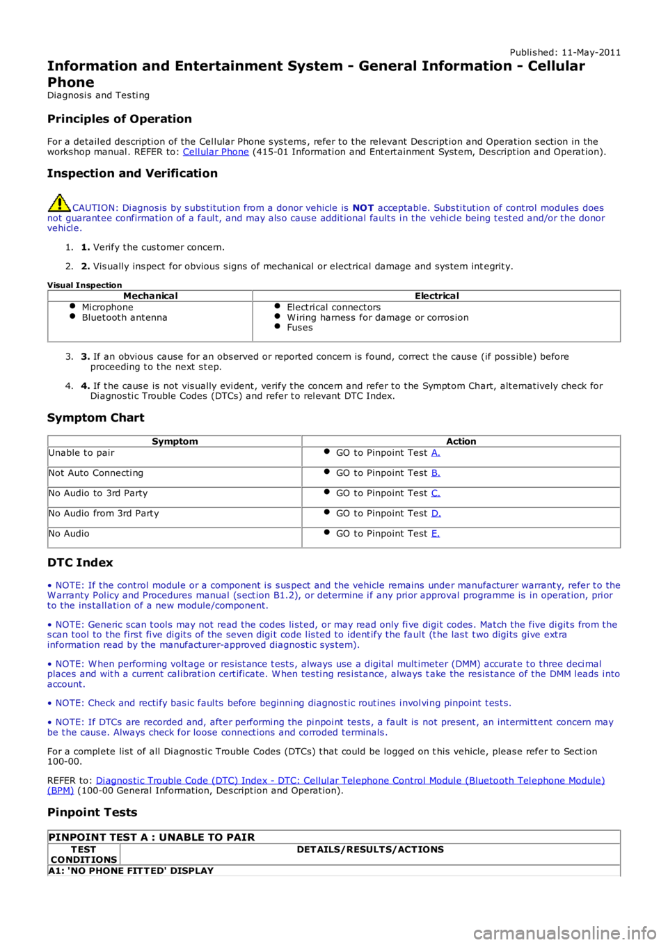
Information and Entertainment System - General Information - Cellular
Phone
Diagnosi s and Tes ti ng
Principles of Operation
For a detail ed descripti on of the Cel lular Phone s ys t ems , refer t o t he rel evant Des cript ion and Operat ion s ecti on in theworks hop manual . REFER to: Cell ular Phone (415-01 Informati on and Ent ert ainment Syst em, Des cript ion and Operat ion).
Inspection and Verification
CAUTION: Di agnos is by s ubs ti tut ion from a donor vehicle is NO T acceptabl e. Subs ti tut ion of cont rol modules doesnot guarant ee confirmat ion of a faul t, and may als o caus e addit ional fault s i n t he vehi cl e being t est ed and/or t he donorvehi cl e.
1. Verify t he cus t omer concern.1.
2. Vis ually ins pect for obvious s igns of mechani cal or electrical damage and sys tem integrit y.2.
Visual InspectionMechanicalElectrical
Mi crophoneBluet oot h ant ennaEl ect ri cal connect orsW iring harnes s for damage or corros ionFus es
3. If an obvious cause for an obs erved or report ed concern is found, correct t he caus e (if pos s ible) beforeproceeding t o t he next s t ep.3.
4. If t he caus e is not vis ually evi dent , verify t he concern and refer t o t he Sympt om Chart, alt ernat ively check forDi agnos ti c Trouble Codes (DTCs) and refer t o rel evant DTC Index.4.
Symptom Chart
SymptomAction
Unable t o pairGO t o Pinpoint Test A.
Not Auto Connecti ngGO t o Pinpoint Test B.
No Audio to 3rd PartyGO t o Pinpoint Test C.
No Audio from 3rd Part yGO t o Pinpoint Test D.
No AudioGO t o Pinpoint Test E.
DTC Index
• NOTE: If the control modul e or a component i s s us pect and the vehicle remains under manufacturer warrant y, refer t o theW arranty Pol icy and Procedures manual (s ect ion B1.2), or determine i f any pri or approval programme is in operat ion, pri ort o the ins tall ati on of a new module/component.
• NOTE: Generic scan t ool s may not read the codes li st ed, or may read only fi ve digit codes . Mat ch the five di git s from t hes can tool to the firs t fi ve di git s of the seven digi t code l is ted to ident ify t he faul t (t he las t t wo digi ts gi ve ext rainformat ion read by the manufact urer-approved diagnost ic s ys tem).
• NOTE: W hen performing volt age or res is t ance t est s , always use a digi tal mult imeter (DMM) accurat e t o t hree deci malplaces and wit h a current cal ibrat ion cert ificate. W hen tes ti ng res i st ance, always take the res is tance of the DMM l eads i ntoaccount.
• NOTE: Check and recti fy bas ic faul ts before beginni ng diagnos t ic rout ines i nvol vi ng pinpoint t es t s.
• NOTE: If DTCs are recorded and, aft er performi ng the pi npoi nt tes ts , a fault is not present , an int ermi tt ent concern maybe t he caus e. Always check for loose connect ions and corroded terminals .
For a compl ete lis t of all Di agnos ti c Trouble Codes (DTCs) t hat could be logged on this vehicle, pleas e refer to Sect ion100-00.
REFER to: Di agnos ti c Trouble Code (DTC) Index - DTC: Cell ul ar Tel ephone Control Modul e (Bluetooth Tel ephone Module)(BPM) (100-00 General Informat ion, Des cript ion and Operat ion).
Pinpoint Tests
PINPOINT TEST A : UNABLE TO PAIR
T ESTCO NDIT IONSDET AILS/RESULT S/ACT IONS
A1: 'NO PHONE FIT T ED' DISPLAY
Page 1855 of 3229
1
1
1
1
1
1
1
1
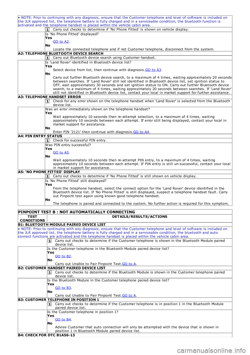
• NOTE: Prior to cont inuing wi th any di agnos is , ens ure t hat the Cus tomer t elephone and level of s oft ware is i ncl uded ont he JLR approved l is t , the t elephone bat tery is full y charged and in a s erviceabl e condi ti on, t he bluet oot h funct ion i sacti vat ed and t he tel ephone hands et is placed wit hin t he vehi cle cabin area.
Carry out checks to det ermi ne if 'No Phone Fit ted' is s hown on vehicle di s pl ay.
Is 'No Phone Fit ted' dis played?YesGO to A2.NoLocat e t he connect ed t elephone and i f not Cus t omer telephone, di sconnect from the sys tem.
A2: T ELEPHONE BLUET OOT H DEVICE SEARCHCarry out Bluetoot h devi ce search us i ng Cust omer hands et.
Is 'Land Rover' i dent ified i n Bl uet oot h device l is t?YesSelect device from li s t, t hen cont inue wi th di agnos is .GO t o A3.NoCarry out further Bluetoot h devi ce s earch, t o a maxi mum of 4 ti mes , wai ti ng approximat ely 20 s econdsbetween s earches. If 'Land Rover' st il l not i dent ified i n Bl uet oot h device l is t, s et igni ti on st atus toOFF, wai t approximat el y 30 s econds and s et ignit ion st atus t o ON. Carry out furt her Bl uet ooth devices earch, t o a maxi mum of 4 ti mes , wait ing approximat ely 20 seconds bet ween s earches . If 'Land Rover's ti ll not identi fi ed in Bl uetooth devi ce lis t , cont act your local i n market s upport for furt her as s is tance.
A3: T ELEPHONE HANDSET ERRORCheck for any error s hown on t he t elephone hands et when 'Land Rover' i s s elect ed from the Bl uetoothdevi ce li st .
W as an error i mmediat el y s hown on t he tel ephone handset ?YesW ai t approxi matel y 10 s econds t hen re-at t empt sel ect ion, to a maximum of 4 t imes , wait ingapproximat el y 10 s econds bet ween each at tempt . If error s ti ll being di spl ayed, cont act your local i nmarket s upport for as s is tance.NoEnter PIN '2121' t hen cont inue wi th diagnos i s.GO t o A4.A4: PIN ENT RY ST AT US
Check for s uccess ful PIN entry.
W as PIN ent ry s ucces s ful?YesGO to A5.NoW ai t approxi matel y 10 s econds t hen re-at t empt PIN ent ry, t o a maximum of 4 t imes, wai ti ngapproximat el y 10 s econds bet ween each at tempt . If PIN ent ry i s s ti ll un-s ucces s ful, contact your l ocalin market s upport for as si st ance.A5: 'NO PHONE FIT T ED' DISPLAY
Carry out checks to det ermi ne if 'No Phone Fit ted' is s t ill s hown on vehicle di s pl ay.
Is 'No Phone Fit ted' s ti ll dis played?YesFrom the telephone hands et, s elect t he connect opt ion for the 'Land Rover' device identi fi ed in theBluet oot h device li s t. If 'No Phone Fit ted' is st il l di s pl ayed, s uspect a t elephone hands et fault . Carryout Pinpoi nt tes t again us ing known good t elephone hands et .NoThe t el ephone i s paired and connect ed t o t he s ys t em. No further acti on is requi red for thi s s ymptom.
PINPOINT TEST B : NOT AUTOMATICALLY CONNECTING
T ESTCONDIT IONSDET AILS/RESULT S/ACT IONS
B1: BLUET OOT H MODULE PAIRED DEVICE LIST
• NOTE: Prior to cont inuing wi th any di agnos is , ens ure t hat the Cus tomer t elephone and level of s oft ware is i ncl uded ont he JLR approved l is t , the t elephone bat tery is full y charged and in a s erviceabl e condi ti on, t he bluet oot h and aut oconnect functi ons are acti vat ed and t he tel ephone handset i s placed wit hin t he vehicle cabin area.
Carry out checks to det ermi ne if t he Cus tomer t elephone is s hown in the Bl uetooth Modul e paireddevi ce li st .
Is the Cus tomer t elephone in t he Bl uet oot h Module pai red device l is t?YesGO to B2.NoCarry out Unabl e t o Pair Pinpoint Test .GO t o A.B2: CUST OMER HANDSET PAIRED DEVICE LIST
Carry out checks to det ermi ne if t he Bl uet oot h Module is s hown i n t he Cus t omer tel ephone paireddevi ce li st .Is the Bl uet ooth Modul e in the Cus tomer t elephone pai red device l is t?YesGO to B3.NoCarry out Unabl e t o Pair Pinpoint Test .GO t o A.
B3: CUST OMER T ELEPHONE IN POSIT ION 1
Carry out checks to det ermi ne if t he Cus tomer t elephone is i n posi ti on 1 i n t he Bluetoot h Modulepaired devi ce lis t .
Is the Cus tomer t elephone in pos it ion 1?YesGO to B4.NoAdvi s e Cust omer t hat aut o connecti on wil l onl y be att empt ed wit h t he devi ce that is shown inposi ti on 1 i n Bluet oot h Module pai red device l is t.
B4: CHECK FOR DT C B1A56-13
Page 1856 of 3229
1
1
1
1
1
1
1
1
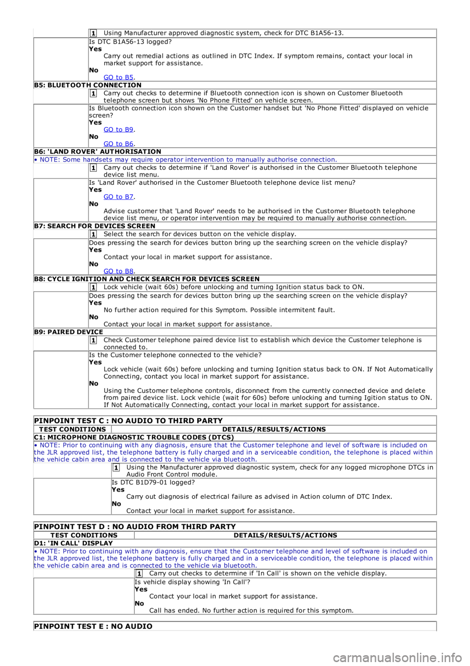
Us ing Manufacturer approved di agnos ti c s ys t em, check for DTC B1A56-13.
Is DTC B1A56-13 logged?YesCarry out remedial acti ons as out li ned in DTC Index. If s ymptom remai ns, contact your l ocal inmarket s upport for as s is tance.NoGO to B5.B5: BLUET OOT H CONNECT ION
Carry out checks to det ermi ne if Bl uet ooth connect ion i con is s hown on Cus tomer Bl uet ootht el ephone s creen but s hows 'No Phone Fit ted' on vehi cle s creen.Is Bluetooth connect ion icon s hown on the Cus t omer hands et but 'No Phone Fi tt ed' di spl ayed on vehi cl es creen?YesGO to B9.NoGO to B6.B6: 'LAND ROVER' AUT HORISAT ION
• NOTE: Some hands et s may require operator int erventi on to manual ly aut horis e connect ion.
Carry out checks to det ermi ne if 'Land Rover' i s authori sed in t he Cus tomer Bluet ooth t elephonedevi ce li st menu.
Is 'Land Rover' aut horis ed i n the Cus t omer Bluetooth tel ephone device li s t menu?YesGO to B7.NoAdvi s e cus t omer that 'Land Rover' needs t o be aut horis ed i n t he Cus t omer Bluetoot h tel ephonedevi ce li st menu, or operator i nterventi on may be required to manual ly authoris e connecti on.
B7: SEARCH FOR DEVICES SCREEN
Select the s earch for devices butt on on t he vehicle di spl ay.
Does pres si ng t he search for devi ces but ton bring up the s earching s creen on t he vehicle di spl ay?YesContact your l ocal in market s upport for ass i st ance.NoGO to B8.B8: CYCLE IGNIT ION AND CHECK SEARCH FOR DEVICES SCREEN
Lock vehicle (wai t 60s ) before unlocki ng and t urning Ignit ion s tat us back to O N.
Does pres si ng t he search for devi ces but ton bring up the s earching s creen on t he vehicle di spl ay?YesNo furt her acti on required for t his Sympt om. Poss ibl e int ermi tent faul t.NoContact your l ocal in market s upport for ass i st ance.B9: PAIRED DEVICE
Check Cus t omer t elephone pai red device l is t t o es tabli sh which devi ce the Cus t omer telephone isconnected t o.Is the Cus tomer t elephone connect ed t o t he vehi cl e?YesLock vehicle (wai t 60s ) before unlocki ng and t urning Ignit ion s tat us back to O N. If Not Automat icall yConnecti ng, contact you local in market support for as s is t ance.NoUs ing t he Cus tomer t el ephone controls , dis connect from t he current ly connect ed devi ce and del et efrom pai red device l is t. Lock vehi cl e (wait for 60s ) before unl ocking and turni ng Igi ti on s tat us to ON.If Not Aut omati cal ly Connect ing, cont act your local i n market s upport for as s is t ance.
PINPOINT TEST C : NO AUDIO TO THIRD PARTY
T EST CONDIT IONSDET AILS/RESULT S/ACT IONS
C1: MICROPHONE DIAGNOST IC T ROUBLE CO DES (DT CS)• NOTE: Prior to cont inuing wi th any di agnos is , ens ure t hat the Cus tomer t elephone and level of s oft ware is i ncl uded ont he JLR approved l is t , the t elephone bat tery is full y charged and in a s erviceabl e condi ti on, t he t elephone is placed wi thint he vehi cl e cabi n area and is connect ed to the vehicle vi a bluet oot h.
Us ing t he Manufacturer approved diagnost ic sys tem, check for any logged mi crophone DTCs i nAudio Front Control modul e.
Is DTC B1D79-01 logged?YesCarry out diagnos is of el ect ri cal failure as advis ed in Act ion column of DTC Index.NoContact your l ocal in market s upport for ass i st ance.
PINPOINT TEST D : NO AUDIO FROM THIRD PARTY
T EST CONDIT IO NSDET AILS/RESULT S/ACT IONS
D1: ' IN CALL' DISPLAY
• NOTE: Prior to cont inuing wi th any di agnos is , ens ure t hat the Cus tomer t elephone and level of s oft ware is i ncl uded ont he JLR approved l is t , the t elephone bat tery is full y charged and in a s erviceabl e condi ti on, t he t elephone is placed wi thint he vehi cl e cabi n area and is connect ed to the vehicle vi a bluet oot h.Carry out checks t o determine i f 'In Call ' i s s hown on t he vehi cl e dis play.
Is vehi cl e dis play s howing 'In Call'?YesContact your l ocal in market s upport for as si s tance.NoCall has ended. No further act ion i s requi red for this sympt om.
PINPOINT TEST E : NO AUDIO