2006 LAND ROVER FRELANDER 2 display
[x] Cancel search: displayPage 1859 of 3229
1
t o the ins tall ati on of a new module/component.
• NOTE: Generic scan t ool s may not read the codes li st ed, or may read only fi ve digit codes . Mat ch the five di git s from t hes can tool to the firs t fi ve di git s of the seven digi t code l is ted to ident ify t he faul t (t he las t t wo digi ts gi ve ext rainformat ion read by the manufact urer-approved diagnost ic s ys tem).
• NOTE: W hen performing volt age or res is t ance t est s , always use a digi tal mult imeter (DMM) accurat e t o t hree deci malplaces and wit h a current cal ibrat ion cert ificate. W hen tes ti ng res i st ance, always take the res is tance of the DMM l eads i ntoaccount.
• NOTE: Check and recti fy bas ic faul ts before beginni ng diagnos t ic rout ines i nvol vi ng pinpoint t es t s.
• NOTE: Ins pect connect ors for s igns of water ingres s , and pins for damage and/or corros ion.
• NOTE: If DTCs are recorded and, aft er performi ng the pi npoi nt tes ts , a fault is not present , an int ermi tt ent concern maybe t he caus e. Always check for loose connect ions and corroded terminals .
Informat ion and Ent ert ai nment Modul e (Low Line)
REFER to: Di agnos ti c Trouble Code (DTC) Index - DTC: Infotai nment Cont rol Modul e (ICM) - Low Li ne (100-00 GeneralInformat ion, Des cript ion and Operat ion).
Informat ion and Ent ert ai nment Modul e (High Line)
REFER to: Di agnos ti c Trouble Code (DTC) Index - DTC: Infotai nment Cont rol Modul e (ICM) - High Line (100-00 GeneralInformat ion, Des cript ion and Operat ion).
Audio Front Control Modul e (ACM)
REFER to: Di agnos ti c Trouble Code (DTC) Index - DTC: Audio Front Cont rol Modul e (ACM) (100-00 General Informati on,Des cript ion and Operat ion).
Audio Ampl ifier Modul e (AAM)
REFER to: Di agnos ti c Trouble Code (DTC) Index - DTC: Audio Ampl ifier Module (AAM) (100-00 General Informati on,Des cript ion and Operat ion).
Front Control Di s pl ay Int erface Modul e (FCDIM) (hi gh level di s pl ay front)
REFER to: Di agnos ti c Trouble Code (DTC) Index - DTC: Front Controls Di spl ay Int erface Module (FCDIM) - Front Int egratedControl Panel (100-00 General Informati on, Des cript ion and Operat ion).
Navigati on Cont rol Module (NCM)
REFER to: Di agnos ti c Trouble Code (DTC) Index - DTC: Navigati on Cont rol Module (NAV) (100-00 General Informat ion,Des cript ion and Operat ion).
Satell it e Radio Modul e (SRM)
REFER to: Di agnos ti c Trouble Code (DTC) Index - DTC: Satel lit e Di git al Audio Radi o Syst em Module (SARM) (100-00General Informat ion, Descri pti on and Operat ion).
Digi tal Audio Broadcast Modul e (DAB)
REFER to: Di agnos ti c Trouble Code (DTC) Index - DTC: Digi tal Audio Broadcas t Modul e (DABM) (100-00 GeneralInformat ion, Des cript ion and Operat ion).
High Defini ti on Tuner Module (HDR)
REFER to: Di agnos ti c Trouble Code (DTC) Index - DTC: High Defini ti on Radi o Module (HDR) (100-00 General Informat ion,Des cript ion and Operat ion).
Pinpoint Tests
• NOTE: Vis uall y ins pect for any of t he fol lowi ng condit ions and rect ify any faul t identi fied prior t o carryi ng out any tes tson t he MOST Net work.
Any s harp bends in the opt ical fibre harnes s (check for t hi s before dis turbing any module or connect or)Incorrect engagement of any opti cal connect orsIncorrect engagement of any elect rical connectorsDamage t o t he opt ical fi bre harnes s (chafing, abrasi on, ki nki ng, cuts , break, etc)Incorrect as s embly of t he opti cal network
• NOTE: Unles s ot herwis e s t at ed, ens ure vehi cl e igni ti on st atus is s et to 'ON' when carryi ng out MOST Network t est s .
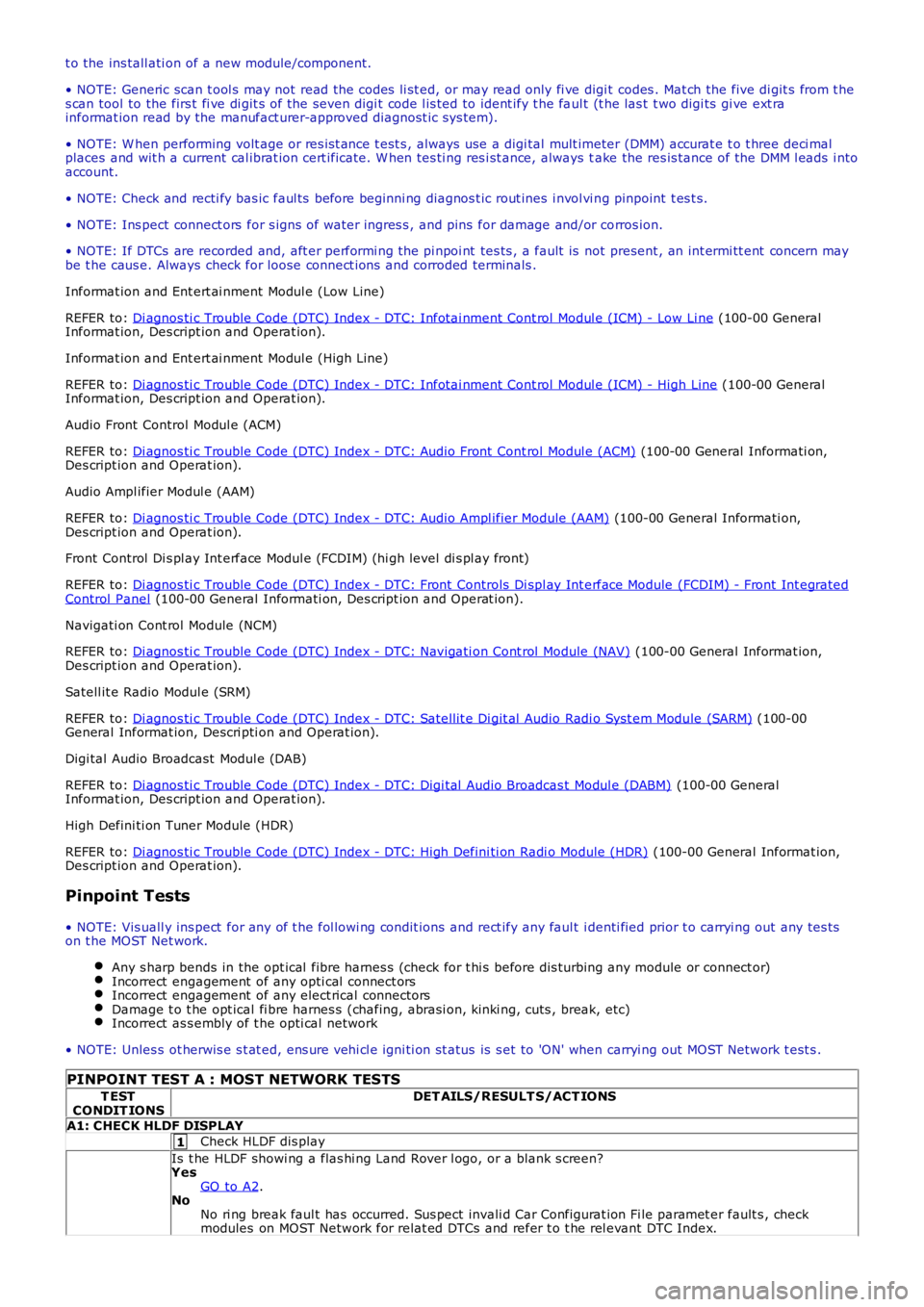
PINPOINT TEST A : MOST NETWORK TESTS
T ESTCONDIT IONSDET AILS/RESULT S/ACT IONS
A1: CHECK HLDF DISPLAY
Check HLDF dis play
Is t he HLDF showi ng a flas hi ng Land Rover l ogo, or a blank s creen?YesGO to A2.NoNo ri ng break faul t has occurred. Sus pect invali d Car Configurat ion Fi le paramet er fault s , checkmodules on MOST Network for relat ed DTCs and refer t o t he rel evant DTC Index.
Page 1863 of 3229
1
1
1
1
1
1
1
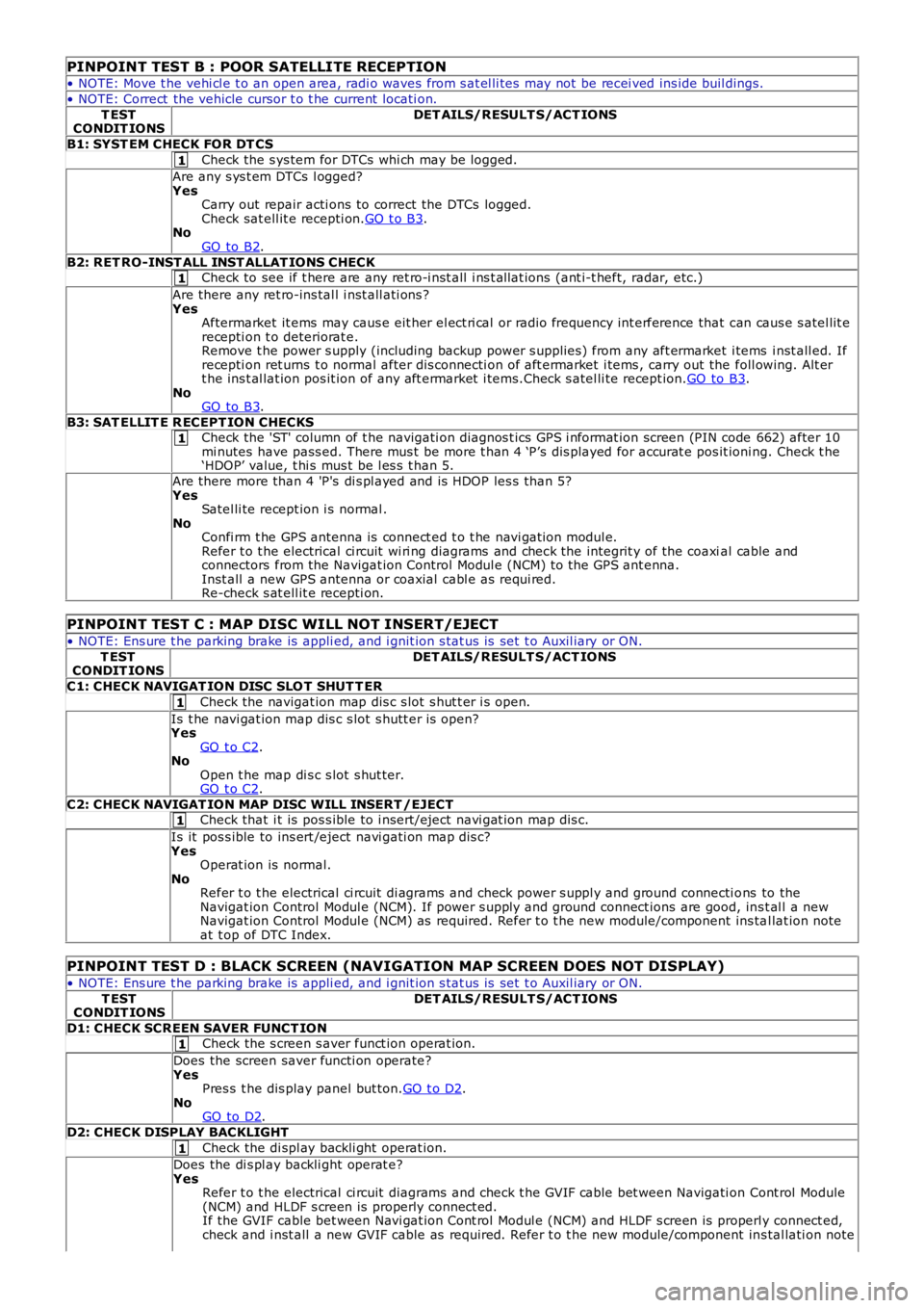
PINPOINT TEST B : POOR SATELLITE RECEPTION
• NOTE: Move t he vehi cl e t o an open area, radi o waves from s at el li tes may not be recei ved ins ide buil dings.
• NOTE: Correct the vehicle cursor t o t he current locati on.
T ESTCONDIT IONSDET AILS/RESULT S/ACT IONS
B1: SYST EM CHECK FOR DT CS
Check the s ys tem for DTCs whi ch may be logged.
Are any s ys t em DTCs l ogged?YesCarry out repair acti ons to correct the DTCs logged.Check sat ell it e recepti on.GO t o B3.NoGO to B2.
B2: RET RO-INST ALL INST ALLAT IONS CHECKCheck to see if t here are any ret ro-i nst all i ns t allat ions (ant i-t heft, radar, etc.)
Are there any ret ro-ins tal l i nst all ati ons ?YesAftermarket it ems may caus e eit her el ect ri cal or radio frequency int erference that can caus e s atel lit erecepti on t o deteriorat e.Remove t he power s upply (including backup power s upplies ) from any aft ermarket i tems i nst all ed. Ifrecepti on ret urns t o normal after dis connecti on of aft ermarket i tems , carry out the foll owing. Alt ert he ins t al lat ion pos it ion of any aft ermarket i tems.Check s atel li te recept ion.GO to B3.NoGO to B3.
B3: SAT ELLIT E R ECEPT ION CHECKSCheck the 'ST' column of t he navigati on diagnos t ics GPS i nformat ion screen (PIN code 662) after 10mi nutes have pass ed. There mus t be more t han 4 ‘P’s dis played for accurat e pos it ioning. Check t he‘HDOP’ value, t hi s mus t be l es s t han 5.
Are there more than 4 'P's di s pl ayed and is HDOP les s than 5?YesSatel li te recept ion i s normal .NoConfi rm t he GPS antenna is connect ed t o t he navi gat ion modul e.Refer t o t he electrical ci rcuit wi ri ng diagrams and check the integrit y of the coaxial cable andconnectors from the Navigat ion Control Modul e (NCM) to the GPS ant enna.Inst all a new GPS antenna or coaxial cabl e as requi red.Re-check s at ell it e recepti on.
PINPOINT TEST C : MAP DISC WILL NOT INSERT/EJECT
• NOTE: Ens ure t he parking brake is appli ed, and i gnit ion s tat us is set t o Auxil iary or ON.
T ESTCONDIT IONSDET AILS/RESULT S/ACT IONS
C1: CHECK NAVIGAT ION DISC SLO T SHUT T ER
Check the navigat ion map dis c s lot s hut t er i s open.
Is t he navi gat ion map dis c s lot s hutt er is open?YesGO t o C2.NoOpen t he map di s c s lot s hut ter.GO t o C2.
C2: CHECK NAVIGAT ION MAP DISC WILL INSERT /EJECTCheck that i t is pos s ible to i nsert/eject navi gat ion map dis c.
Is it pos s ible to ins ert /eject navi gati on map dis c?YesOperat ion is normal.NoRefer t o t he electrical ci rcuit di agrams and check power s uppl y and ground connecti ons to theNavigat ion Control Modul e (NCM). If power s upply and ground connect ions are good, ins t al l a newNavigat ion Control Modul e (NCM) as required. Refer t o t he new module/component ins tal lat ion noteat t op of DTC Index.
PINPOINT TEST D : BLACK SCREEN (NAVIGATION MAP SCREEN DOES NOT DISPLAY)
• NOTE: Ens ure t he parking brake is appli ed, and i gnit ion s tat us is set t o Auxil iary or ON.
T ESTCONDIT IONSDET AILS/RESULT S/ACT IONS
D1: CHECK SCREEN SAVER FUNCT IONCheck the s creen s aver funct ion operat ion.
Does the screen saver functi on operate?YesPres s t he dis play panel but ton.GO t o D2.NoGO to D2.
D2: CHECK DISPLAY BACKLIGHT
Check the di spl ay backli ght operat ion.
Does the di s pl ay backli ght operat e?YesRefer t o t he electrical ci rcuit diagrams and check t he GVIF cable bet ween Navigati on Cont rol Module(NCM) and HLDF s creen is properly connect ed.If the GVIF cable bet ween Navi gat ion Cont rol Modul e (NCM) and HLDF s creen is properly connect ed,check and i nst all a new GVIF cable as required. Refer t o t he new module/component ins tal lati on note
Page 1865 of 3229
1
1
1
1
1
1
1
Is t he 'car current posi ti on not st able' sympt om occurri ng in part icul ar locat ions ?YesSi gnal reflecti ons from buil dings or a part icular locati on may be respons ible.NoCarry out pinpoint t est A "Poor Satell it e Recept ion"
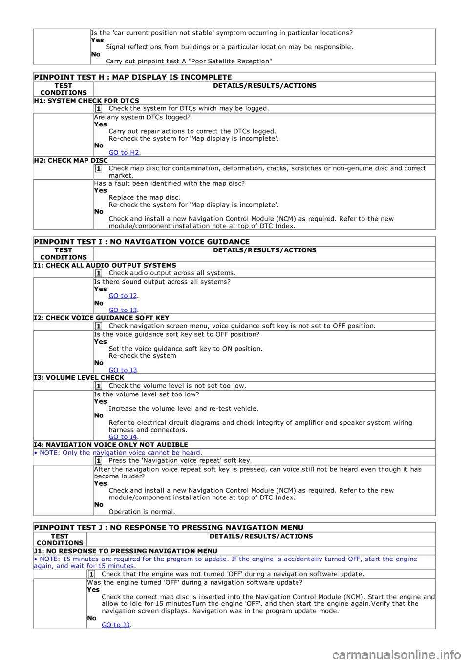
PINPOINT TEST H : MAP DISPLAY IS INCOMPLETE
T ESTCONDIT IONSDET AILS/R ESULT S/ACT IONS
H1: SYST EM CHECK FOR DT CSCheck t he sys t em for DTCs whi ch may be l ogged.
Are any s yst em DTCs l ogged?YesCarry out repai r act ions t o correct t he DTCs logged.Re-check t he s ys t em for 'Map dis play i s i ncomplet e'.NoGO t o H2.H2: CHECK MAP DISC
Check map di sc for cont aminat ion, deformat ion, cracks , s cratches or non-genui ne dis c and correctmarket.Has a fault been i dent ified wi th the map dis c?YesReplace t he map di sc.Re-check t he s ys t em for 'Map dis play i s i ncomplet e'.NoCheck and ins t al l a new Navigat ion Control Modul e (NCM) as required. Refer t o t he newmodul e/component ins t al lat ion not e at top of DTC Index.
PINPOINT TEST I : NO NAVIGATION VOICE GUIDANCE
T ESTCONDIT IONSDET AILS/R ESULT S/ACT IONS
I1: CHECK ALL AUDIO OUT PUT SYST EMSCheck audi o output acros s all s yst ems .
Is t here s ound output across all s ys t ems ?YesGO t o I2.NoGO t o I3.
I2: CHECK VOICE GUIDANCE SO FT KEYCheck navi gat ion screen menu, voice guidance s oft key is not s et t o OFF posi ti on.
Is t he voice guidance soft key set t o OFF pos it ion?YesSet t he voice guidance soft key to O N posi ti on.Re-check t he s ys t emNoGO t o I3.I3: VOLUME LEVEL CHECK
Check t he vol ume l evel is not s et t oo low.
Is t he volume l evel s et too low?YesIncrease the vol ume level and re-tes t vehi cl e.NoRefer to el ect ri cal circui t diagrams and check int egrit y of ampli fier and s peaker s yst em wiringharnes s and connect ors .GO t o I4.
I4: NAVIGAT ION VOICE ONLY NOT AUDIBLE• NOTE: Onl y the navigat ion voice cannot be heard.
Press the 'Navi gat ion voi ce repeat ' s oft key.
After t he navi gat ion voi ce repeat soft key is pres s ed, can voice s t il l not be heard even t hough it hasbecome l ouder?YesCheck and ins t al l a new Navigat ion Control Modul e (NCM) as required. Refer t o t he newmodul e/component ins t al lat ion not e at top of DTC Index.NoO perati on is normal.
PINPOINT TEST J : NO RESPONSE TO PRESSING NAVIGATION MENU
T ESTCONDIT IONSDET AILS/RESULT S/ACT IONS
J1: NO RESPONSE T O PRESSING NAVIGAT ION MENU
• NOTE: 15 minutes are required for t he program t o update. If the engine i s acci dentally turned OFF, s tart the engi neagain, and wait for 15 minut es.
Check t hat t he engine was not t urned 'O FF' during a navi gat ion software updat e.
W as t he engi ne turned 'OFF' during a navigat ion s oft ware updat e?YesCheck t he correct map di sc is i ns erted i nto t he Navigati on Control Module (NCM). Start the engine andal low to idle for 15 mi nut es Turn t he engi ne 'OFF', and t hen s tart the engine again.Verify t hat t henavigat ion s creen dis plays . Navi gat ion was in the program update mode.NoGO t o J3.
Page 1871 of 3229
are di s abl ed.
CD PLAYER
The IAM CD pl ayer i s a 6 di sc mult i changer l ocat ed in the center of t he ins trument panel. The CD mult i changer is capabl eof playing commerci al CDs , CDRs , CDRW s and MP3 di scs .
Random Play
The random pl ay feat ure works in t wo di fferent ways :
Random play of t racks on a CDRandom play of all t racks on any CD i n t he autochanger
The s ingle di s c random feat ure plays all t he tracks on t he s elected CD in a random order. All t he t racks on that dis c wi ll beplayed before a new random s equence is pl ayed. If a new CD is s elected whi le in random mode, the random mode wi ll becancell ed and play wi ll commence from t he fi rs t t rack.
In mult i dis c mode t he IAM us es the current track as the firs t random t rack and wi ll t hen pl ay a furt her 2 tracks (ifavai lable) from thi s CD. The IAM wil l then randoml y s elect anot her CD, and pl ay 3 random tracks . Thi s s equence cont inuesunti l al l tracks from all CD's are played back.
MP3 Function
The CD pl ayer has t he capabil it y to play MP3 fil es . The MP3 di scs foll ow a format of fol ders and fil es wit hin t he fol der. It isals o pos si ble t o pl ace al l the fil es in the root di rectory on t he CD.
The random and repeat features foll ow t he normal CD random and repeat feat ure funct ions .
Automatic Volume Control (AVC)
AVC control s t he audi o volume in relati on t o vehi cl e s peed. As vehicle speed i ncreases t he audi o l evel is adjust ed t ocompens ate for extra road and vehicle noi s e. There are 4 s et t ings for AVC:
OffLowMediumHigh
The default s ett ing is medi um.
Changi ng the AVC level is acces s ed by a l ong pres s of the TONE but t on and sel ect ion of t he AVC us ing t he rot ary encodert o change t he level.
The vehi cl e s peed s ignal i s us ed to enable the ICM to calculat e t he vol ume adjus t ment required. The vehicle s peed s ignalis recei ved over t he medium s peed CAN. The s ignal is an average of t he four wheel s peed s ens or s i gnal s. Should an inval ids peed si gnal be recei ved t he AVC will not alt er the out put volume.
AVC i s cont rol led by t he audi o ampl ifi er.
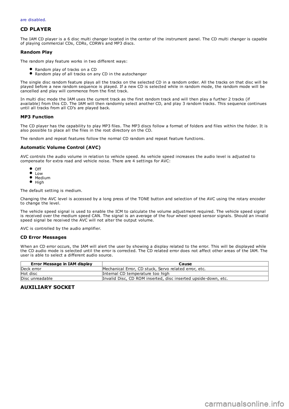
CD Error Messages
W hen an CD error occurs , the IAM wil l al ert t he us er by s howing a dis play related to t he error. This wil l be dis played whilet he CD audio mode is s elected unt il t he error is correct ed. The CD rel at ed error does not affect other areas of t he IAM. Theus er i s able t o s elect a di fferent audi o s ource.
Error Message in IAM displayCause
Deck errorMechanical Error, CD s tuck, Servo rel at ed error, et c.Hot dis cInt ernal CD temperature too hi gh
Di sc unreadableInvalid Dis c, CD ROM ins erted, dis c i nserted ups ide-down, etc.
AUXILIARY SOCKET
Page 1890 of 3229
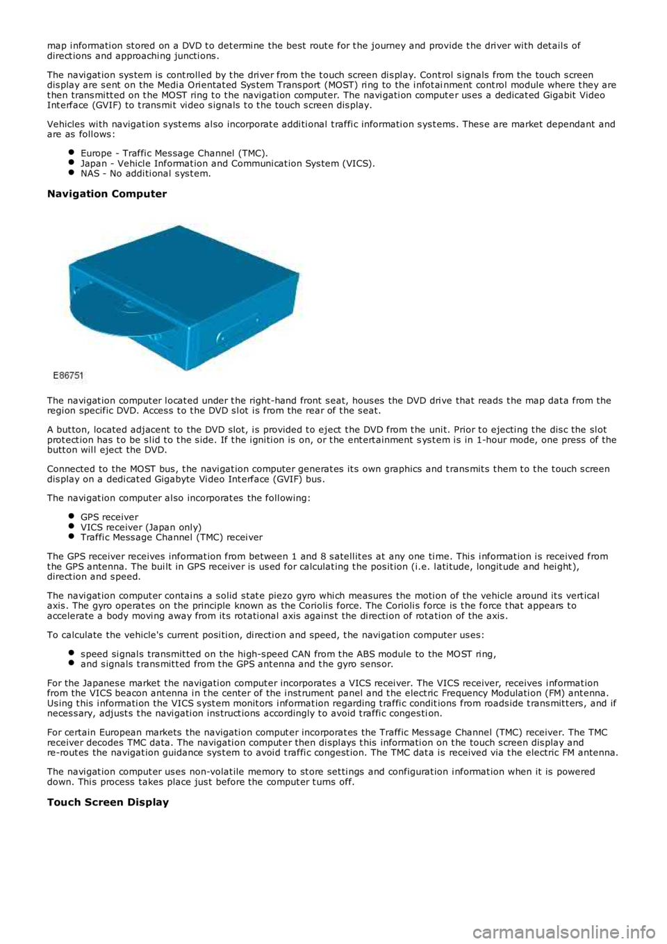
map i nformati on st ored on a DVD t o det ermi ne the bes t rout e for t he journey and provide t he dri ver wi th det ail s ofdirect ions and approachi ng juncti ons .
The navi gat ion sys tem is cont roll ed by t he dri ver from the t ouch screen di s pl ay. Cont rol s ignals from the touch s creendis play are s ent on the Medi a Ori entat ed Sys t em Trans port (MOST) ri ng to the i nfot ainment cont rol module where t hey aret hen trans mi tt ed on t he MOST ring t o t he navi gati on comput er. The navi gati on comput er us es a dedicat ed Gigabit VideoInt erface (GVIF) to t rans mi t vi deo s ignals t o t he touch s creen dis play.
Vehicles wi th navigat ion s yst ems al so incorporat e addi ti onal t raffi c informati on s yst ems . Thes e are market dependant andare as foll ows :
Europe - Traffi c Mes sage Channel (TMC).Japan - Vehicl e Informat ion and Communi cat ion Sys tem (VICS).NAS - No addi ti onal s ys t em.
Navigation Computer
The navi gat ion comput er l ocat ed under t he right-hand front s eat, hous es the DVD dri ve that reads t he map dat a from theregi on specific DVD. Acces s t o t he DVD s l ot i s from the rear of t he s eat.
A but ton, located adjacent to the DVD s lot, i s provided t o eject t he DVD from t he uni t. Prior t o ejecti ng t he dis c the sl otprot ect ion has t o be s l id t o t he s ide. If t he i gni ti on is on, or t he ent ert ainment sys t em i s in 1-hour mode, one press of t hebutt on wil l eject the DVD.
Connected to the MOST bus , t he navi gat ion computer generat es it s own graphics and t rans mit s t hem t o t he t ouch s creendis play on a dedi cat ed Gigabyte Vi deo Int erface (GVIF) bus .
The navi gat ion comput er al so incorporat es the foll owing:
GPS receiverVICS receiver (Japan onl y)Traffi c Mess age Channel (TMC) recei ver
The GPS receiver receives informat ion from between 1 and 8 s atell it es at any one ti me. Thi s i nformat ion i s received fromt he GPS antenna. The bui lt in GPS receiver is us ed for calculat ing t he pos it ion (i.e. l ati tude, longit ude and hei ght ),direct ion and s peed.
The navi gat ion comput er contai ns a s olid s tat e piezo gyro whi ch measures the moti on of the vehicle around it s vert icalaxis . The gyro operat es on the principle known as the Corioli s force. The Corioli s force is t he force t hat appears t oaccelerate a body movi ng away from it s rot ati onal axis agains t the di recti on of rot ati on of the axis .
To calculate the vehicle's current posi ti on, di recti on and s peed, t he navi gat ion computer us es:
s peed si gnal s transmit ted on the hi gh-s peed CAN from t he ABS module to the MO ST ri ng,and s ignals t rans mit t ed from t he GPS ant enna and t he gyro sens or.
For the Japanes e market t he navigati on comput er incorporates a VICS recei ver. The VICS receiver, receives i nformat ionfrom the VICS beacon ant enna i n t he cent er of the i nst rument panel and t he elect ric Frequency Modulati on (FM) ant enna.Us ing t his i nformati on the VICS s yst em monit ors i nformat ion regarding t raffi c conditions from roads ide t rans mit t ers , and ifneces s ary, adjust s t he navi gati on ins truct ions accordingly t o avoid t raffi c conges tion.
For certain European markets the navigati on comput er incorporat es the Traffic Mes s age Channel (TMC) receiver. The TMCreceiver decodes TMC data. The navigati on comput er then di spl ays t his informati on on t he touch s creen dis play andre-rout es the navigat ion guidance sys t em t o avoi d t raffi c congest ion. The TMC dat a is received via t he electric FM antenna.
The navi gat ion comput er us es non-volat ile memory to st ore set ti ngs and configurat ion i nformat ion when it is powereddown. Thi s process takes place jus t before the comput er t urns off.
Touch Screen Display
Page 1901 of 3229
Publi s hed: 11-May-2011
Information and Entertainment System - Video Display
Removal and Inst all ati on
Removal
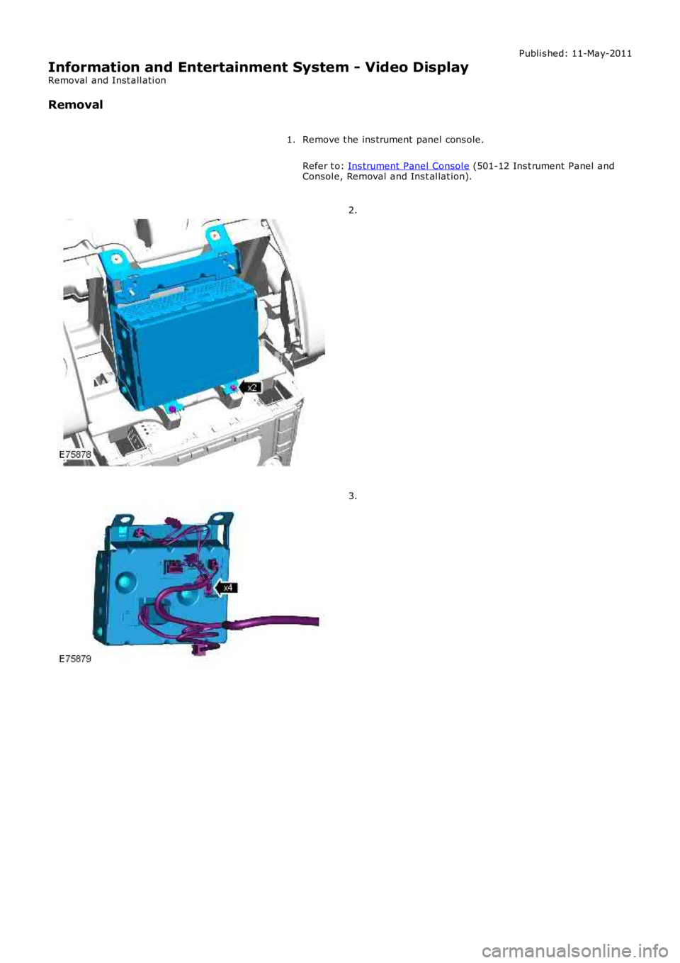
Remove t he ins trument panel cons ole.
Refer t o: Ins trument Panel Consol e (501-12 Ins t rument Panel andConsol e, Removal and Ins t al lat ion).
1.
2.
3.
Page 2318 of 3229
wi ll double lock the vehicle to dis engage the interior and ext erior handles , and will arm the active and pass ive ant i-t heftsystem. For additi onal informat ion, refer to:
Ant i-Theft - Active (419-01A Anti -Theft - Active, Des cri pti on and Operation),Ant i-Theft - Pass ive (419-01 Ant i-Theft - Pass ive, Description and Operat ion).
Central Locking System - Automatic Modes
The central locking s ys tem feat ures automat ic modes to control t he vehicl e entry points , and provi de prot ection for t hesystem components.
The central locking s ys tem incorporates the fol lowing automati c modes:
Misl ock modeSpeed dependant locking mode (i f programmed)Cras h unlocki ng modeRepeti tion bl ocking modeLockout protect ion modeAutomat ic relock mode (if programmed)Transport mode.
Mislock Mode
A mi slock occurs i f t he CJB receives an ext ernal lock or double lock reques t when a hi nged panel is ajar. To indicat e ami slock t he CJB sounds t he horns to produce a 100 milli second 'chirp'.
If a mi slock occurs due t o an external lock reques t when a hinged panel is ajar, t he CJB will not carry out a lock reques t onany acces s points .
Speed Dependant Locking Mode
W hen speed dependant l ocking is enabled the CJB wil l i nt ernal ly lock al l t he doors when t he vehicl e speed exceeds 8 km/h(5 mph) wit h al l the doors closed and the engine running. If the dri ver or front passenger door is opened and then cl os ed,when t he vehicl e s lows down or s tops and then increases to more t han 8 km/h (5 mph) again, the CJB wi ll int ernally lock thedoors.
Speed dependant locki ng may be enabled or dis abled by the deal er us ing the Land Rover approved diagnost ic syst em.
Crash Unlocking Mode
W ith the ignit ion in power mode 6 (Ignit ion), if a cras h occurs that tri ggers deployment of t he air bags , t hen t he CJB willunlock al l of t he doors . The CJB is informed of the crash by a s tatus mess age from the Rest raint s Cont rol Modul e (RCM) onthe medi um s peed CAN bus t hat changes from 'no crash' t o 'crash'.
The central locking s ys tem will als o perform crash unl ocking mode i f a 'no cras h' status mes sage is not received from t heRCM every 500 mi llis econds .For addit ional informat ion, refer t o: Ai r Bag and Safet y Belt Pretens ioner Supplement al Rest raint Sys tem (SRS) (501-20BSupplemental Res traint Sys tem, Des cription and Operat ion).
Repetition Blocking Mode
To prot ect the central locki ng s yst em motors and actuat ors against syst em mi s-use, the CJB i ncorporat es repeti tion bl ockingto limi t t he maximum operati ng rate of each mot or and actuator. The lock mot or in each door lat ch also i ncorporat es thermalprotect ion.
Central Locking System Motor and Actuator Operating ParametersMotor orActuatorCurrent On T ime(ms)Maximum Operations (perminute)Nominal Operating Current(A)Stall Current(A)Li ftgat e lat ch600 ± 10103.6 to 5.27.5Fuel fi ller door700 ± 1052.78Door doubl e l ock100 to 110100.281.14Door lock100 to 110100.543.31Lockout Protection Mode
The vehicle is not able to be locked us ing a front door central l ocking butt on or i ns trument panel central l ocking swit ch if anydoor is open.
If an internal lock reques t is recei ved from ei ther of the front door central locking but tons , t he CJB will cent rally lock thevehicle and then centrall y unl ock the vehicle if any door is open.
If a front door i s open and the open door central locki ng butt on i s press ed and held i n t he locked pos it ion, the open frontdoor may remai n i n the l ocked s tate. W hen t he open door is subs equently clos ed, the CJB will centrally unl ock all doors.
Automatic Relock Mode
Automati c rel ock prevent s accidental operation of the remote hands et but tons that will unlock and disarm t he vehicl e.
W hen the central locki ng s yst em is unlocked us ing the remote handset, and a door or l iftgate is not opened or t he remot ehandset is not placed in the s tart cont rol uni t wit hin 1 minut e, the CJB wi ll automatical ly lock or double l ock t he vehicl eagai n, depending on the previous ly locked mode.
Transport Mode
Al l new vehicl es are delivered from the factory in transport mode. Trans port mode replaces the t radit ional t ransi t rel ay andinhibits a number of el ectri cal s ys tems and features t o reduce quiescent drain from the batt ery during delivery. When t hevehicle is in t rans port mode 'trans p' is displayed in the i ns trument clust er odometer. Si ngle point ent ry is enabled and gl oballocki ng and unlocking usi ng t he remot e handset i s dis abled.
Page 2723 of 3229

Contents
3
R
Quick start
QUICK START ................................................... 7
Filling station information
FILLING STATION INFORMATION................... 33
Introduction
SYMBOLS GLOSSARY .................................... 35
LABEL LOCATIONS ......................................... 35
HEALTH AND SAFETY ..................................... 36
DATA RECORDING.......................................... 37
DISABILITY MODIFICATIONS ......................... 37
PARTS AND ACCESSORIES ............................ 37
Keys and remote controls
USING THE KEY .............................................. 40
GENERAL INFORMATION ON RADIO
FREQUENCIES ................................................ 40
USING THE REMOTE CONTROL ..................... 41
Locks
LOCKING AND UNLOCKING ............................ 44
Alarm
ARMING THE ALARM ..................................... 45
DISARMING THE ALARM ............................... 46
Seats
SITTING IN THE CORRECT POSITION ............ 47
MANUAL SEATS ............................................. 48
ELECTRIC SEATS ............................................ 49
HEAD RESTRAINTS ........................................ 51
REAR SEATS................................................... 51
HEATED SEATS............................................... 53
Seat belts
PRINCIPLE OF OPERATION ............................ 54
SEAT BELT REMINDER ................................... 55
FASTENING THE SEAT BELTS ........................ 56
SEAT BELT HEIGHT ADJUSTMENT................. 56
USING SEAT BELTS DURI NG PREGNANCY .... 57
Supplementary restraints system
PRINCIPLE OF OPERATION ............................ 58
AIRBAG WARNING LAMP ............................... 61
DISABLING THE PASSENGER AIRBAG ........... 62
AIRBAG SERVICE INFORMATION ................... 63
Child safety
CHILD SEATS ................................................. 64
BOOSTER CUSHIONS ..................................... 66
ISOFIX ANCHOR POINTS................................ 67
CHILD SAFETY LOCKS ................................... 69
Steering wheel
ADJUSTING THE STEERING WHEEL .............. 70
AUDIO CONTROL ........................................... 70
Lighting
LIGHTING CONTROL ...................................... 72
FRONT FOG LAMPS........................................ 72
REAR FOG LAMPS.......................................... 73
ADJUSTING THE HEADLAMPS....................... 73
HEADLAMP LEVELLING ................................. 73
HAZARD WARNING FLASHERS...................... 74
ADAPTIVE FRONT LIGHTING SYSTEM (AFS) . 74
DIRECTION INDICATORS ............................... 75
INTERIOR LAMPS .......................................... 76
APPROACH LAMPS ........................................ 76
CHANGING A BULB ........................................ 77
BULB SPECIFICATION CHART ........................ 86
Wipers and washers
WINDSCREEN WIPERS .................................. 87
RAIN SENSOR ................................................ 87
WINDSCREEN WASHERS............................... 88
HEADLAMP WASHERS................................... 88
REAR WINDOW WIPER AND WASHERS ........ 89
ADJUSTING THE WINDSCREEN WASHER JETS .
89
CHECKING THE WIPER BLADES .................... 90
CHANGING THE WIPER BLADES.................... 90
Windows and mirrors
ELECTRIC WINDOWS ..................................... 93
EXTERIOR MIRRORS ..................................... 94
ELECTRIC EXTERIOR MIRRORS .................... 95
INTERIOR MIRROR ........................................ 96
Instruments
INSTRUMENT PANEL OVERVIEW .................. 97
Information displays
TRIP COMPUTER ........................................... 99
INFORMATION MESSAGES ............................ 99