2006 LAND ROVER FRELANDER 2 seats
[x] Cancel search: seatsPage 172 of 3229
Check condit ion of batt ery.Check/top up bat tery electrolyte level .
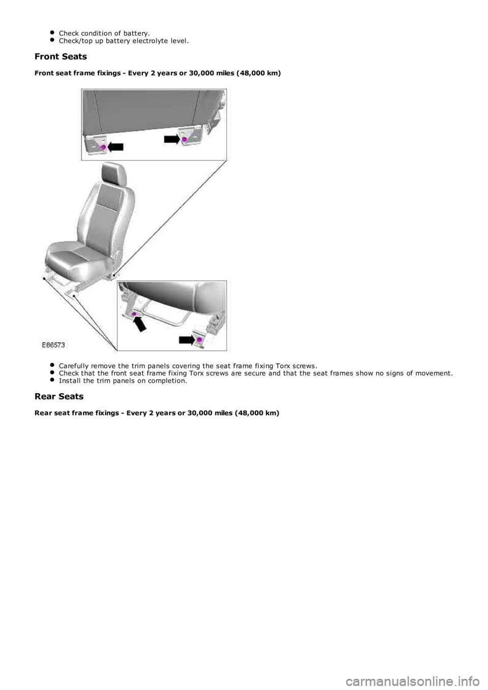
Front Seats
Front seat frame fixings - Every 2 years or 30,000 miles (48,000 km)
Careful ly remove t he trim panel s covering t he s eat frame fi xi ng Torx s crews .Check t hat the front s eat frame fixing Torx s crews are secure and that the seat frames s how no s i gns of movement .Ins t all the trim panel s on completi on.
Rear Seats
Rear seat frame fixings - Every 2 years or 30,000 miles (48,000 km)
Page 183 of 3229
Check condit ion of batt ery.
Check/top up bat tery electrolyte level .
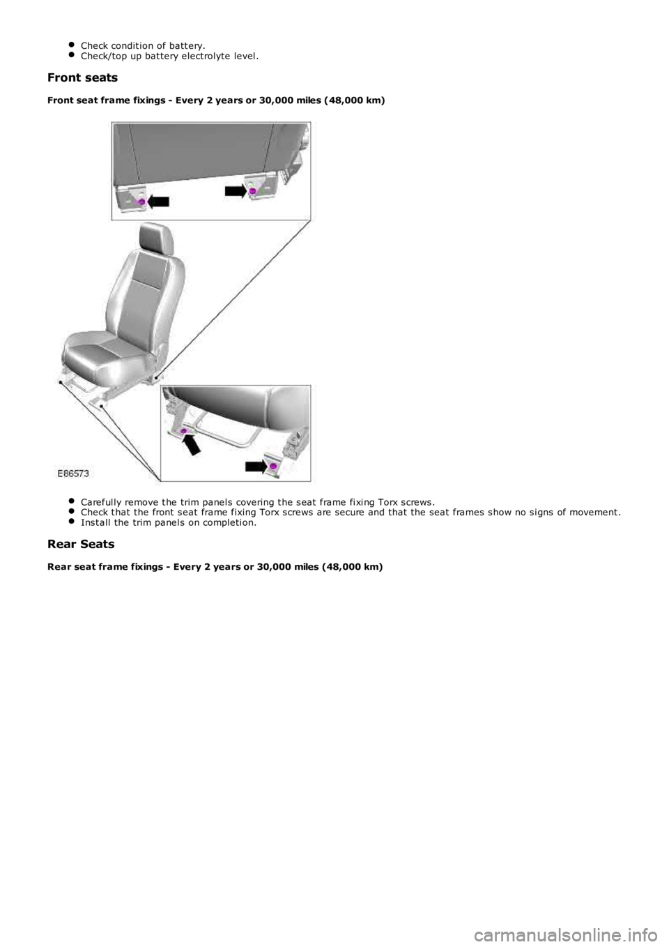
Front seats
Front seat frame fixings - Every 2 years or 30,000 miles (48,000 km) Careful ly remove t he trim panel s covering t he s eat frame fi xi ng Torx s crews .
Check t hat the front s eat frame fixing Torx s crews are secure and that the seat fram
es s how no s i gns of movement .Ins t all the trim panel s on completi on.
Rear Seats
Rear seat frame fixings - Every 2 years or 30,000 miles (48,000 km)
Page 2075 of 3229
Publi s hed: 11-May-2011
Multifunction Electronic Modules - Multifunction Electronic Module
Diagnosi s and Tes ti ng
Description and Operation
For a detail ed descripti on of the mult ifuncti on electronic cont rol modules , refer to the relevant Des cri pt ion and Operati on
s ect ion i n t he works hop manual .
REFER to: Module Cont roll ed Funct ions (419-10 Mult ifunct ion Elect ronic Modules , Descripti on and Operat ion).
Inspection and Verification CAUTION: Di agnos is by s ubs ti tut ion from a donor vehicle is
NO T acceptabl e. Subs ti tut ion of cont rol modules does
not guarant ee confirmat ion of a faul t, and may als o caus e addit ional fault s i n t he v ehi cl e being t est ed and/or t he donor
vehi cl e.
1. Verify t he cus t omer concern.
1.
2. Vis ually ins pect for obvious s igns of electrical damage.
2.
Visual Inspection Electrical
Fuse(s ) Electrical connect or(s )
W iri ng Harnes s
3.
If an obvious cause for an obs erved or report ed concern is found, correct t he caus e (if pos s ible) before
proceeding t o t he next s t ep.
3.
4. If t he caus e is not vis ually evi dent , check for Di agnos ti c Trouble Codes (DTCs) and refer t o t he DTC Index.
4.
DTC Index
• NOTE: If the control modul e is sus pect and t he vehicle remains under manufact urer warranty, refer to the W arrant y Poli cy
and Procedures manual (s ect ion B1.2), or determine i f any prior approval programme i s i n operat ion, prior t o t he
ins t al lat ion of a new modul e.
• NOTE: The DTC Index in t his s ecti on s hows informati on for DTCs t hat could be logge d in the Driver Door Modul e (DDM) or
Pass enger Door Module (PDM). For diagnosi s and t est ing i nformati on for: Dri ver Seat module.
REFER to: Seats (501-10 Seati ng, Diagnos is and Tes t ing).
Informat ion and Ent ert ai nment modul e.
REFER to: Informati on and Ent ert ainment Syst em (415-01 Informati on and Ent ert ainment Syst em, Diagnos is and Tes ti ng).
• NOTE: Generic scan t ool s may not read the codes li st ed, or may read only fi ve digi t codes . Mat ch the five di git s from t he
s can tool to the firs t fi ve di git s of the seven digi t code l is ted to ident ify t he fa ul t (t he las t t wo digi ts gi ve addi ti onal
informat ion read by the manufact urer approved diagnos t ic s ys tem).
• NOTE: W hen performing el ect ri cal volt age or resi s tance tes t s, al ways us e a digit al mult imet er (DMM) accurate to three
deci mal places , and wi th an up-to-date cali brat ion cert ificate. W hen t es ti ng res is t a nce, always take t he res i st ance of t he
DMM leads int o account.
• NOTE: Check and recti fy bas ic faul ts before beginni ng diagnos t ic rout ines i nvol vi n g pinpoint t es t s.
• NOTE: Ins pect connect ors for s igns of water ingres s , and pins for damage and/or co rros ion.
• NOTE: If DTCs are recorded and, aft er performi ng the pi npoi nt tes ts , a fault is no t present , an int ermi tt ent concern may
be t he caus e. Always check for loose connect ions and corroded terminals .
DT C Description Possible Cause Action
B108F23 Cabin Lock/Unl ock
Swi tch Signal s t uck low Carry out t he pinpoint t es t as s oci at ed wi th this DTC
us ing the manufact urer approved di agnos t ic s yst em
B109C15 Front Court es y Light Short to power or open circui t Refer to t he elect rical circuit di agrams and t est front
court esy li ght circui t for s hort t o power or open
ci rcuit
B109D11 Front Court es y Light Short to ground Refer to t he elect rical circuit di agrams and t est front
court esy li ght circui t for s hort ground
B10EB11 Driver door double
l ocking motor Short to ground Refer to t he elect rical circuit di agrams and t est
driver door double l ocking motor circui t for s hort
ground
B10EB15 Driver door double
l ocking motor Short to power or open circui t Refer to t he elect rical circuit di agrams and t est
driver door double l ocking motor circui t for s hort t o
power or open ci rcuit
B10EC11 Pas s enger door
double l ocki ng motor Short to ground Refer to t he elect rical circuit di agrams and t est
pas s enger door double locki ng motor circui t for s hort
ground
B10EC15 Pas s enger door
double l ocki ng motor Short to power or open circui t Refer to t he elect rical circuit di agrams and t est
pas s enger door double locki ng motor circui t for s hort
t o power or open ci rcuit
Page 2173 of 3229
Publi s hed: 11-May-2011
Seating - Seats
Des cript ion and Operat ion
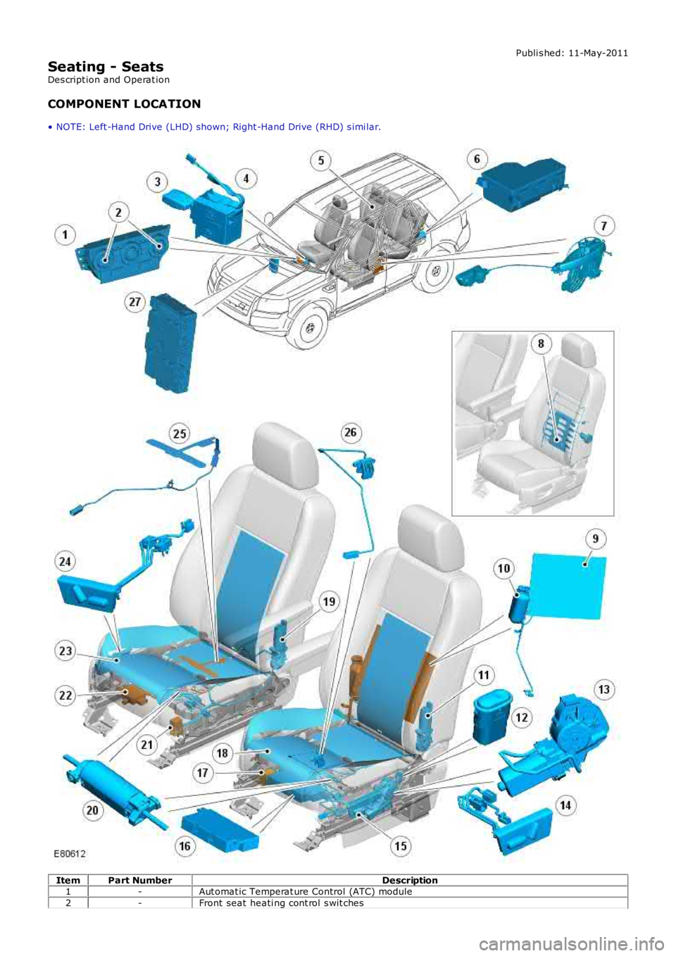
COMPONENT LOCATION
• NOTE: Left -Hand Drive (LHD) shown; Right -Hand Drive (RHD) s imi lar. Item
Part Number Description
1 -Aut omat ic Temperat ure Control (ATC) module
2 -Front seat heati ng cont rol s wit ches
Page 2174 of 3229
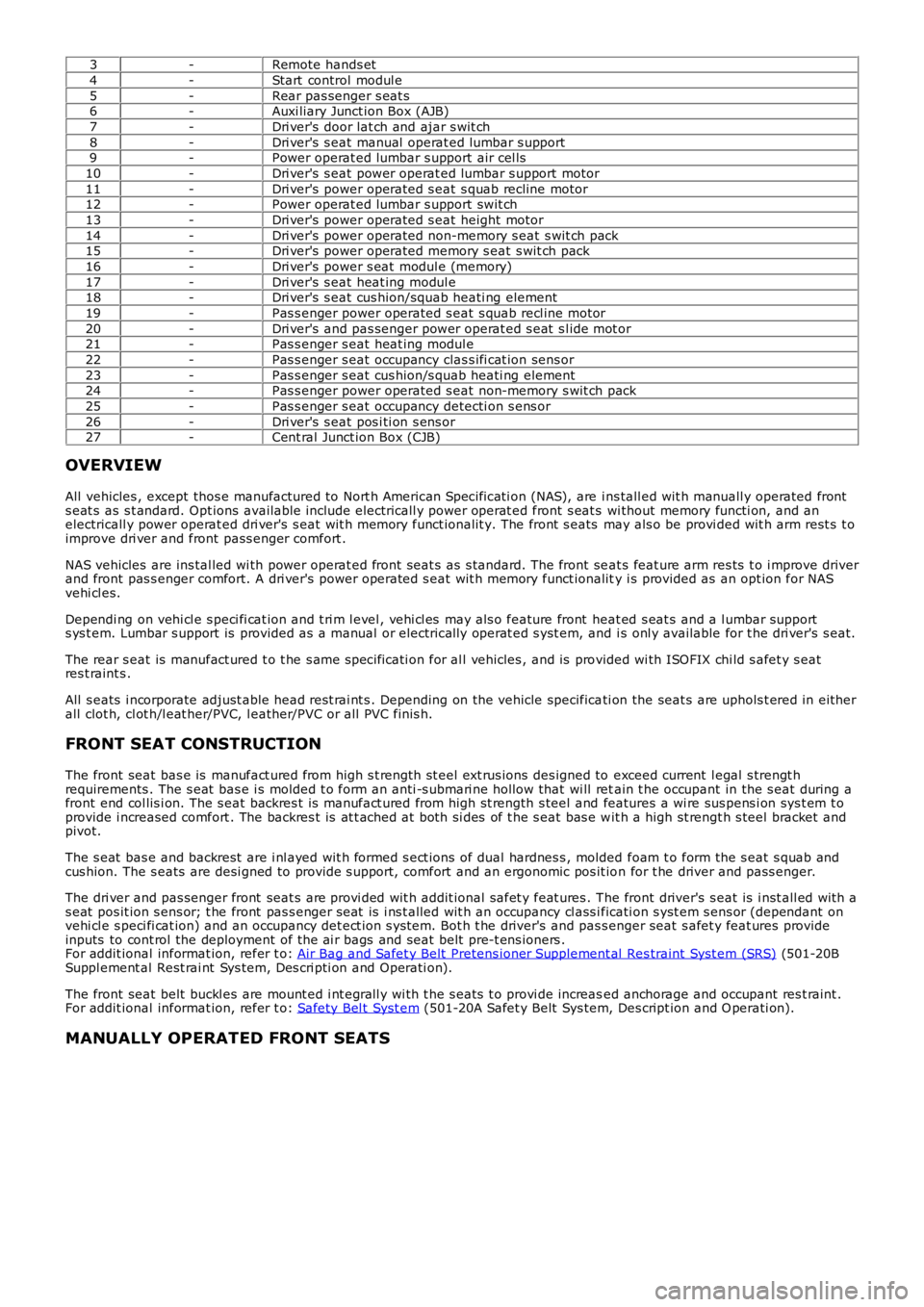
3
-Remote hands et
4 -Start control modul e
5 -Rear pas senger s eat s
6 -Auxi liary Junct ion Box (AJB)
7 -Dri ver's door lat ch and ajar s wit ch
8 -Dri ver's s eat manual operat ed lumbar s upport
9 -Power operat ed lumbar s upport air cel ls
10 -Dri ver's s eat power operat ed lumbar s upport motor
11 -Dri ver's power operated s eat s quab recline motor
12 -Power operat ed lumbar s upport swit ch
13 -Dri ver's power operated s eat height motor
14 -Dri ver's power operated non-memory s eat s wit ch pack
15 -Dri ver's power operated memory s eat s wit ch pack
16 -Dri ver's power s eat modul e (memory)
17 -Dri ver's s eat heat ing modul e
18 -Dri ver's s eat cus hion/squab heati ng element
19 -Pas s enger power operated s eat s quab recl ine motor
20 -Dri ver's and pas senger power operat ed s eat s l ide mot or
21 -Pas s enger s eat heat ing modul e
22 -Pas s enger s eat occupancy clas s ifi cat ion sens or
23 -Pas s enger s eat cus hion/s quab heati ng element
24 -Pas s enger power operated s eat non-memory s wit ch pack
25 -Pas s enger s eat occupancy detecti on s ens or
26 -Dri ver's s eat pos i ti on s ens or
27 -Cent ral Junct ion Box (CJB)
OVERVIEW
All vehicles , except thos e manufactured to Nort h American Specificati on (NAS), are i ns tall ed wit h manuall y operated front
s eat s as s t andard. Opt ions available include electricall y power operat ed front s eat s wi thout memory functi on, and an
electricall y power operat ed dri ver's s eat wit h memory funct ionalit y. The front s eats may als o be provi ded wit h arm rest s t o
improve dri ver and front pass enger comfort .
NAS vehicles are ins tal led wi th power operat ed front seat s as s tandard. The front se at s feat ure arm res ts t o i mprove driver
and front pas s enger comfort. A dri ver's power operated s eat wit h memory funct ionalit y i s provided as an opt ion for NAS
vehi cl es.
Dependi ng on vehi cl e s peci fi cat ion and t ri m l evel , vehi cl es may als o feature front h eat ed s eat s and a l umbar support
s ys t em. Lumbar s upport is provided as a manual or electrically operat ed s yst em, and i s onl y available for t he dri ver's s eat.
The rear s eat is manufact ured t o t he s ame s pecificati on for al l vehicles , and is pro vided wi th ISOFIX chi ld s afet y s eat
res t raint s .
All s eats i ncorporate adjust able head rest rai nt s . Depending on the vehicle specifica ti on the seat s are uphols t ered in eit her
all clot h, cl ot h/l eat her/PVC, l eather/PVC or all PVC finis h.
FRONT SEAT CONSTRUCTION
The front seat bas e is manufact ured from high s t rength st eel ext rus ions des igned to exceed current l egal s trengt h
requirements . The s eat bas e i s molded t o form an anti -s ubmari ne hollow that wi ll ret ain t he occupant in the s eat during a
front end col lis i on. The s eat backres t is manufact ured from high st rength s teel and features a wi re sus pens i on sys t em t o
provide i ncreased comfort . The backres t is at t ached at both si des of t he s eat bas e w it h a high st rengt h s teel bracket and
pivot.
The s eat bas e and backrest are i nl ayed wit h formed s ect ions of dual hardnes s , molded foam t o form the s eat s quab and
cus hion. The s eats are desi gned to provide s upport, comfort and an ergonomic pos it io n for t he driver and pass enger.
The dri ver and pas senger front seat s are provi ded wit h addit ional safet y feat ures . T he front driver's s eat is i nst all ed wit h a
s eat pos it ion s ens or; t he front pas s enger s eat is i ns t alled wit h an occupancy cl ass i ficati on s yst em s ens or (dependant on
vehi cl e s peci fi cat ion) and an occupancy det ect ion s ys tem. Bot h t he driver's and pas s enger seat s afet y feat ures provide
inputs to cont rol the deployment of the ai r bags and seat belt pre-t ens ioners .
For addit ional informat ion, refer t o: Air Bag and Safet y Belt Pretens ioner Supplement al Res traint Syst em (SRS) (501-20B
Suppl ement al Rest rai nt Sys tem, Des cri pti on and Operati on).
The front seat belt buckl es are mount ed i nt egrall y wi th t he s eats t o provi de increas ed anchorage and occupant res t raint .
For addit ional informat ion, refer t o: Safety Bel t Syst em (501-20A Safet y Belt Sys tem, Des cript ion and O perati on).
MANUALLY OPERATED FRONT SEATS
Page 2175 of 3229
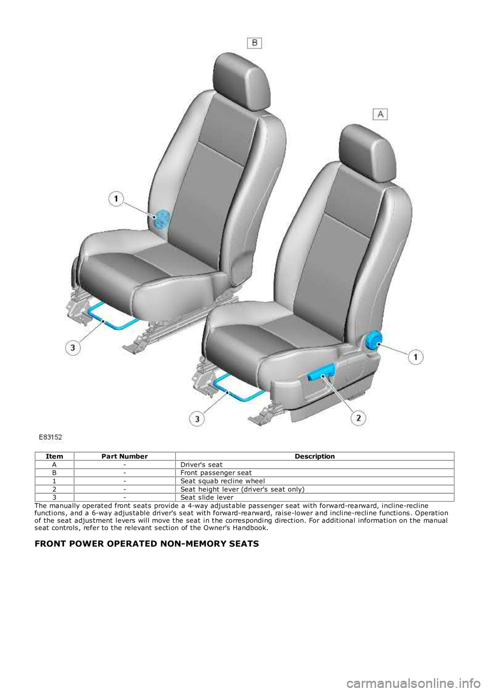
Item
Part Number Description
A -Driver's s eat
B -Front pas senger s eat
1 -Seat s quab recl ine wheel
2 -Seat height lever (dri ver's seat only)
3 -Seat s lide lever
The manually operat ed front s eat s provi de a 4-way adjust able pas s enger s eat wi th for ward-rearward, i ncl ine-recl ine
functi ons , and a 6-way adjus tabl e dri ver's s eat wit h forward-rearward, rai se-lower a nd incli ne-recli ne functi ons . Operat ion
of the seat adjus tment l evers wil l move t he seat i n t he corres pondi ng direct ion. For addit ional informati on on t he manual
s eat controls , refer to t he relevant s ecti on of the Owner's Handbook.
FRONT POWER OPERATED NON-MEMORY SEATS
Page 2181 of 3229
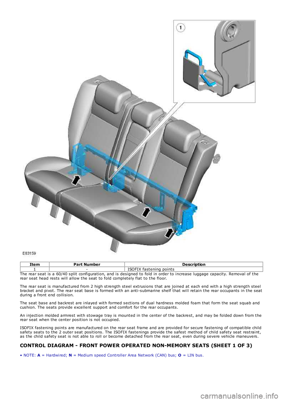
Item
Part Number Description
1 -ISOFIX fast ening point s
The rear s eat is a 60/40 s plit confi gurati on, and i s des igned to fold in order to i n crease luggage capaci ty. Removal of t he
rear s eat head res ts wi ll all ow t he s eat to fold compl et ely flat t o t he fl oor.
The rear s eat is manufact ured from 2 high s t rength st eel ext rus ions t hat are joined at each end wit h a hi gh st rengt h s teel
bracket and pi vot . The rear s eat bas e i s formed wi th an ant i-s ubmarine shelf t hat wi l l ret ai n t he rear occupants i n t he s eat
duri ng a front end col li si on.
The s eat bas e and backrest are i nl ayed wit h formed s ect ions of dual hardnes s mol ded foam that form the s eat s quab and
cus hion. The s eats provi de excell ent support and comfort for t he rear occupants .
An i nject ion molded armres t wit h s t owage tray is mount ed in the center of t he backre s t, and may be fol ded down from t he
rear s eat when the center pos it ion i s not occupi ed.
ISOFIX fast ening point s are manufact ured on the rear s eat frame and are provided for secure fas tening of compati ble chil d
s afety seat s t o the 2 outer s eat pos it ions . The ISOFIX fas t eni ngs provide t he s afes t method of chil d s afety seat res t rai nt ,
as t he chi ld s afet y s eat is not able to roll or become det ached from t he rear s eat , even during s evere vehicle maneuvers .
CONTROL DIAGRAM - FRONT POWER OPERATED NON-MEMORY SEATS (SHEET 1 OF 3)
• NOTE: A = Hardwi red; N = Medium s peed Cont roll er Area Net work (CAN) bus; O = LIN bus .
Page 2185 of 3229
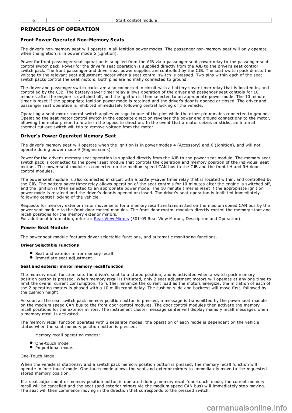
6
-St art control modul e
PRINCIPLES OF OPERATION
Front Power Operated Non-Memory Seats
The dri ver's non-memory s eat wil l operate i n all i gni ti on power modes . The pas senger non-memory seat wi ll only operat e
when t he ignit ion i s i n power mode 6 (Ignit ion).
Power for front pas s enger s eat operat ion is s upplied from t he AJB via a pas s enger s e at power relay t o t he pas s enger s eat
cont rol s wit ch pack. Power for t he driver's s eat operat ion is s upplied di rectl y from the AJB t o t he dri ver's s eat cont rol
s wit ch pack. The front pas s enger and dri ver s eat power suppli es are controlled by th e CJB. The s eat s wi tch pack direct s the
volt age to t he relevant s eat adjus tment mot or when a s eat control swit ch is pres s ed. Two pins wi thin each of t he s eat
s wit ch packs cont rol t he s eat motors. Bot h pins are normal ly connect ed to ground.
The dri ver and pas senger s wit ch packs are al s o connected i n circui t wit h a bat tery-s aver t imer relay t hat i s located in, and
cont rol led by t he CJB. The bat tery-s aver t imer relay all ows operati on of the driver and pas s enger s eat cont rols for 10
mi nut es aft er the engine is s wit ched off, and the i gni ti on is then s elected t o an ap propriat e power mode. The 10 minute
t imer is res et if t he appropriat e i gni ti on power mode is retai ned and the driver's d oor i s opened or clos ed. The driver and
pass enger s eat operati on is inhibit ed i mmediat el y fol lowi ng cent ral locking of t he v ehi cl e.
Operat ing a seat mot or control swit ch appli es volt age to one of t he pins whi le t he o t her pi n remai ns connect ed t o ground.
Operat ing t he s eat motor cont rol s wit ch in the oppos it e direct ion reverses the power and ground connecti ons to the mot or,
all owing t he mot or pi ni on t o rot ate in t he oppos i te di recti on. In t he event t hat a m ot or sei zes or s t icks , an i nternal
t hermal cut -out s wit ch wil l trip to remove volt age from t he mot or.
Driver's Power Operated Memory Seat
The dri ver's memory s eat wil l operat e when t he i gni ti on is in power modes 4 (Acces so ry) and 6 (Ignit ion), and wi ll not
operate during power mode 9 (Engine crank).
Power for the driver's memory s eat operat ion i s s uppl ied di rectl y from t he AJB t o t h e power s eat module. The memory s eat
s wit ch pack i s connected t o t he power seat module that cont rol s t he operati on and me mory pos it ion of t he i ndi vi dual s eat
mot ors . The power s eat module i s connected on the medi um s peed CAN bus t o t he CJB an d the front LH and RH door
cont rol modules .
The power seat module is als o connect ed in ci rcuit wi th a batt ery-saver ti mer rel ay that is locat ed wi thin, and controlled by
t he CJB. The batt ery-saver ti mer rel ay allows operat ion of t he s eat cont rols for 10 mi nut es aft er the engine is s wi tched off,
and t he ignit ion i s t hen sel ect ed to an appropri at e power mode. The 10 minut e t imer i s res et if t he appropri at e i gni ti on
power mode is retai ned and the driver's door i s opened or clos ed. The driver's s eat operat ion is i nhi bit ed immedi ately
fol lowing cent ral locki ng of the vehicl e.
Reques t s for memory exterior mirror movements for a memory recal l are t rans mit ted on the medi um s peed CAN bus by t he
power seat module to t he front door control modul es. The front door cont rol modules direct ly control the memory s t ore and
recall pos it ions for t he memory ext eri or mirrors.
For addit ional informat ion, refer t o: Rear Vi ew Mi rrors (501-09 Rear View Mirrors , Des cript ion and Operat ion).
Power Seat Mod ule
The power seat module features driver s electable funct ions , and aut omat ic monit ori ng functi ons .
Driver Selectable Functions
Seat and ext erior mirror memory recall Immediat e s eat adjus t ment.
Seat and exterior mirror memory recall function
The memory recall functi on s ets t he driver's seat t o a s t ored pos it ion, and is acti v at ed when a swi tch pack memory
posi ti on butt on is pres sed. W hen memory recal l i s i ni ti ated, only 2 seat adjus tment mot ors wil l operat e at any one t ime to
li mit the overall current cons umpti on. To furt her minimize t he current l oad as the m otors energize, the i nit iati on of each of
t he 2 operati ng mot ors i s phas ed wi th a 10 mill is econd del ay. The cushi on s lide and backres t wil l move fi rs t , foll owed by
t he cus hion height .
As s oon as t he seat s wit ch pack memory pos it ion but ton is pres s ed, a mes sage i s t ran s mit ted by the power s eat modul e
on t he medium s peed CAN bus to the front door control modul es. The door cont rol modu les t hen act ivat e t he memory
recall pos it ions for t he exteri or mirrors. The i nst rument clus t er mess age cent er wil l di s pl ay memory recall mes s ages when
a memory recall i s acti vat ed.
The memory recall functi on operates wit h 2 s eparate modes; t he operat ion of each mod e is dependant on t he vehicle
s tat us when the seat memory posi ti on butt on is pres sed.
Memory recall operati ng modes:
One-t ouch mode Proport ional mode.
One-Touch Mode
W hen t he vehicle i s s tat ionary and a s wit ch pack memory pos it ion butt on i s pres sed, t he memory recall functi on wil l
operate in 'one-touch' mode. One t ouch mode all ows the seat and exterior mirrors t o immediatel y move t o t he request ed
s tored memory pos i ti on.
If a s eat adjus t ment or memory pos it ion but ton i s operat ed during memory recal l 'one -t ouch' mode, t he current memory
recall wi ll be cancell ed and t he seat (and ext eri or mirrors via t he medium s peed CAN bus) wi ll i mmediat el y s top movi ng.
The s eat will t hen commence movi ng in the di recti on that corresponds to the press ed s wi tch.