2006 LAND ROVER FRELANDER 2 bonnet
[x] Cancel search: bonnetPage 42 of 3229
commencement of work.
Dis pos abl e heavy dut y plas ti c gloves s houl d be worn at all ti mes , and the affected area was hed down usi ng wire wool anda l imewat er (calcium hydroxi de) s olut ion t o neutrali se the acid before di spos ing of t he decompos ed Vit on res i due and fi nalcleaning of t he area. Aft er us e, t he plas ti c gloves should be dis carded carefull y and s afely.
Welding
W el di ng process es i ncl ude Res i st ance W elding (Spot W eldi ng), Arc W elding and Gas W eldi ng.
Resistance Welding
This proces s may cause parti cles of molt en met al to be emit ted at a high velocit y, and t he eyes and s ki n mus t beprot ect ed.
Arc Weld ing
This proces s emit s a hi gh level of ul tra-vi ol et radiat ion whi ch may caus e arc-eye and s ki n burns t o t he operator and t oother pers ons nearby. Gas -shi el ded welding proces s es are parti cul arly hazardous i n thi s res pect . Pers onal prot ecti on mus tbe worn, and s creens us ed to shi eld ot her people.
CONTACT LENS W EARERS ARE ADVISED TO REVERT TO ORDINARY SPECTACLES W HEN ARC W ELDING as t he arc spectrumis bel ieved to emit microwaves which dry out t he fluid bet ween t he lens and t he eye. This may res ult i n bli ndnes s whent he lens is removed from the eye.
Metal s patt er wil l al so occur, and appropri ate eye and skin prot ect ion i s neces s ary.
The heat of t he weldi ng arc wi ll produce fumes and gas es from the metals bei ng welded, the rods and from any appli edcoat ings or cont aminat ion on t he s urfaces being worked on. Thes e gas es and fumes may be toxic and inhalati on of thes es houl d be avoided. The us e of extract ion vent ilat ion t o remove the fumes from the working area may be neces s arypart icularl y in cas es where the general vent il ati on is poor, or where cons iderabl e weldi ng work i s anti ci pated. In ext remecas es or confined s paces where adequat e vent il ati on cannot be provided, air-fed res pirators may be neces s ary.
CAUTION: Some of t he components ins tal led t o t he vehi cl e e.g. t he int eri or cros s beam and underbonnet crossmember are manufact ured from magnesi um al loy. On no account s houl d any welding operat ions be at t empt ed on t hesecomponents .
Gas Welding (and Cutting)
Oxy-acet ylene t orches may be us ed for wel di ng and cutt ing, and s pecial care mus t be t aken to prevent l eakage of t hes egases , wit h consequent ri sk of fire and explos ion.
The process wil l produce met al spat ter and eye and s kin prot ecti on is necess ary.
The fl ame i s bri ght , and eye prot ect ion s hould be us ed, but t he ult ra-violet emi s si on is much les s than t hat from arcweldi ng, and l ighter filt ers may be us ed.
The process it sel f produces few t oxi c fumes , but s uch fumes and gases may be produced from coati ngs on the work,part icularl y duri ng cut ti ng away of damaged body parts , and inhalat ion of t he fumes s hould be avoided.
In brazing, toxic fumes may be produced from t he metal s in the brazi ng rod, and a s evere hazard may ari se if brazing rodscont aining cadmi um are used. In t hi s event parti cular care must be taken t o avoi d i nhalat ion of fumes and expert advi cemay be requi red.
SPECIAL PRECAUT IO NS MUST BE T AKEN BEFORE ANY WELDING OR CUT T ING T AKES PLACE ON VESSELS WHICHHAVE CO NT AINED COMBUST IBLE MAT ERIALS, FO R EXAMPLE BO ILING O R ST EAMING O UT OF FUEL T ANKS.
Warning Symbols on Vehicles
Decal s s howi ng warni ng s ymbol s wil l be found on various vehi cl e component s.
Thes e decals mus t not be removed. The warni ngs are for the at tent ion of owners /operat ors and persons carrying outs ervice or repair operat ions on t he vehicle.
Page 171 of 3229

Publi s hed: 11-May-2011
Maintenance Schedules - Maintenance Schedules - Gasoline Engines
Des cript ion and Operat ion
Under Bonnet View
ItemPart NumberDescription1-Coolant expans ion t ank
2-Brake flui d res ervoir (LH drive i llus t rated - RH dri ve on oppos i te si de)
3-Engine oi l fil ler cap4-Power s teeri ng res ervoir
5-Engine oi l l evel i ndi cat or
6-W indscreen washer fl uid res ervoi r
Maintenance Operations
CAUTION: Not e that t he 'A' and 'B' Service Interval s li s ted on the 'Maintenance Check Sheet' for vehicles operat ingunder arduous condi ti ons , vary from t hos e s pecifi ed for vehicles operat ing under normal condit ions . Reference mus tt herefore, always be made to the 'Arduous Condi ti ons secti on for vehicles operat ing under thes e condi ti ons .
Unles s s tat ed otherwis e, the foll owi ng operati ons mus t be carri ed out at every s ervice int erval.
Battery
Page 177 of 3229
For addit ional informat ion, refer t o: Parking Brake Cabl e Adjus tment (206-05 Parki ng Brake and Actuat ion, GeneralProcedures).
Door Locks and Hinges
1. Check operat ion of all door locks, bonnet lock and fuel fi ll er flap.
2. Lubricate al l door check s t raps , bonnet cat ch and fuel fill er fl ap cat ch.
Cooling System
CAUTION: Anti-freeze concentration must be maintained at 50%.
1. Check s peci fi c gravit y of cool ant us ing a hydrometer.
• NOTE: A s uit able hydromet er is avail abl e from the Equipment Programme under Part Number 511 3302 001 00.
2. Top-up cool ing s ys tem if neces s ary.For addit ional informat ion, refer t o: Specificati ons (303-03A Engine Cool ing - I6 3.2L Pet rol , Specificati ons ).
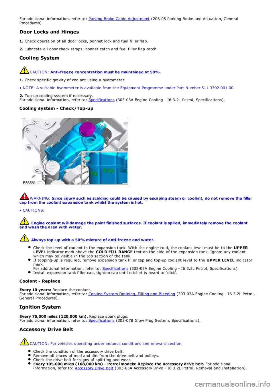
Cooling system - Check/Top-up
W ARNING: Since injury such as scalding could be caused by escaping steam or coolant, do not remove the fillercap from the coolant expansion tank whilst the system is hot.
• CAUTIO NS:
Engine coolant w ill damage the paint finished surfaces. If coolant is spilled, immediately remove the coolantand wash the area with water.
Always top-up with a 50% mixture of anti-freeze and water.
Check t he l evel of cool ant i n t he expans ion t ank. W it h t he engi ne col d, the coolant level must be to the UPPERLEVEL indicat or mark above the COLD FILL RANGE t ext on the s i de of the expans i on tank. Ignore any coolantwhich may be vis ible in t he t op s ect ion of t he t ank.If topping-up i s requi red, remove expans ion tank fill er cap and top-up coolant level to the UPPER LEVEL indicat ormark.For addit ional informat ion, refer t o: Specificati ons (303-03A Engine Cool ing - I6 3.2L Pet rol , Specificati ons ).Ins t all expans ion t ank fi ll er cap, ti ght en cap unti l ratchet is heard to 'cli ck'.
Coolant - Replace
Every 10 years: Repl ace the coolant.For addit ional informat ion, refer t o: Cool ing Sys tem Drai ning, Fi ll ing and Bl eeding (303-03A Engine Cooli ng - I6 3.2L Pet rol,General Procedures ).
Ignition System
Every 75,000 miles (120,000 km). Replace s park plugs .For addit ional informat ion, refer t o: Specificati ons (303-07B Glow Pl ug Sys t em, Specificati ons ).
Accessory Drive Belt
CAUTION: For vehi cl es operati ng under arduous condi ti ons s ee relevant s ecti on.
Check t he condi ti on of the access ory drive bel t.Remove all t races of mud and dirt from t he dri ve belt and pull eys .Check t he drive belt for si gns of s pli tt ing and wear.Every 105,000 miles (168,000 km) - Petrol models: Replace the accessory drive belt. For addi ti onalinformat ion, refer t o: Acces s ory Drive Belt (303-05A Acces s ory Drive - I6 3.2L Pet rol , Removal and Ins t allat ion).
Page 182 of 3229

Publi s hed: 11-May-2011
Maintenance Schedules - Maintenance Schedules - Diesel Engines
Des cript ion and Operat ion
Under Bonnet View Item
Part Number Description
1 -Coolant expans ion t ank
2 -Brake flui d res ervoir (RH drive i ll us t rat ed - LH dri ve on oppos i te si de)
3 -W indshi eld was her res ervoir
4 -Power s teeri ng fl uid reservoi r
5 -Engine oi l fil ler cap
6 -Engine oi l l evel i ndi cat or
Maintenance Operations CAUTION: Not e that t he A and B Services li st ed on t he Maint enance Check Sheet , appl i
cabl e t o vehi cl es operati ng
under arduous condi ti ons , vary bot h i n period and mil eage (kil ometres) t o t he int erv als s pecifi ed for t hose vehi cl es
operati ng under normal condit ions. Reference mus t therefore, always be made t o t he ' Arduous Condit ions s ect ion' for
vehi cl es operati ng under t hese condit ions .
Unles s s tat ed otherwis e, the foll owi ng operati ons mus t be carri ed out at every s ervi ce int erval.
Battery
Page 188 of 3229
For addit ional informat ion, refer t o: Parking Brake Cabl e Adjus tment (206-05 Parki ng Brake and Actuat ion, General
Procedures).
Door Locks and Hinges
1. Check operat ion of all door locks, bonnet lock and fuel fi ll er flap.
2. Lubricate al l door check s t raps , bonnet cat ch and fuel fill er fl ap cat ch.
Cooling System CAUTION:
Anti-freeze concentration must be maintained at 50%.
1. Check s peci fi c gravit y of cool ant us ing a hydrometer.
• NOTE: A s uit able hydromet er is avail abl e from the Equipment Programme under Part N umber 511 3302 001 00.
2. Top-up cool ing s ys tem if neces s ary.
For addit ional informat ion, refer t o: Specificati ons (303-03B Engine Cool ing - TD4 2.2L Dies el, Speci fi cat ions ).
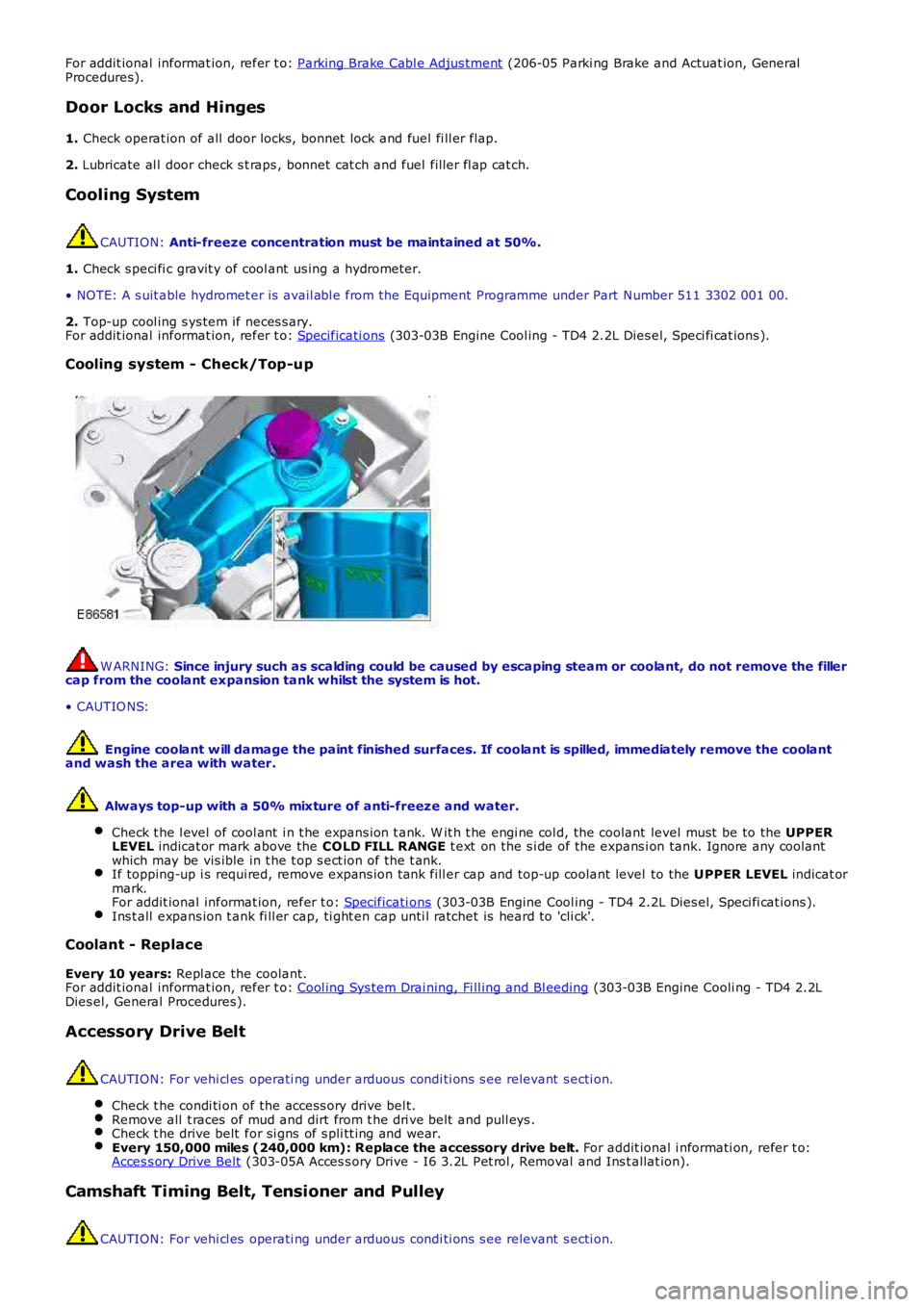
Cooling system - Check/Top-up W ARNING:
Since injury such as scalding could be caused by escaping steam or coolant, do not r emove the filler
cap from the coolant expansion tank whilst the system is hot.
• CAUTIO NS:
Engine coolant w ill damage the paint finished surfaces. If coolant is spilled, immed iately remove the coolant
and wash the area with water.
Always top-up with a 50% mixture of anti-freeze and water.
Check t he l evel of cool ant i n t he expans ion t ank. W it h t he engi ne col d, the coolant level must be to the UPPER
LEVEL indicat or mark above the COLD FILL RANGE t ext on the s i de of the expans i on tank. Ignore any coolant
which may be vis ible in t he t op s ect ion of t he t ank. If topping-up i s requi red, remove expans ion tank fill er cap and top-up coolant level
to the UPPER LEVEL indicat or
mark.
For addit ional informat ion, refer t o: Specificati ons (303-03B Engine Cool ing - TD4 2.2L Dies el, Speci fi cat ions ).
Ins t all expans ion t ank fi ll er cap, ti ght en cap unti l ratchet is heard to 'cli ck'.
Coolant - Replace
Every 10 years: Repl ace the coolant.
For addit ional informat ion, refer t o: Cool ing Sys tem Drai ning, Fi ll ing and Bl eeding (303-03B Engine Cooli ng - TD4 2.2L
Dies el, General Procedures).
Accessory Drive Belt CAUTION: For vehi cl es operati ng under arduous condi ti ons s ee relevant s ecti on.
Check t he condi ti on of the access ory drive bel t. Remove all t races of mud and dirt from t he dri ve belt and pull eys .
Check t he drive belt for si gns of s pli tt ing and wear.
Every 150,000 miles (240,000 km): Replace the accessory drive belt.
For addit ional i nformati on, refer t o:
Acces s ory Drive Belt (303-05A Acces s ory Drive - I6 3.2L Pet rol , Removal and Ins t allat ion).
Camshaft Timing Belt, Tensioner and Pulley
CAUTION: For vehi cl es operati ng under arduous condi ti ons s ee relevant s ecti on.
Page 1790 of 3229
This group of mess ages have a direct effect on the driving abi li ty and s afet y of t he vehi cl e, 'ENGINE SY STEM FAULT' forexampl e. Thi s mes s age woul d requi re an immedi at e react ion from the driver in res ponse t o t he mes s age. Pri ori ty 1mes s ages wi ll als o be accompani ed by t he appropriat e warni ng indicat or flas hing and a cont inuous chime from theins t rument clus ter. If more t han one priorit y 1 mes s age is present , each mes s age is di s pl ayed in t urn at 3 s econdint ervals .
Priority Group 2
This group of mess ages do not direct ly affect the driving abi lit y or s afet y of the vehicle, 'CHECK BRAKE PADS' for example.This mes s age mus t be noted by t he driver and the cause recti fi ed as s oon as pos s ibl e. Each of thes e mes s ages isdis played once when power mode 6 is ent ered or when t he faul t occurs for a predetermined t ime peri od. Thes e mes sagescan be recall ed by the driver by pres s ing t he t ri p res et butt on for more t han 3 s econds .
Priority Group 3
This group of mess ages rel at e t o l ow pri ori ty mes s ages , 'LOW W ASHER FLUID' for exampl e. Depending on the mes s age,s ome mes s ages are only s hown at t he end of a journey to avoid annoyance to t he driver. The mes s ages wi ll beaccompanied by a chi me when t he igni ti on is s wi tched off t o alert the driver to their presence.
MESSAGE LIST
Mes sages are dis played in a language appropriat e for t he market s peci fi cat ion of t he vehi cl e. The language can be changedif requi red us ing the Land Rover approved diagnos ti c sys t em.
• NOTE: The li s t bel ow i s s hown in al phabeti cal order.
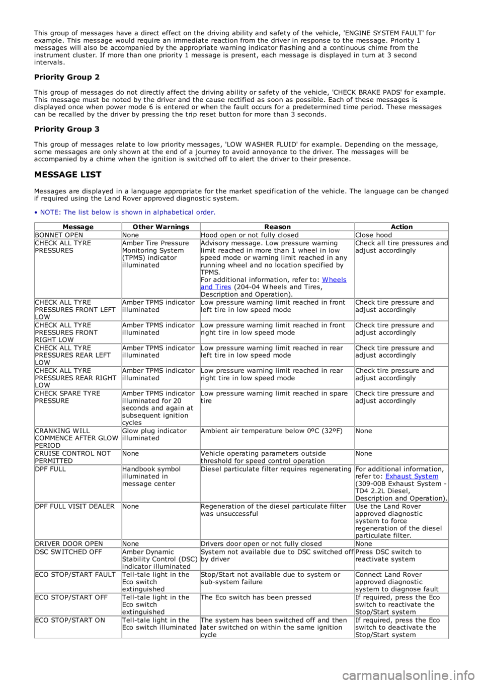
MessageO ther WarningsReasonAction
BONNET OPENNoneHood open or not fully cl osedCl ose hoodCHECK ALL TY REPRESSURESAmber Ti re Pres sureMonit oring Sys tem(TPMS) indi cat oril lumi nat ed
Advi sory mes s age. Low pres s ure warningli mit reached i n more than 1 wheel i n lows peed mode or warning l imi t reached in anyrunning wheel and no locati on s pecified byTPMS.For addit ional informati on, refer t o: W heelsand Tires (204-04 W heel s and Tires,Descripti on and Operat ion).
Check all t ire pres s ures andadjust accordingly
CHECK ALL TY REPRESSURES FRONT LEFTLOW
Amber TPMS indicatoril lumi nat edLow pres s ure warning l imi t reached in frontleft ti re i n l ow s peed modeCheck t ire pres s ure andadjust accordingly
CHECK ALL TY REPRESSURES FRONTRIGHT LOW
Amber TPMS indicatoril lumi nat edLow pres s ure warning l imi t reached in frontri ght t ire i n low s peed modeCheck t ire pres s ure andadjust accordingly
CHECK ALL TY REPRESSURES REAR LEFTLOW
Amber TPMS indicatoril lumi nat edLow pres s ure warning l imi t reached in rearleft ti re i n l ow s peed modeCheck t ire pres s ure andadjust accordingly
CHECK ALL TY REPRESSURES REAR RIGHTLOW
Amber TPMS indicatoril lumi nat edLow pres s ure warning l imi t reached in rearri ght t ire i n low s peed modeCheck t ire pres s ure andadjust accordingly
CHECK SPARE TY REPRESSUREAmber TPMS indicatoril lumi nat ed for 20s econds and agai n ats ubs equent i gni ti oncycles
Low pres s ure warning l imi t reached in s pareti reCheck t ire pres s ure andadjust accordingly
CRANKING W ILLCOMMENCE AFTER GLOWPERIOD
Glow pl ug indi cat oril lumi nat edAmbient air t emperature below 0ºC (32ºF)None
CRUISE CONTRO L NOTPERMITTEDNoneVehi cl e operat ing paramet ers out si dethreshold for s peed cont rol operati onNone
DPF FULLHandbook s ymbolil lumi nat ed inmes sage center
Dies el parti cul at e fil ter requi res regenerat ingFor addit ional i nformati on,refer t o: Exhaus t Sys t em(309-00B Exhaus t Sys tem -TD4 2.2L Di es el,Des cri pti on and Operati on).DPF FULL VISIT DEALERNoneRegenerat ion of t he dies el parti cul at e fil terwas unsucces s fulUse the Land Roverapproved di agnos ti csys tem t o forceregenerati on of the di es elparti cul at e fil ter.
DRIVER DOOR OPENNoneDri vers door open or not ful ly clos edNone
DSC SW ITCHED OFFAmber Dynami cStabil it y Control (DSC)indicator i lluminated
Sys t em not avai lable due to DSC s wit ched offby dri verPress DSC s wit ch toreact ivat e s ys t em
ECO STOP/START FAULTTel l-tal e li ght in t heEco swi tchext inguis hed
Stop/St art not avai lable due to sys tem ors ub-s ys t em failureConnect Land Roverapproved di agnos ti csys tem t o diagnos e fault
ECO STOP/START O FFTel l-tal e li ght in t heEco swi tchext inguis hed
The Eco swi tch has been pres s edIf requi red, pres s the Ecoswi tch t o react ivate theSt op/St art s yst em
ECO STOP/START O NTel l-tal e li ght in t heEco swi tch i ll uminatedThe s ys t em has been s wit ched off and thenlat er s wi tched on wi thin the same ignit ioncycle
If requi red, pres s the Ecoswi tch t o deact ivat e t heSt op/St art s yst em
Page 1923 of 3229

vent il ati on of the headlamp whi le prevent ing t he i ngress of wat er.
The headl amps can be quickl y removed for bul b repl acement due t o t he uni que 'Rail Lock' s yst em. Headl amp acces srequires t he removal of 2 bol ts securi ng the headlamp to the bonnet cl osi ng panel . A l ocking l ever at t he rear of theheadl amp can t hen be li ft ed, releasi ng a l ocking tab at t he base of the headlamp body. The headl amp can then be pul ledforward on the rail and, aft er di sconnect ion of t he harness connect or, removed from t he vehi cl e. The 'Rail Lock' s ys t emensures that t he headl amp ali gnment i s not compromis ed duri ng t he removal proces s .
Each headlamp has two access covers at t he rear. The larger cover requi res t he l ocking l ever t o be released from i ts gui des lot s to allow acces s to the cover. The cover can t hen be removed by rel easi ng 2 t abs to al low the hi gh and low beambulbs t o be changed. The circular rubber cover i s a pus h fi t onto t he rear of t he lamp ass embly. Removal of t he cover givesacces s t o the si de lamp and turn s ignal indicator bulbs .
On NAS vehicl es , t he s ide l amp is col ored orange. The s ide l amp lens i s desi gned so that li ght from t he s ide l amp bulbals o i ll uminates t he orange colored reflect or area at t he s ide of t he lamp wit hout the need for an addit ional bulb.
Halogen Headlamps
Page 1989 of 3229
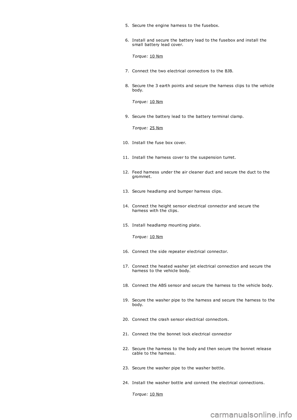
Secure t he engi ne harnes s to the fus ebox.
5.
Inst all and s ecure t he bat t ery l ead to t he fusebox and ins t al l the
s mall bat tery lead cover.
T orque: 10 Nm 6.
Connect t he two electrical connect ors t o t he BJB.
7.
Secure t he 3 eart h point s and s ecure t he harness cl ips t o t he vehi cl e
body.
T orque: 10 Nm 8.
Secure t he batt ery l ead to the bat tery terminal clamp.
T orque: 25 Nm 9.
Inst all t he fus e box cover.
10.
Inst all t he harness cover to the s us pens ion turret.
11.
Feed harness under t he air cleaner duct and s ecure the duct t o the
grommet.
12.
Secure headl amp and bumper harness cl ips .
13.
Connect t he height sens or elect rical connect or and s ecure t he
harnes s wit h t he cli ps .
14.
Inst all headl amp mount ing plat e.
T orque: 10 Nm 15.
Connect t he s ide repeat er el ect ri cal connector.
16.
Connect t he heat ed was her jet electrical connect ion and s ecure t he
harnes s t o the vehicl e body.
17.
Connect t he ABS s ens or and s ecure t he harness to t he vehicle body.
18.
Secure t he was her pipe to the harnes s and s ecure t he harness to the
body.
19.
Connect t he cras h s ens or electrical connect ors .
20.
Connect t he the bonnet lock electrical connect or
21.
Secure t he harness to the body and t hen secure the bonnet releas e
cabl e t o t he harness .
22.
Secure t he was her pipe to the was her bot tl e.
23.
Inst all t he washer bott le and connect t he elect rical connecti ons .
T orque: 10 Nm 24.