2006 LAND ROVER FRELANDER 2 check oil
[x] Cancel search: check oilPage 14 of 3229
Publi s hed: 11-May-2011
General Information - Standard Workshop Practices
Des cript ion and Operat ion
Vehicle in Workshop
W hen working on a vehicl e in the workshop al ways make sure t hat :
W here practi cable, t he parking brake is appli ed and t he wheel s are securely chocked to prevent t he vehi cl e movingforwards or backwards .W henever pos si ble, t he ignit ion key i s removed before any work is carried out on t he vehi cle.If the engine i s t o be run, t here i s adequat e vent il ati on, or an extract ion hos e i s us ed to remove exhaus t fumes.There i s adequat e room to rais e the vehicle and remove t he wheel s , if neces s ary.Fender covers are al ways ins tal led i f any work i s to be carri ed out in t he engine compart ment.W here practi cable, t he batt ery i s dis connected if worki ng on the engi ne, underneath t he vehicle, or if t he vehi cl e i srai sed.
• CAUTIO NS:
Prior to dis connect ing the bat tery, refer to the El ect ri cal Secti on of this manual - Bat tery dis connect ion/connect ion.For addit ional informat ion, refer t o: Specificati ons (414-01 Bat t ery, Mount ing and Cables , Speci ficat ions).
W hen el ect ri c arc wel ding on a vehi cl e, al ways dis connect t he generator wi ri ng to prevent t he pos si bili ty of a s urgeof current caus i ng damage to the i nternal component s of the generat or.
If us i ng welding equipment on t he vehicle, a s uit abl e fire exti nguis her is readily avail able.
Battery - General
• CAUTIO NS:
Prior to carrying out any procedures which i nvol ve dis connect ing/ or connecti ng the bat tery, refer t o t he ElectricalSect ion of t his manual - Batt ery di sconnect ion/connect ion.For addit ional informat ion, refer t o: Specificati ons (414-01 Bat t ery, Mount ing and Cables , Speci ficat ions).
A di s charged bat tery condit ion may have been caus ed by an electrical short ci rcuit . If t his condit ion exis t s there wil lbe an apparentl y li ve circuit on the vehicle even when al l normal circuit s are s wit ched off. This can cause arcing when t hejumper cables are connect ed.
W hi le it i s not recommended that the vehicl e is jump s t art ed, i t is recognized t hat thi s may occas ionall y be t he onl ypracti cal way t o mobi lize a vehi cl e. Prior t o at tempt ing a jump s t art , reference must be made to the El ect ri cal Secti on oft hi s manual - Jump St art ing.
Followi ng jump s tart ing of a dis abl ed vehi cle, the di s charged bat tery mus t be checked for s erviceabili ty and recharged offt he vehi cl e as s oon as poss ibl e t o avoi d permanent damage.
Do not rel y on t he generator t o res t ore a di s charged bat tery. For a generat or t o recharge a batt ery, it woul d take i n exces sof eight hours cont inuous dri vi ng wi th no addi ti onal loads placed on t he batt ery.
Always make s ure that t he jumper cabl es are adequate for the tas k.Always make s ure that t he s lave batt ery i s of the same vol tage as t he vehicle bat tery. The bat teries mus t beconnected i n paral lel.Always make s ure that s wit chabl e electric circui ts are s wi tched off before connecti ng jumper cabl es. This reducest he ri sk of arci ng occurring when the final connecti on is made.
Towing the Vehicle
W ARNING: W hen t owing i s neces sary, reference mus t be made to the Jacki ng, Lift ing and Towing Secti on of thi sManual .
W hen t he vehicle i s being t owed dock the remote cont rol and s wit ch on the ignit ion. (s t eering l ock releas ed and warni ngli ght s i ll uminated). Onl y t hen wil l the s t eering, turn s ignal lamps , horn and s t op lamps be operat ional. Fail ure t o followt hes e i nst ructi ons may res ult in pers onal injury. It mus t be noted that wit h t he engine not running, t he power s t eering andbrake boost er wil l be inoperat ive t herefore, great er effort wil l be needed t o s t eer t he vehicle and apply the brakes .
General Installation Instructions
Component removal
W henever pos si ble, clean component s and the surroundi ng area before removal .
Blank off openings expos ed by component removal .Followi ng dis connecti on, s eal fuel, oil or hydrauli c li nes i mmediat ely us ing sui table bl anki ng plugs or caps .Seal open ends of expos ed oil ways us i ng sui table tapered hardwood pl ugs or cons pi cuous pl as t ic pl ugs .Immediat el y a component i s removed, place it i n a sui table contai ner; us e a s eparate cont ai ner for each componentand it s as s ociat ed part s .
Page 15 of 3229
Clean bench and provide marking mat eri al s , labels and containers before di s as s embli ng components .
Disassembling
Obs erve s crupul ous cl eanl ines s when dis as sembl ing component s, parti cul arly when brake, fuel, air s us pens ion or hydrauli cs ys t em parts are dis as sembl ed. A part icle of dirt or cloth fragment could caus e a s eri ous malfunct ion i f trapped i n t hes es ys t ems .
Blow out al l tapped holes , crevi ces , oil ways and flui d pass ages wit h dry, compres s ed air.
W ARNING: Sui table eye protecti on mus t be worn.
Us e s uit abl e marker i nk to identi fy mat ing parts , do not us e a s cri ber or cent re punch as t hey coul d ini ti at e cracksor dis torti on.W i re or t ape mat ing part s t oget her where neces s ary t o prevent acci dent al i nterchange.Suit abl y identi fy parts which are to be renewed and t o thos e part s requi ri ng further ins pect ion. Keep thes e part ss eparate.To make s ure that t he correct replacement part has been obt ained, do not dis card a part due for renewal unt il aftercomparing i t wit h t he new part.
Cleaning Components
Always us e cleaning agents whi ch are s uit able for the work being undert aken and the component s being cleaned. NEVERus e gasol ine (pet rol ) as a cleaning agent (degreas er). Always make s ure that the component bei ng cleaned is compati blewit h t he cleaning agent.
Always follow the manufact urer's i ns t ructi ons regarding the us e of cleaning agents and make sure t hat t he envi ronment inwhich t he work is being undert aken is s uit able. See Healt h and Safet y Precaut ions for furt her informati on regardi ngcleaning.
General Inspection of Components
All component s s houl d be i ns pect ed for wear or damage before reas s embl ing.
Always make s ure that component t o be i ns pected i s clean and free from oil or greas e.W hen a component is t o be checked di mensi onal ly agains t desi gn s pecified values , use the appropriat e meas uringequi pment i.e. micromet ers , verniers, s urface plates , dial t es t i ndi cat ors (DTI).Always make s ure that all meas uri ng equi pment is correct ly cali brat ed before us e.Reject a component which i s not wit hin specified values /l imi ts or i f it appears t o be damaged.A component may be rei ns t alled if dimens ions obt ai ned during checki ng are at t he maximum t olerance l imi t and itis in an undamaged condi ti on.Bearing journal clearances should be checked where neces s ary us ing Pl ast igauge.
Joints and Joint Faces
All gas ket s s houl d be i ns t alled dry unles s s tat ed otherwis e. Always appl y t he s pecified l ubricant to O-rings and i nst allO-ri ngs us ing the fingers onl y.
Us e gasket removal s pray and/or plas t ic s crapers t o remove traces of old gas ket.
CAUTION: DO NOT us e met al s crapers or emery clot h as t hes e may damage the s eali ng s urfaces.
Many joi nts us e s ealants ins tead of gasket s as t he seal ing medium. W here t his is t he cas e, t he s eal ant t oget her wit h i tspart number wil l be found l is ted i n t he rel evant repair operat ion and al so in the s ealants table.
CAUTION: Always remove all t races of the ol d s eal ant prior t o reas s embly. Use plas tic s crapers, s pecifi ed s olvent swhere avail abl e or dry, l int free clot h. DO NOT us e met al scrapers or emery clot h as t hese may damage the seali ngs urfaces . Make sure t hat s eali ng s urfaces are free from oi l or greas e as sealant s wil l not adhere properly to contaminateds urfaces .
Do not all ow s ealant to ent er tapped holes or oil ways .
Locking Devices
Always repl ace locki ng devi ces wit h one of the s ame des ign and of t he correct s ize.
Tab washers
Always release locki ng t abs before l oos ening fixings , do not reus e t ab washers.
Locknuts
Always us e a backing s panner when l oos ening and t ighteni ng locknut s, brake and fuel pipe unions .
Roll pins
Always i ns t all new roll pins of t he correct s ize.
Circlips
Always i ns t all new circl ips ens uri ng that t hey are of t he correct s ize for t he groove.
Page 16 of 3229
Woodruff keys
W oodruff keys may be reus ed provided t here i s no i ndi cat ion of wear or dis torti on.
Remove any burrs from edges of keyways us ing a fine fil e.
Split pins
Never at tempt t o s t raight en and reus e a s pli t pin, always make s ure that repl acement pins are of the correct si ze for t hehole i n which t hey are to be ins tal led.
Screw Threads
Damaged nuts , bolt s and s crews mus t always be dis carded. Att empti ng to recut or repai r damaged threads wi th at ap or di e i mpai rs the s t rength and fi t of t he t hreads and is not recommended.
• NOTE: Duri ng cert ai n repai r operat ions , it may be neces sary t o remove t races of t hread locking agent s us ing a tap.W here thi s is neces sary, t he i ns t ructi on to do s o wi ll appear in the relevant operation and it i s ess enti al that a t ap of thecorrect s ize and t hread i s used.
Some bolt s are coat ed wit h a thread locki ng agent and unles s s tat ed otherwis e, they mus t not be reus ed. Newbolt s havi ng the same part number as the original mus t always be i nst all ed. W hen nuts or bolt s are to bedis carded, t he repai r operat ion and relevant torque chart will i ncl ude an ins truct ion to that effect . Do not usepropri etary thread locki ng agent s as t hey may not meet the specificati on required. See al so Encapsul at ed('Patched') Bol ts and Screws.Always make s ure that repl acement nuts and bol ts are at leas t equal i n s trengt h t o thos e t hat they are repl acing.Cast ell ated nut s mus t not be loosened t o accept a s pli t pin except in recommended cas es when thi s forms part ofan adjus tment .Do not all ow oil or greas e t o enter bli nd holes , the hydrauli c acti on res ult ing from ti ght ening t he bolt or s tud cans plit t he housi ng and als o gi ve a fal s e torque reading.Always t ighten a nut, bolt or s crew to t he s peci fi ed torque fi gure, damaged or corroded threads can give a fals et orque reading.Nut and bolt loos ening and t ightening sequences , where gi ven, mus t ALW AY S be foll owed. Di st ort ion ofcomponents or fault y s eal ing of joints wil l res ul t if t he s equences are not fol lowed. W here an ins t ructi on is gi ven tot ighten i n s tages , thes e s tages mus t be adhered t o; do not at t empt to combi ne st ages part icul arl y where cert ains tages involve t ight eni ng by degrees.To check or re-t ighten a fi xing t o a s peci fi ed t orque, firs t loosen a quart er of a turn, t hen ret ighten to the s peci fi edt orque fi gure.Unles s ins t ructed ot herwis e, do not lubricat e bolt or nut t hreads pri or t o i nst all ing.
W here it i s s tat ed t hat bolt s and s crews may be reus ed, t he fol lowi ng procedures must be carri ed out:
Check t hat threads are undamaged.Remove all t races of locki ng agent from the threads .
CAUTION: DO NOT us e a wi re brus h; take care t hat threads are not damaged.
Make s ure t hat threads are clean and free from oil or greas e.Apply t he s pecified locki ng agent t o t he bolt t hreads .
Bolt and Nut Identification
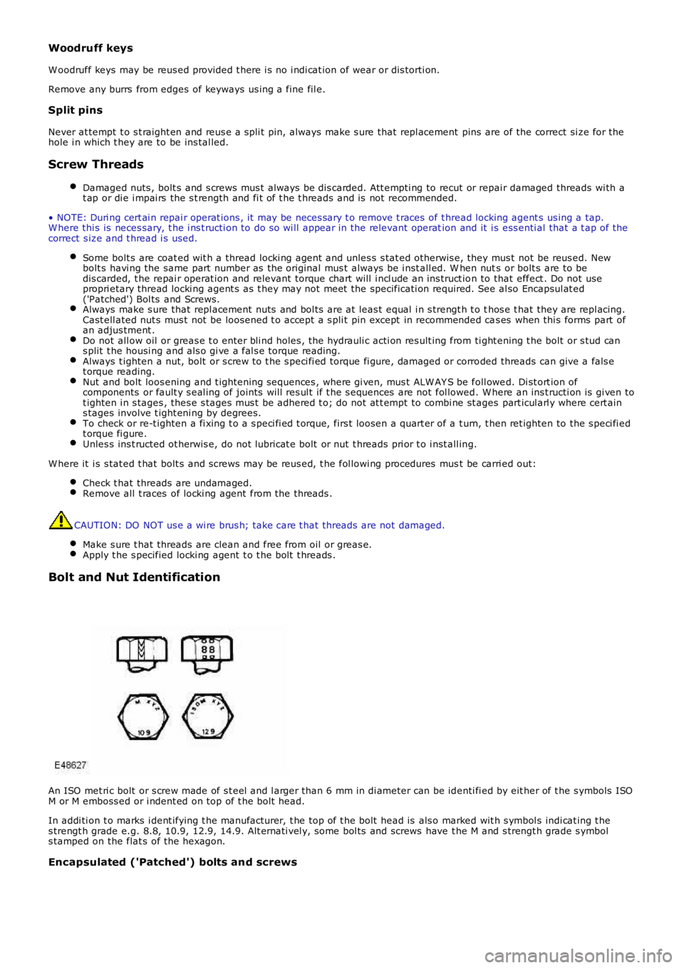
An ISO met ri c bolt or s crew made of s t eel and l arger than 6 mm in di ameter can be identi fi ed by eit her of t he s ymbols ISOM or M emboss ed or i ndent ed on top of t he bolt head.
In addi ti on t o marks i dent ifying t he manufacturer, t he top of t he bolt head is als o marked wit h s ymbol s indi cat ing t hes trengt h grade e.g. 8.8, 10.9, 12.9, 14.9. Alt ernati vel y, some bol ts and screws have t he M and s trengt h grade s ymbols tamped on the flat s of the hexagon.
Encapsulated ('Patched') bolts and screws
Page 18 of 3229
A clock face sys tem is somet imes us ed as an al ternat ive method of indi cat ing t he s trengt h grade. The external chamfers ora face of t he nut is marked i n a pos it ion relati ve to the appropriat e hour mark on a cl ock face to indicate the s t rengthgrade.
A dot i s used to l ocat e t he 12 o'clock posi ti on and a das h t o indi cat e t he st rengt h grade. If t he grade i s above 12, t wodots i dent ify t he 12 o'clock posi ti on.
W hen t ight eni ng a s lot ted or cas tell ated nut , never loos en it t o i nsert a s pli t pi n except where s pecified as part of anadjus tment procedure. If di fficult y is experi enced i n correct ly pos it ioning t he s lot, alt ernati ve washers or nut s s houl d bes elect ed.
W here a nut is ti ght ened to adjust or mai ntain bearing pre-l oad, t he ti ght ening procedure must be adhered to.
Self-locking nuts
Unles s s tat ed otherwis e, sel f-locki ng nuts once removed must be di s carded and new nut s of t he s ame t ype and st rengthgrade i nst all ed.
Ball and Roller Bearings
W hen removing and i ns t alli ng bearings , make s ure t hat the foll owing pract ices are obs erved t o make s ure components erviceabi li ty:
CAUTION: Service t ools have been devel oped for removing the majori ty of beari ngs ; t hes e must al ways be usedwhere specified.
Remove all t races from beari ng under i ns pecti on by cl eani ng wit h a sui table degreas ant; maintai n absol ut ecleanlines s t hroughout operati ons.Conduct a vis ual ins pect ion for markings on roll ing element s , raceways , out er s urfaces of outer or inner surfaces ofinner ri ngs . Reject any bearings found to be marked s ince marking i n thes e areas i ndicat es ons et of wear.Hold inner race of bearing between finger and t humb of one hand and rotat e outer race to check that it revol vesabsol ut ely smoot hly. Repeat holding out er race and rot ati ng inner race. DO NOT spi n t he bearing.Rotat e outer ring gentl y us ing a reci procati ng movement whi ls t holding i nner ring; feel for any check or obs truct iont o rot ati on. Reject beari ng if movement is not abs ol utel y s moot h.Check beari ng for bl uei ng or si gns of overheat ing.Lubricate bearing wi th the s pecifi ed lubricant .Ins pect bearing s urface of s haft and beari ng hous i ng for dis colorat ion or ot her markings which i ndi cat e overheati ngof bearing or movement between beari ng and s eat ing.Before ins tal li ng bearing, make s ure t hat shaft and bearing hous ing are cl ean and free from burrs .If one bearing of a pair s hows s igns of wear, overheati ng etc., i t is advis able to replace bearings as a pai r unl ess itis sus pect ed t hat one beari ng may have been fault y when i nst all ed, was i nst all ed incorrect ly or t he faul t aros e duet o oil s eal fail ure.Never reins tal l a bearing unles s i t is i n a full y s erviceabl e condi ti on.
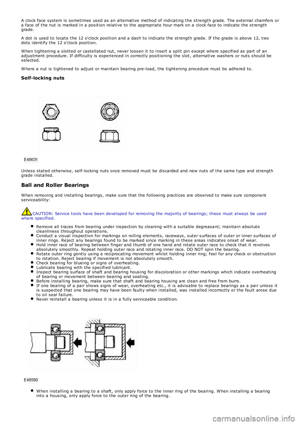
W hen i nst all ing a bearing t o a s haft , only apply force t o t he inner ri ng of the beari ng. W hen ins t al li ng a beari ngint o a hous ing, onl y apply force t o t he out er ri ng of the bearing.
Page 19 of 3229
CAUTION: Service t ools have been devel oped for ins tal ling the majori ty of beari ngs ; t hese must al ways be usedwhere specified.
In the cas e of greas e l ubricated beari ngs , fil l t he s pace bet ween t he bearing and out er s eal wit h t he recommendedgrade of greas e before ins t al li ng the seal.
CAUTION: W hen a waxed oil s eal (ins tal led dry) t ype of oil s eal i s to be ins t al led, take great care that greas e doesnot cont aminate the runni ng s urface of t he s eal .
Always make s uit able reference marks bet ween t he components of s eparable bearings e.g. t aper roller beari ngswhen dis as sembl ing t o make s ure correct locati on of components when as s embli ng. Never ins tall new roll ers i n anouter ring, al ways ins tal l a new beari ng ass embly.
Brake Pads and Linings
Always i ns t all t he correct grade and s peci fi cat ion of brake pads and li nings . W hen repl acing thes e it ems , always repl ace ascomplete axl e s ets .
Brake Hydraulics
Always obs erve t he fol lowing recommendat ions when worki ng on t he braking s ys tem:
W ARNING: Do not int ermi x brake fluid of di fferent specificati ons .
Always us e t wo s panners when loos eni ng or ti ght ening brake pi pes or hos e connect ions.Make s ure t hat hos es run in a natural curve and are not kinked or twi st ed.Ins t all brake pipes and hos es s ecurel y in their retaini ng clips and make sure t hat they cannot cont act a pot enti alchafing point .Containers used for brake fluid must be kept abs ol utel y cl ean.Do not s tore brake fluid in uns ealed containers, t he fluid will abs orb wat er which wi ll lower t he boili ng point of thefl uid.Do not all ow brake flui d to be cont aminat ed wit h ot her fluids such as mi neral oil and do not put brake fl uid i n acont ainer which has previous ly been us ed for s t oring ot her fl ui ds.Do not reus e brake flui d which has been bled from t he s ys t em.Always us e brake flui d or a s uit abl e brake cleaning flui d t o clean hydraulic component s .Unles s s tat ed otherwis e, us e onl y clean brake fluid to lubri cat e hydraulic seals and components .Always i ns t all blanking plugs t o hos es, pi pes or component s immediatel y aft er dis connect ion.Check t hread compati bili ty of origi nal equipment wit h repl acement component s.Obs erve absol ute cl eanli ness when working wi th hydraul ic component s .
Pipes and Hoses
W hen removing or ins t al li ng fl exi ble hydrauli c pipes and hoses , make s ure that t he foll owing procedures are observed tomake s ure component servi ceabil it y:
Pri or to removal , clean area around hos e or pipe end which is to be dis connect ed.Obtai n appropri at e bl anking pl ugs or caps before dis connecti ng hose or pi pe end fi ttings i n order t hat connect ionscan be plugged immedi atel y fol lowing di sconnect ion.Always i ns t all blanking plugs or caps to pipes and unions immedi atel y fol lowing di sconnect ion.Clean hos e or pipe and bl ow t hrough wit h an ai r line.
W ARNING: Sui table eye protecti on mus t be worn.
Check hos es external ly for cracks , separat ion of pl ies , securi ty of end fit ti ngs and ext ernal damage; repl ace fault yhoses .Check pi pes for s igns of corros ion and chafi ng, replace as neces s ary.
CAUTION: If pipes are found to be chafed, rect ify cli ps, mount ing point s etc., to prevent furt her probl ems in service.
W hen i nst all ing hos es , make s ure that no unneces s ary bends are i ntroduced and t hat hos es are not ki nked, twi s tedor pos i ti oned cl os e t o pot ent ial chafing poi nt s .W hen i nst all ing pipes , make s ure t hat pipes are pos it ioned and cli pped cl ear of potent ial chafing point s .Always repl ace seali ng was hers i ns t alled to banjo bol ts , s ealing pl ugs etc.Always us e a backing s panner when t ightening uni ons and do not overt ight en union nuts or banjo bol ts .Aft er any work on hydraul ic s yst ems , always check for flui d leaks whil s t a s econd operat or appli es worki ng pres suret o the brake pedal or operates t he s yst em that has been worked on.
Fuel s ys tem hos es
Page 23 of 3229
t ank must be ins tall ed.
Oil seals
Never us e a seal which has been improperly st ored or handled.
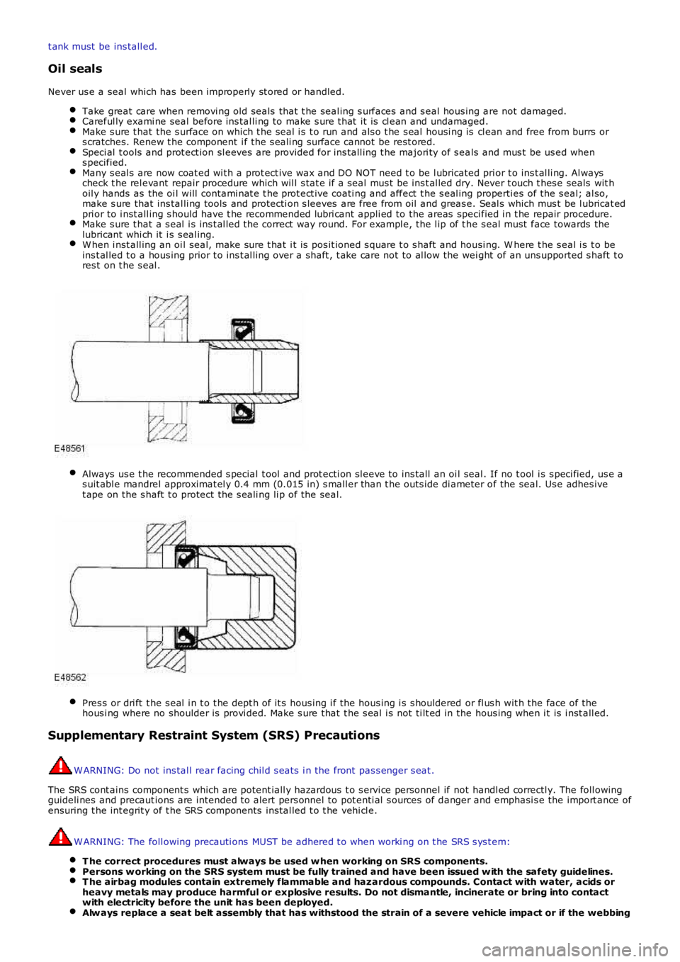
Take great care when removi ng old seals that t he seal ing s urfaces and s eal hous ing are not damaged.Careful ly exami ne seal before ins tal li ng to make s ure t hat it is cl ean and undamaged.Make s ure t hat the s urface on which t he s eal i s t o run and als o t he s eal housi ng is cl ean and free from burrs ors cratches. Renew t he component i f the s eali ng surface cannot be rest ored.Speci al t ools and prot ect ion sl eeves are provided for ins tall ing t he majori ty of s eals and mus t be us ed whens pecified.Many s eal s are now coat ed wi th a prot ect ive wax and DO NOT need t o be l ubricated prior t o ins t al li ng. Al wayscheck t he rel evant repair procedure which wil l s tat e if a seal mus t be ins t al led dry. Never t ouch t hes e seals wit hoil y hands as the oi l will contami nat e t he prot ect ive coati ng and affect t he s eal ing properti es of the s eal; al so,make s ure that ins tal li ng tools and protecti on s leeves are free from oil and greas e. Seal s which mus t be l ubricat edpri or to i nst all ing s hould have t he recommended lubri cant appli ed to the areas specified i n t he repair procedure.Make s ure t hat a s eal i s ins t al led t he correct way round. For exampl e, the l ip of t he s eal must face towards thelubricant whi ch it i s s eal ing.W hen i nst all ing an oi l seal, make sure t hat i t is pos it ioned s quare t o s haft and housi ng. W here t he s eal i s t o beins t al led t o a hous ing prior t o ins t al li ng over a shaft , t ake care not to al low the wei ght of an uns upported s haft t ores t on t he s eal .
Always us e t he recommended s pecial t ool and prot ecti on sl eeve to ins tall an oi l seal. If no t ool i s s peci fied, us e as uit abl e mandrel approximat el y 0.4 mm (0.015 in) s mall er than t he outs ide di ameter of the seal. Us e adhes ivet ape on the s haft t o protect the s eali ng li p of the seal.
Pres s or dri ft t he s eal i n t o t he dept h of it s hous ing i f the hous ing i s s houldered or fl us h wit h the face of thehous i ng where no shoulder is provi ded. Make s ure that t he s eal i s not ti lt ed in the hous ing when i t is i nst all ed.
Supplementary Restraint System (SRS) Precautions
W ARNING: Do not ins tal l rear facing chil d s eat s i n the front pas s enger s eat .
The SRS cont ains component s which are potent iall y hazardous t o s ervi ce personnel if not handl ed correctl y. The foll owingguideli nes and precaut ions are intended t o alert pers onnel to pot enti al s ources of danger and emphasi s e the import ance ofensuring t he int egrit y of t he SRS components ins tal led t o t he vehi cl e.
W ARNING: The foll owing precauti ons MUST be adhered t o when worki ng on t he SRS s ys t em:
T he correct procedures must always be used w hen working on SRS components.Persons w orking on the SRS system must be fully trained and have been issued w ith the safety guidelines.T he airbag modules contain extremely flammable and hazardous compounds. Contact with water, acids orheavy metals may produce harmful or explosive results. Do not dismantle, incinerate or bring into contactwith electricity before the unit has been deployed.Alw ays replace a seat belt assembly that has withstood the strain of a severe vehicle impact or if the webbing
Page 24 of 3229
shows signs of fraying.Alw ays disconnect the vehicle battery before carrying out any electric welding on a vehicle installed with anSRS system.
CAUTION: Do not expos e ai rbag modules or s eat belt pre-tens ioners t o t emperat ures exceeding 85° C (185° F).
It should be not ed t hat thes e precaut ions are not res trict ed to operat ions performed when s ervicing t he SRS s yst em. Thes ame care s hould be exerci sed when working on ancil lary sys t ems and components located i n the vi ci nit y of SRScomponents ; t hese include but are not l imi ted t o:
Steering wheel ai rbag, rot ary coupler.Pass enger front airbag.Side curt ain ai rbag modules - front and rear.Seat bel t pre-t ensi oners .SRS harnes ses , li nk leads and connectors.Side (t horax) ai r bags .
Making t he s ys t em s afe
Before working on or in t he vicini ty of SRS component s , make s ure t he s ys t em i s rendered safe by performi ng the foll owingoperati ons :
Remove the remot e cont rol .Dis connect batt ery, eart h lead first .W ai t 2 mi nut es for t he SRS power ci rcuit t o di scharge before commenci ng work.
• NOTE: The SRS us es energy res erve capaci tors to keep t he s yst em act ive i n t he event of electrical supply fail ure undercras h condi ti ons . It is necess ary to al low the capaci tors s uffi ci ent ti me t o dis charge (2 mi nut es ) in order t o avoid t he ris kof accidental deployment.
Ins t allat ion
In order to make s ure s ys tem int egrit y, it is ess enti al t hat the SRS sys tem is regularl y checked and mai nt ained s o t hat itis ready for effecti ve operat ion in t he event of a col lis i on. Carefully ins pect SRS component s before ins tal lati on. Do notins t al l a part t hat shows s i gns of being dropped or i mproperl y handl ed, s uch as dents , cracks or deformat ion.
W ARNING: The integrit y of the SRS sys tems is crit ical for safety reasons . Make s ure t he fol lowing precaut ions arealways adhered t o:
Do not install accessories or other objects to trim panels w hich cover airbags.Never install used SRS components from another vehicle or attempt to repair an SRS component.When repairing an SRS system, only use genuine new parts.Never apply electrical power to an SRS component unless instructed to do so as part of an approved testprocedure.Special fixings are necessary for installing an airbag module – do not use other fixings.Alw ays use new fixings w hen replacing an SRS component and make sure that all fixings are tightened to thecorrect torque.
• CAUTIO NS:
Take care not t o t rap airbag modules when i nst all ing i nt eri or trim components .
Make s ure SRS components are not cont aminat ed by oil or greas e.
• NOTE: Followi ng s eat bel t pre-t ensi oner deployment, t he s eat bel ts can s t ill be used as convent ional seat belt s but wil lneed to be replaced as s oon as poss i bl e t o make s ure full SRS protecti on. Do not us e t he s eat bel ts if t he ret racti onmechani sm i s not working correct ly.
• NOTE: If the SRS component s are to be repl aced, the part number/bar code of the new uni t mus t be recorded.
SRS component t es t ing precauti ons
The SRS component s are t riggered us ing relati vel y l ow operati ng current s, al ways adhere to the foll owing :
W ARNING: Never us e a mul ti meter or ot her general purpose equi pment on SRS components. Us e only Land Roverapproved diagnos t ic equipment t o diagnos e sys tem faul ts .
Page 30 of 3229
Air condi ti oning unit s mus t not be li ft ed by t hei r hos es , pipes or capil lary li nes .Hos es and lines mus t not be s ubjected t o any t wis t or s tress ; t he efficiency of the s ys tem wil l be impai red by ki nksor res trict ions. Make s ure that hos es are correct ly pos it ioned before t ightening coupli ngs , and make s ure that allclips and support s are ut il is ed.Flexible hos es s houl d not be pos it ioned cl oser t han 100 mm (4.0 i n) t o t he exhaus t manifold unl es s protected byheat shi el ding.Complet ed ass embli es mus t be checked for refrigerat ion l ines t ouching met al panels . Any direct contact ofcomponents and panels may t rans mit nois e and s o must be el iminated.The appropri at e t orque wrench must be us ed when t ight eni ng refri gerant connect ions to t he s ti pul at ed value. Anaddi ti onal s panner mus t be us ed t o hold t he union t o prevent t wis ti ng of the pi pe when t ightening connect ions .Before connecti ng any hos e or pipe, make s ure that refri gerant oil is appli ed t o t he seat of t he new O-ri ngs , BUTNOT to the t hreads of the connect ion.All prot ect ive pl ugs or caps mus t remai n i n place in the component unt il i mmediat el y pri or to connect ion.Make s ure component s are at room temperat ure before uncappi ng/unpl uggi ng, t o prevent condens at ion of moi s turefrom the ai r that enters it .W hen di sconnect ing, immedi ately pl ug or cap all air condi ti oni ng pipes t o prevent ingres s of dirt and mois t ure i ntot he sys t em.Component s mus t not remain uncapped/unpl ugged, if a sys t em has been left uncapped/unpl ugged for 20 mi nut esor longer, a new recei ver/drier mus t be i ns t alled.The receiver/dri er contai ns des i ccant which absorbs mois t ure. It must be pos it ively sealed at al l ti mes . Areceiver/dri er t hat has been left uncapped for longer t han 20 mi nutes mus t not be used; i nst all a new uni t.The receiver/dri er s hould be the l ast component connect ed to the sys tem t o make s ure opt imum dehydrat ion andmaximum moi st ure protecti on of the sys tem.W henever a component of t he refrigerat ion s yst em is repl aced, it will al so be neces sary t o ins t al l a newreceiver/dri er uni t.Us e alcohol and a cl ean li nt -free cl oth to cl ean di rt y connecti ons.Make s ure t hat all new part s i ns t alled are marked for us e wit h R134a.W hen a major repai r has been complet ed, a leak t es t s hould be conduct ed; refer t o t he Repai rs Secti on of thi smanual for the correct procedure.
Refrigerant oil
CAUTION: Refrigerant oil eas il y absorbs water and mus t not be s tored for long periods. Do not pour unusedrefri gerant oi l back i nto the container. Always use an approved refrigerant oi l.
W hen replaci ng component s in the ai r condit ioning s ys tem, drai n t he refri gerant oi l from t he component being replacedint o a graduat ed cont ainer. On as s embly, add t he quant it y of refri gerant oi l drained t o t he new component - See Ai rCondi ti oni ng Compres s or Repl acement in this Sect ion.
Compres s or
A new compress or is sealed and press uris ed wit h Ni trogen gas . W hen i nst all ing a new compres sor, sl owly releas e thes eal ing cap; gas pres sure s houl d be heard to vent as t he s eal i s broken.
CAUTION: A new compress or s houl d always be s ealed and could be pres suris ed wit h ni trogen gas . To avoid pos si bleoil l os s , rel eas e t he s ealing cap(s ) s lowl y. Do not remove t he cap(s ) unt il i mmediatel y pri or to connect ing t he aircondi ti oni ng pipes t o the compress or.
Rapid refrigerant dis charge
If the ai r condit ioning s ys tem is i nvol ved in accident damage and t he s yst em is punct ured, t he refri gerant will di schargerapi dl y. The rapid di scharge of refrigerant wil l als o res ult in t he los s of mos t of the oi l from t he s yst em. The compres sormus t be removed and al l the remaining oi l in t he compres s or drained and refil led as i nst ruct ed in t he air condit ionings ect ion of t his manual.
Precaut ions for refrigerant recovery, recycl ing and rechargi ng
W hen t he air condit ioning s yst em is recharged, any exi s ti ng refri gerant i s first recovered from t he s ys t em and recycled.The s ys t em i s t hen charged wit h the required weight of refrigerant and volume of refrigerant oil .
W ARNING: Refri gerant mus t al ways be recycl ed before reus e t o make s ure that the purit y of the refrigerant i s highenough for s afe us e i n the ai r condit ioni ng sys t em. Recycl ing s hould al ways be carried out wit h equipment which i s des i gncert ifi ed by Underwrit er Laborat ory Inc. for compl iance wit h SAE J1991. Ot her equipment may not recycle refrigerant t o t herequired level of purit y.
• CAUTIO NS:
A R134a Refri gerant Recovery Recycli ng Rechargi ng Stat ion mus t not be us ed wit h any ot her t ype of refrigerant .Refrigerant R134a from domes ti c and commercial s ources mus t not be used i n mot or vehi cl e air condi ti oni ng s yst ems .
The s yst em must be evacuat ed i mmediat el y before recharging commences. Del ay bet ween evacuati on and rechargingis not permit ted.
Air Condit ioning Compress or Repl acement
A new compress or is suppli ed fi ll ed wit h a full charge (X cm³) of refrigerant oi l.
A calculat ed quant it y of oil mus t be drai ned from t he new compres s or before i nst all ing. To cal cul at e t he quant it y of oil t obe drai ned:
Remove the drain pl ug from the ol d compres sor.