2006 LAND ROVER FRELANDER 2 key battery
[x] Cancel search: key batteryPage 14 of 3229
Publi s hed: 11-May-2011
General Information - Standard Workshop Practices
Des cript ion and Operat ion
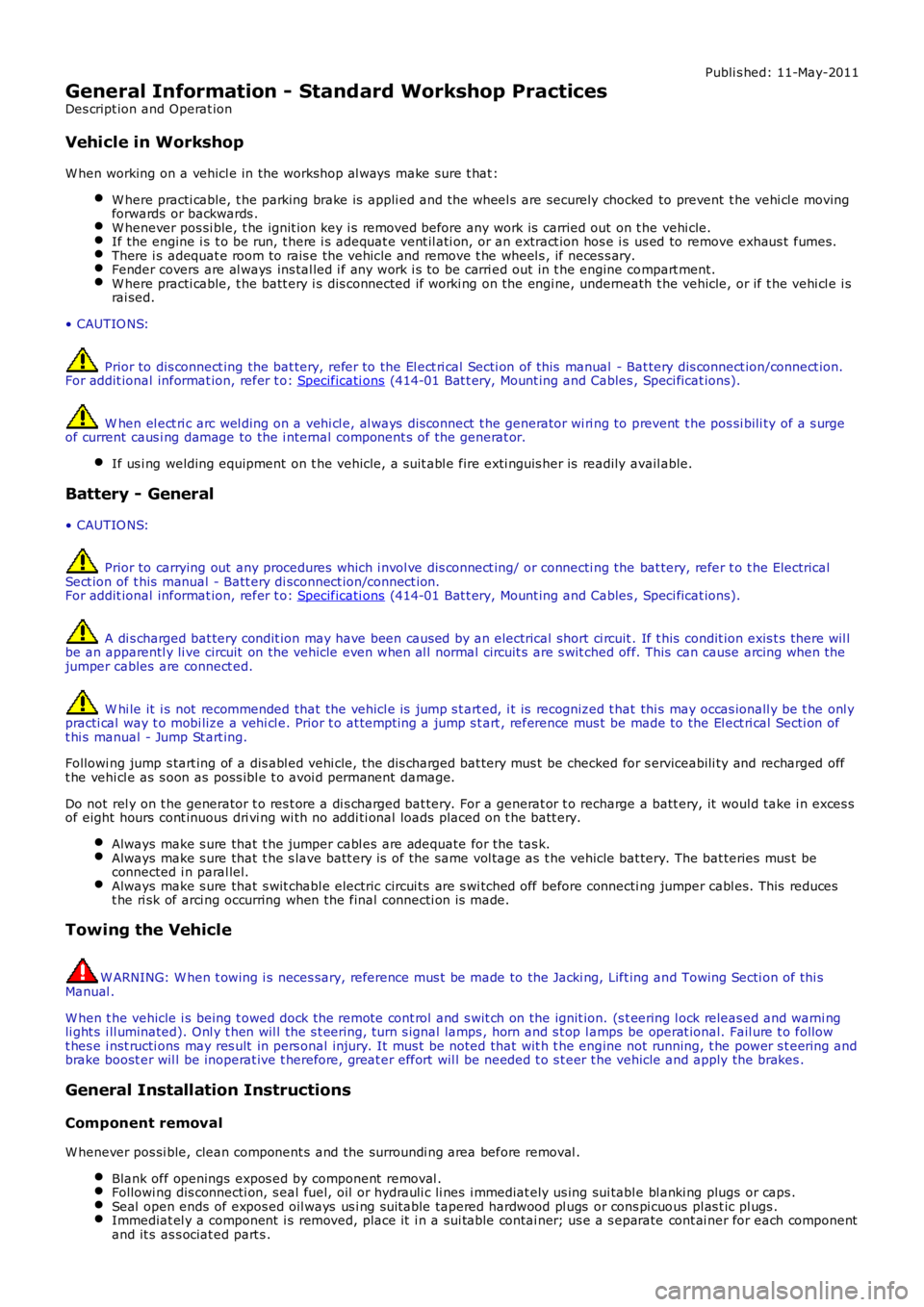
Vehicle in Workshop
W hen working on a vehicl e in the workshop al ways make sure t hat :
W here practi cable, t he parking brake is appli ed and t he wheel s are securely chocked to prevent t he vehi cl e movingforwards or backwards .W henever pos si ble, t he ignit ion key i s removed before any work is carried out on t he vehi cle.If the engine i s t o be run, t here i s adequat e vent il ati on, or an extract ion hos e i s us ed to remove exhaus t fumes.There i s adequat e room to rais e the vehicle and remove t he wheel s , if neces s ary.Fender covers are al ways ins tal led i f any work i s to be carri ed out in t he engine compart ment.W here practi cable, t he batt ery i s dis connected if worki ng on the engi ne, underneath t he vehicle, or if t he vehi cl e i srai sed.
• CAUTIO NS:
Prior to dis connect ing the bat tery, refer to the El ect ri cal Secti on of this manual - Bat tery dis connect ion/connect ion.For addit ional informat ion, refer t o: Specificati ons (414-01 Bat t ery, Mount ing and Cables , Speci ficat ions).
W hen el ect ri c arc wel ding on a vehi cl e, al ways dis connect t he generator wi ri ng to prevent t he pos si bili ty of a s urgeof current caus i ng damage to the i nternal component s of the generat or.
If us i ng welding equipment on t he vehicle, a s uit abl e fire exti nguis her is readily avail able.
Battery - General
• CAUTIO NS:
Prior to carrying out any procedures which i nvol ve dis connect ing/ or connecti ng the bat tery, refer t o t he ElectricalSect ion of t his manual - Batt ery di sconnect ion/connect ion.For addit ional informat ion, refer t o: Specificati ons (414-01 Bat t ery, Mount ing and Cables , Speci ficat ions).
A di s charged bat tery condit ion may have been caus ed by an electrical short ci rcuit . If t his condit ion exis t s there wil lbe an apparentl y li ve circuit on the vehicle even when al l normal circuit s are s wit ched off. This can cause arcing when t hejumper cables are connect ed.
W hi le it i s not recommended that the vehicl e is jump s t art ed, i t is recognized t hat thi s may occas ionall y be t he onl ypracti cal way t o mobi lize a vehi cl e. Prior t o at tempt ing a jump s t art , reference must be made to the El ect ri cal Secti on oft hi s manual - Jump St art ing.
Followi ng jump s tart ing of a dis abl ed vehi cle, the di s charged bat tery mus t be checked for s erviceabili ty and recharged offt he vehi cl e as s oon as poss ibl e t o avoi d permanent damage.
Do not rel y on t he generator t o res t ore a di s charged bat tery. For a generat or t o recharge a batt ery, it woul d take i n exces sof eight hours cont inuous dri vi ng wi th no addi ti onal loads placed on t he batt ery.
Always make s ure that t he jumper cabl es are adequate for the tas k.Always make s ure that t he s lave batt ery i s of the same vol tage as t he vehicle bat tery. The bat teries mus t beconnected i n paral lel.Always make s ure that s wit chabl e electric circui ts are s wi tched off before connecti ng jumper cabl es. This reducest he ri sk of arci ng occurring when the final connecti on is made.
Towing the Vehicle
W ARNING: W hen t owing i s neces sary, reference mus t be made to the Jacki ng, Lift ing and Towing Secti on of thi sManual .
W hen t he vehicle i s being t owed dock the remote cont rol and s wit ch on the ignit ion. (s t eering l ock releas ed and warni ngli ght s i ll uminated). Onl y t hen wil l the s t eering, turn s ignal lamps , horn and s t op lamps be operat ional. Fail ure t o followt hes e i nst ructi ons may res ult in pers onal injury. It mus t be noted that wit h t he engine not running, t he power s t eering andbrake boost er wil l be inoperat ive t herefore, great er effort wil l be needed t o s t eer t he vehicle and apply the brakes .
General Installation Instructions
Component removal
W henever pos si ble, clean component s and the surroundi ng area before removal .
Blank off openings expos ed by component removal .Followi ng dis connecti on, s eal fuel, oil or hydrauli c li nes i mmediat ely us ing sui table bl anki ng plugs or caps .Seal open ends of expos ed oil ways us i ng sui table tapered hardwood pl ugs or cons pi cuous pl as t ic pl ugs .Immediat el y a component i s removed, place it i n a sui table contai ner; us e a s eparate cont ai ner for each componentand it s as s ociat ed part s .
Page 1754 of 3229
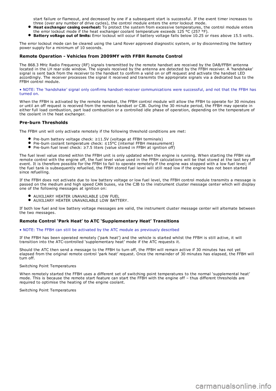
s tart fail ure or flameout, and decreas ed by one if a subs equent s tart is succes s ful . If t he event t imer i ncreas es t ot hree (over any number of drive cycl es), the cont rol module ent ers t he error lockout mode.Heat exchanger casing overheat: To prot ect t he s ys t em from exces s ive t emperatures , t he cont rol module ent erst he error l ockout mode if t he heat exchanger coolant temperat ure exceeds 125 °C (257 °F).Battery voltage out of limits: Error lockout wi ll occur if bat tery vol tage fall s bel ow 10.25 or ris es above 15.5 volt s .
The error lockout mode can be cleared usi ng the Land Rover approved di agnos ti c s ys t em, or by dis connect ing the bat terypower supply for a mi nimum of 10 s econds.
Remote Operation - Vehicles from 2009MY with FFBH Remote Control
The 868.3 MHz Radi o Frequency (RF) si gnal s t ransmit ted by the remote hands et are recei ved by the DAB/FFBH ant ennalocated i n t he LH rear s i de window. The s ignal s received by t he antenna are detected by t he FFBH receiver. A 'handshake's ignal is s ent back from the recei ver t o t he hands et t o confirm a val id on or off reques t and act ivate the handset LEDaccordi ngl y. The recei ver proces s es the s i gnal it recei ved and trans mi ts the appropriate si gnal s via a dedi cat ed bus t o theFFBH cont rol module.
• NOTE: The ‘handshake’ si gnal only confi rms hands et-receiver communi cat ions were s uccess ful , and not that t he FFBH hast urned on.
W hen t he FFBH is act ivated by the remote hands et, t he FFBH cont rol module will al low t he FFBH t o operate for 30 minutesor unt il an off request is received from t he remot e hands et or CJB. During t he 30 minut e period, the FFBH may operat e i neit her full l oad combus ti on, part load combus t ion or a controll ed idle phas e of operat ion, depending on t he t emperature oft he coolant i n t he heat exchanger.
Pre-burn Thresholds
The FFBH unit wi ll only acti vat e remotely if t he fol lowing thres hold condit ions are met:
Pre-burn batt ery vol tage check: ≥11.5V (volt age at FFBH terminals )Pre-burn coolant temperat ure check: ≤15°C (int ernal FFBH measurement )Pre-burn fuel l evel check: ≥7.5 lit ers (value s t ored i n FFBH at ignit ion off)
The fuel level val ue s tored wit hin t he FFBH unit i s only updated when t he engine i s running. W hen s t art ing t he FFBH viaremot e control wit h the engi ne off, the fuel l evel value us ed in the FFBH calculat ions wi ll be t hat s t ored at t he las t key offevent . It i s t herefore poss ibl e for t he FFBH t o fai l to operat e remotel y if t he engine was s t opped wi th a low fuel level; i ft he fuel tank i s s ubs equent ly refuell ed, the FFBH s t ored fuel l evel wil l st il l read l ow i f the engine has not been s tarteds ince refuel li ng.
If the FFBH does not act ivate due to low bat tery vol tage or l ow fuel l evel, t he FFBH cont rol module transmit s a mes s age ispass ed on t he medi um and high speed CAN bus es, vi a t he CJB to the i nst rument clus ter mes s age cent er which wil l dis playone of the foll owing mes s ages at i gnit ion on:
AUXILIARY HEATER UNAVAILABLE LOW FUELAUXILIARY HEATER UNAVAILABLE LOW BATTERY .
If bot h l ow fuel and low batt ery volt age mes sages are val id, t he ins trument cl ust er mes sage center wi ll alt ernate bet weent he two mes sages .
Remote Control ‘Park Heat’ to ATC ‘Supplementary Heat’ Transitions
• NOTE: The FFBH can s ti ll be acti vat ed by t he ATC module as previ ous l y descri bed
If the FFBH has been operated remot el y (‘park heat’) and the vehicl e is st art ed whilst the FFBH i s s ti ll act ive, it willt ransi ti on int o t he ATC-control led ‘s upplement ary heat’ mode if t he ATC request s i t.
Shoul d t he ATC t hen send a mess age t o t he FFBH to turn off, the FFBH will remain active if 30 minut es has not yetelaps ed from t he ori ginal remot e cont rol ‘park heat ’ request . Once t he remai nder of 30 mi nut es has elaps ed, t he FFBH wil lt urn off.
Swit chi ng Point Temperatures
W hen remotel y s tarted t he FFBH us es a different s et of s wit chi ng poi nt temperat ures t o t he normal ‘supplement al heat’mode. Thi s is because the remot e s tart feature can s tart the FFBH wi th the engine off – t hus different t hres hol ds arerequired t o opti mis e t he heati ng of the engine coolant.
Swit chi ng Point Temperatures
Page 1811 of 3229
Publi s hed: 11-May-2011
Battery and Charging System - General Information -
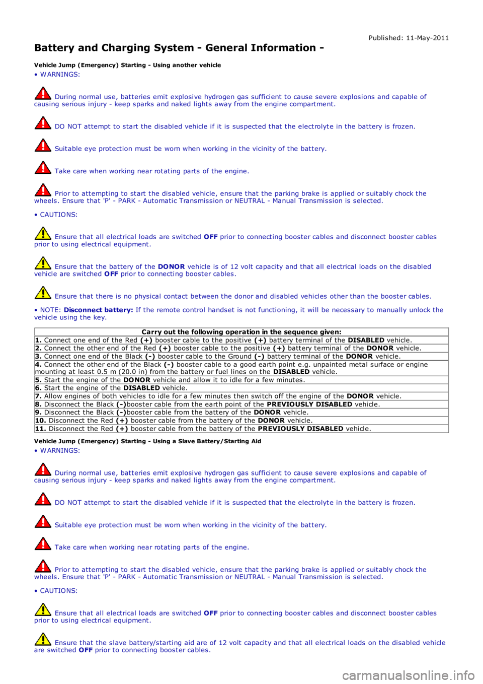
Vehicle Jump (Emergency) Starting - Using another vehicle
• W ARNINGS:
During normal us e, bat t eries emi t expl osi ve hydrogen gas suffi ci ent t o cause severe expl os i ons and capabl e ofcaus ing serious injury - keep s parks and naked li ght s away from the engine compart ment.
DO NOT at tempt t o s tart the di s abl ed vehi cl e i f it is sus pect ed t hat t he elect rolyte in the bat tery is frozen.
Suit able eye prot ect ion must be worn when working i n t he vicinit y of t he bat t ery.
Take care when working near rot at ing parts of t he engine.
Prior to att empti ng to st art t he dis abled vehicle, ens ure t hat the parki ng brake i s appl ied or s uit abl y chock t hewheels . Ens ure that 'P' - PARK - Aut omati c Trans mis s ion or NEUTRAL - Manual Trans mi ss i on is s elect ed.
• CAUTIO NS:
Ens ure t hat al l electrical l oads are s wi tched OFF pri or to connect ing boos ter cabl es and dis connect boos t er cablespri or to us ing el ect ri cal equipment .
Ens ure t hat the bat tery of the DO NOR vehicle is of 12 volt capaci ty and that all electrical loads on t he dis abl edvehi cl e are s wit ched O FF prior t o connecti ng boost er cables .
Ens ure t hat there is no phys ical contact between t he donor and di sabl ed vehi cl es other than t he boost er cabl es .
• NOTE: Disconnect battery: If t he remote control hands et is not functi oning, it wi ll be neces s ary t o manuall y unlock thevehi cl e us ing t he key.
Carry out the following operation in the sequence given:
1. Connect one end of the Red (+) boos t er cable to t he pos it ive (+) batt ery terminal of the DISABLED vehicle.2. Connect t he other end of the Red (+) boos ter cable t o t he posi ti ve (+) batt ery t erminal of t he DONOR vehicle.
3. Connect one end of the Black (-) boos ter cabl e t o t he Ground (-) bat t ery t ermi nal of t he DONOR vehi cle.
4. Connect t he other end of the Bl ack (-) boost er cabl e t o a good eart h point e.g. unpainted metal s urface or enginemounti ng at leas t 0.5 m (20.0 i n) from t he batt ery or fuel l ines on t he DISABLED vehi cle.
5. Start the engi ne of the DO NOR vehicle and al low it t o i dl e for a few minut es .6. Start the engi ne of the DISABLED vehicle.
7. All ow engines of both vehicles t o i dle for a few mi nut es t hen swi tch off the engine of t he DONO R vehicle.
8. Dis connect t he Black (-)boos t er cable from t he eart h point of t he PREVIO USLY DISABLED vehi cl e.9. Dis connect t he Black (-)boos t er cable from t he batt ery of t he DONO R vehicle.
10. Dis connect the Red (+) boos t er cable from t he batt ery of t he DONOR vehi cl e.
11. Dis connect the Red (+) boos t er cable from t he batt ery of t he PREVIOUSLY DISABLED vehi cl e.
Vehicle Jump (Emergency) Starting - Using a Slave Battery/Starting Aid
• W ARNINGS:
During normal us e, bat t eries emi t expl osi ve hydrogen gas suffi ci ent t o cause severe expl os i ons and capabl e ofcaus ing serious injury - keep s parks and naked li ght s away from the engine compart ment.
DO NOT at tempt t o s tart the di s abl ed vehi cl e i f it is sus pect ed t hat t he elect rolyte in the bat tery is frozen.
Suit able eye prot ect ion must be worn when working i n t he vicinit y of t he bat t ery.
Take care when working near rot at ing parts of t he engine.
Prior to att empti ng to st art t he dis abled vehicle, ens ure t hat the parki ng brake i s appl ied or s uit abl y chock t hewheels . Ens ure that 'P' - PARK - Aut omati c Trans mis s ion or NEUTRAL - Manual Trans mi ss i on is s elect ed.
• CAUTIO NS:
Ens ure t hat al l electrical l oads are s wi tched OFF pri or to connect ing boos ter cabl es and dis connect boos t er cablespri or to us ing el ect ri cal equipment .
Ens ure t hat the s l ave bat tery/s tarti ng aid are of 12 volt capacit y and t hat al l elect rical l oads on the di sabl ed vehi cl eare swi tched OFF prior t o connecti ng boos t er cables .
Page 1813 of 3229
Publi shed: 14-Jul-2011
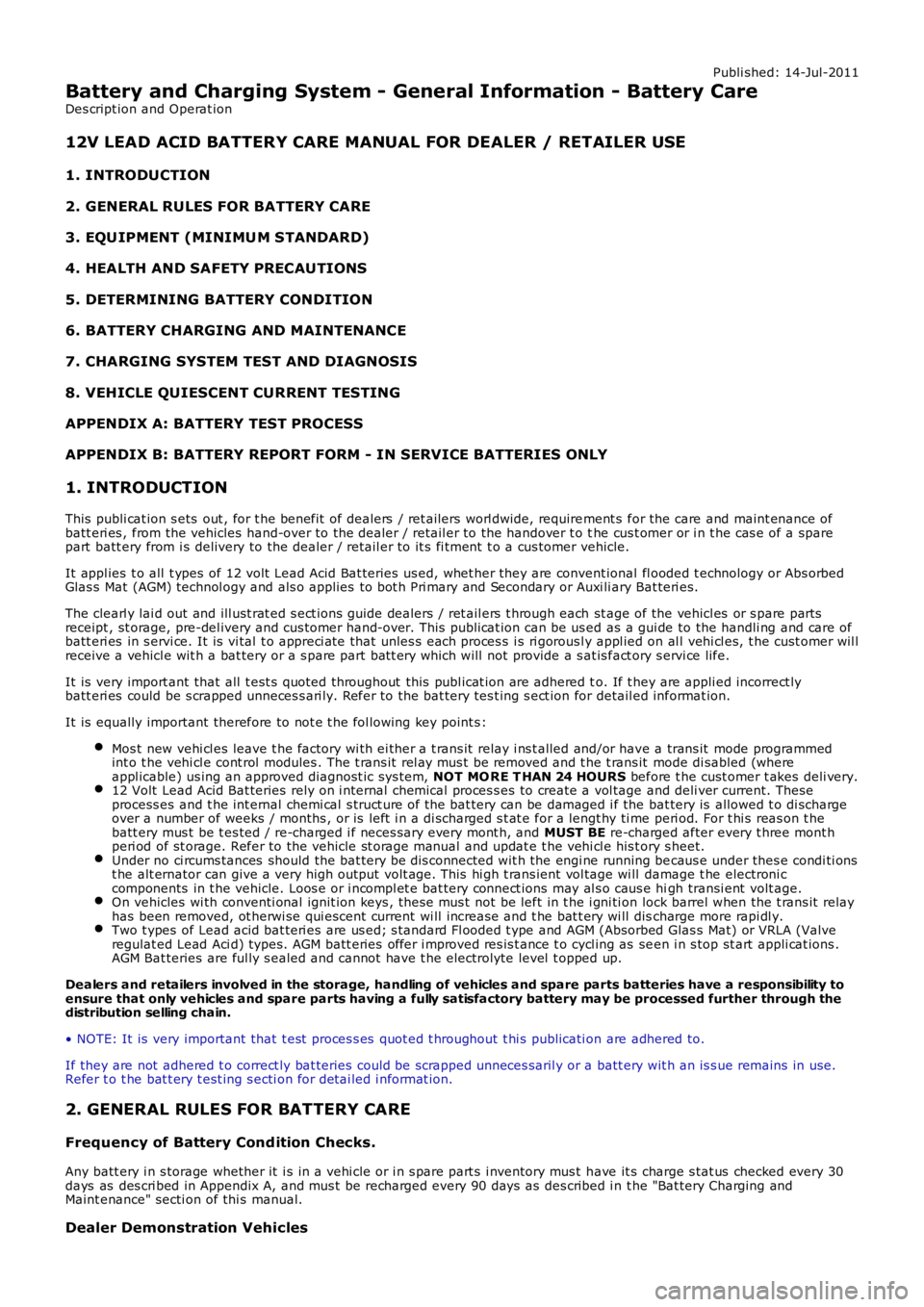
Battery and Charging System - General Information - Battery Care
Des cript ion and Operat ion
12V LEAD ACID BATTERY CARE MANUAL FOR DEALER / RETAILER USE
1. INTRODUCTION
2. GENERAL RULES FOR BATTERY CARE
3. EQU IPMENT (MINIMU M STANDARD)
4. HEALTH AND SAFETY PRECAUTIONS
5. DETERMINING BATTERY CONDITION
6. BATTERY CHARGING AND MAINTENANCE
7. CHARGING SYSTEM TEST AND DIAGNOSIS
8. VEHICLE QUIESCENT CURRENT TESTING
APPENDIX A: BATTERY TEST PROCESS
APPENDIX B: BATTERY REPORT FORM - IN SERVICE BATTERIES ONLY
1. INTRODUCTION
This publi cat ion s ets out , for t he benefit of dealers / ret ailers worl dwide, requirement s for the care and maint enance ofbatt eri es , from the vehicles hand-over to the dealer / retail er to the handover t o the cus t omer or i n t he cas e of a sparepart batt ery from i s delivery to the dealer / retail er to it s fi tment t o a cus tomer vehicle.
It appl ies t o all t ypes of 12 volt Lead Acid Bat teries us ed, whet her they are convent ional fl ooded t echnology or Abs orbedGlas s Mat (AGM) technol ogy and als o applies to bot h Pri mary and Secondary or Auxi li ary Bat teri es.
The clearl y lai d out and ill ust rat ed s ect ions guide dealers / ret ail ers t hrough each st age of the vehicl es or s pare partsreceipt , st orage, pre-del ivery and cus tomer hand-over. This publi cat ion can be us ed as a gui de to the handli ng and care ofbatt eri es in s ervi ce. It is vi tal t o appreci ate that unles s each proces s i s ri gorousl y appl ied on al l vehi cl es, t he cust omer wil lreceive a vehicl e wit h a bat tery or a s pare part bat t ery which will not provide a s at is fact ory s ervi ce life.
It is very import ant that all t est s quoted throughout this publ icat ion are adhered to. If t hey are appli ed incorrect lybatt eri es could be s crapped unneces s ari ly. Refer to the bat tery tes t ing s ect ion for detail ed informat ion.
It is equally important therefore to not e t he fol lowing key point s :
Mos t new vehi cl es leave t he factory wi th ei ther a t rans it relay i ns t alled and/or have a trans it mode programmedint o t he vehi cl e cont rol modules . The t rans it rel ay mus t be removed and t he t rans it mode di sabled (whereappl icable) us ing an approved diagnost ic sys tem, NOT MO RE T HAN 24 HOURS before t he cust omer t akes deli very.12 Volt Lead Acid Bat teries rely on i nternal chemical proces s es to create a vol tage and deli ver current. Theseprocess es and t he int ernal chemi cal s truct ure of the bat tery can be damaged i f the bat tery is allowed t o di schargeover a number of weeks / months , or is left i n a di scharged s t at e for a lengt hy ti me peri od. For t hi s reas on t hebatt ery mus t be t es ted / re-charged i f neces sary every mont h, and MUST BE re-charged after every t hree mont hperi od of st orage. Refer to the vehicle st orage manual and updat e t he vehi cl e his t ory s heet.Under no ci rcums tances should the bat tery be dis connected wit h the engi ne running becaus e under thes e condi ti onst he alt ernator can give a very high output volt age. This hi gh t rans ient vol tage wi ll damage t he electroni ccomponents in t he vehicle. Loos e or i ncompl et e bat tery connect ions may al s o caus e high transi ent volt age.On vehicles wi th conventi onal ignit ion keys , thes e mus t not be left in t he i gni ti on lock barrel when the t rans it relayhas been removed, ot herwi se qui escent current wi ll increas e and t he bat t ery wi ll discharge more rapi dl y.Two t ypes of Lead acid bat teri es are us ed; s tandard Fl ooded t ype and AGM (Absorbed Glas s Mat) or VRLA (Valveregulat ed Lead Aci d) types. AGM batt eries offer i mproved res is t ance t o cycl ing as seen i n s top st art appli cat ions .AGM Bat teries are ful ly s ealed and cannot have t he electrolyte level t opped up.
Dealers and retailers involved in the storage, handling of vehicles and spare parts batteries have a responsibility toensure that only vehicles and spare parts having a fully satisfactory battery may be processed further through thedistribution selling chain.
• NOTE: It is very important that t est proces s es quot ed t hroughout t hi s publicati on are adhered to.
If they are not adhered t o correct ly bat teries could be scrapped unneces saril y or a batt ery wit h an is s ue remains in use.Refer t o t he bat t ery t est ing s ecti on for detai led i nformat ion.
2. GENERAL RULES FOR BATTERY CARE
Frequency of Battery Cond ition Checks.
Any batt ery i n s torage whether it i s in a vehi cle or i n s pare part s i nventory mus t have it s charge s tat us checked every 30days as des cri bed in Appendix A, and mus t be recharged every 90 days as des cribed i n t he "Bat tery Charging andMaint enance" secti on of thi s manual.
Dealer Demonstration Vehicles
Page 1827 of 3229
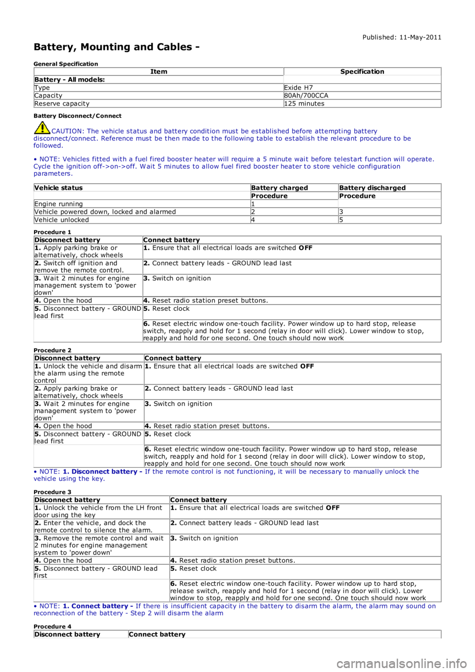
Publi s hed: 11-May-2011
Battery, Mounting and Cables -
General SpecificationItemSpecification
Battery - All models:
TypeExide H7Capaci ty80Ah/700CCA
Res erve capacit y125 minutes
Battery Disconnect/C onnect
CAUTION: The vehicle s t atus and batt ery condit ion mus t be es t abl is hed before att empti ng bat t erydis connect/connect . Reference mus t be t hen made t o t he fol lowing table to es t abl is h t he rel evant procedure t o befol lowed.
• NOTE: Vehicles fit ted wit h a fuel fired boos t er heat er will requi re a 5 mi nute wait before tel es t art funct ion wi ll operate.Cycl e t he ignit ion off->on->off. W ai t 5 mi nutes t o all ow fuel fired boos t er heat er to s t ore vehicle confi gurati onparamet ers .
Vehicle statusBattery chargedBattery discharged
ProcedureProcedure
Engine runni ng1Vehicle powered down, l ocked and alarmed23
Vehicle unl ocked45
Procedure 1
Disconnect batteryConnect battery1. Apply parki ng brake oralt ernat ively, chock wheels1. Ens ure that all el ect ri cal loads are s wit ched O FF
2. Swit ch off i gni ti on andremove the remote cont rol.2. Connect bat t ery l eads - GROUND lead l ast
3. W ai t 2 mi nut es for enginemanagement sys tem t o 'powerdown'
3. Swit ch on ignit ion
4. Open t he hood4. Reset radi o s tat ion preset but tons .
5. Dis connect batt ery - GROUNDl ead firs t5. Reset clock
6. Reset elect ric window one-t ouch facili ty. Power window up t o hard s top, rel eas es wit ch, reapply and hol d for 1 s econd (relay i n door wil l cl ick). Lower window t o s top,reapply and hold for one s econd. One t ouch s hould now work
Procedure 2
Disconnect batteryConnect battery
1. Unlock t he vehi cl e and dis armt he alarm us ing t he remotecont rol
1. Ensure t hat al l el ect ri cal l oads are s wit ched OFF
2. Apply parki ng brake oralt ernat ively, chock wheels2. Connect batt ery l eads - GROUND l ead las t
3. W ai t 2 mi nut es for enginemanagement sys tem t o 'powerdown'
3. Swit ch on i gni ti on
4. Open t he hood4. Res et radio s t ati on pres et but tons .
5. Dis connect batt ery - GROUNDl ead firs t5. Res et cl ock
6. Res et el ect ri c window one-touch facil it y. Power window up to hard s top, rel eases wit ch, reappl y and hold for 1 s econd (rel ay in door wil l cl ick). Lower window t o s top,reapply and hol d for one s econd. One t ouch should now work
• NOTE: 1. Disconnect battery - If the remot e cont rol is not funct ioning, it will be necess ary to manual ly unlock thevehi cl e us ing t he key.
Procedure 3
Disconnect batteryConnect battery1. Unlock t he vehi cl e from the LH frontdoor us i ng the key1. Ens ure t hat al l electrical l oads are s wi tched OFF
2. Enter t he vehi cl e, and dock t heremote control to si lence the al arm.2. Connect batt ery leads - GROUND l ead las t
3. Remove t he remot e cont rol and wai t2 minutes for engi ne managements yst em to 'power down'
3. Swi tch on i gni ti on
4. Open t he hood4. Res et radio st ati on pres et but t ons .
5. Dis connect batt ery - GROUND leadfirst5. Res et cl ock
6. Res et el ect ri c wi ndow one-touch facil it y. Power wi ndow up to hard s t op,release s wit ch, reapply and hol d for 1 second (relay i n door wil l cl ick). Lowerwi ndow to s top, reapply and hold for one s econd. One t ouch s hould now work
• NOTE: 1. Connect battery - If there is ins uffi cient capacit y in the bat tery to di s arm the al arm, t he alarm may sound onreconnect ion of t he bat t ery - St ep 2 wi ll dis arm t he alarm
Procedure 4
Disconnect batteryConnect battery
Page 2313 of 3229
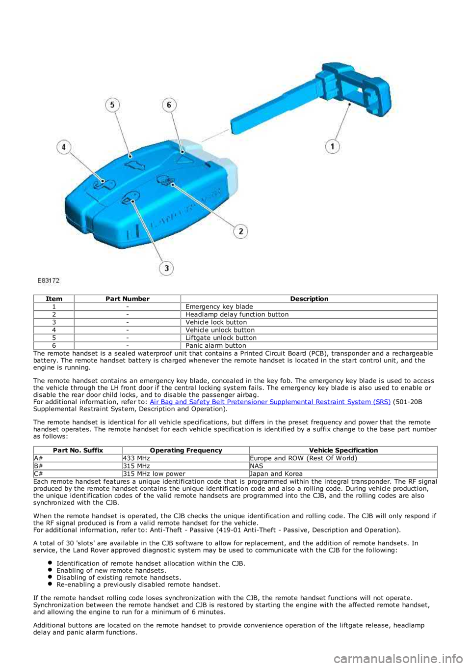
ItemPart NumberDescription1-Emergency key bl ade2-Headl amp delay funct ion but ton3-Vehicl e l ock button4-Vehicl e unlock button5-Li ftgate unlock butt on6-Panic alarm buttonThe remote hands et is a seal ed wat erproof uni t t hat contains a Printed Ci rcuit Board (PCB), transponder and a rechargeablebattery. The remote hands et batt ery i s charged whenever the remote hands et is located i n the s tart cont rol unit , and t heengi ne is running.
The remote hands et cont ai ns an emergency key blade, conceal ed in t he key fob. The emergency key bl ade i s us ed to acces sthe vehicle through the LH front door i f t he central locki ng syst em fai ls. The emergency key bl ade is als o us ed t o enable ordis able t he rear door chil d locks , and t o dis able t he pas senger ai rbag.For addit ional informat ion, refer t o: Ai r Bag and Safet y Belt Pretens ioner Supplement al Rest raint Sys tem (SRS) (501-20BSupplemental Res traint Sys tem, Des cription and Operat ion).
The remote hands et is identi cal for all vehicl e s peci ficat ions, but di ffers in t he pres et frequency and power that the remotehandset operates. The remot e handset for each vehicle specificat ion is ident ifi ed by a s uffix change to the base part numberas follows:
Part No. SuffixOperating FrequencyVehicle SpecificationA#433 MHzEurope and ROW (Rest Of W orld)B#315 MHzNASC#315 MHz low powerJapan and KoreaEach remot e handset features a uni que ident ifi cation code that is programmed within t he integral trans ponder. The RF si gnalproduced by t he remot e handset contains t he uni que ident ifi cation code and also a rolli ng code. Duri ng vehicl e product ion,the unique identification codes of the valid remot e handsets are programmed int o the CJB, and the roll ing codes are al sosynchronized wi th the CJB.
W hen the remote handset is operat ed, t he CJB checks t he unique i dent ificat ion and rol ling code. The CJB will only respond ifthe RF si gnal produced is from a val id remote hands et for the vehicle.For addit ional informat ion, refer t o: Anti -Theft - Pas si ve (419-01 Anti -Theft - Pas si ve, Des cript ion and Operati on).
A tot al of 30 'sl ots ' are availabl e in the CJB s oftware to al low for repl acement, and the addi tion of remote hands et s. Inservi ce, t he Land Rover approved di agnost ic system may be us ed to communicat e wit h the CJB for the followi ng:
Identi ficati on of remote handset all ocat ion wit hin t he CJB.Enabli ng of new remot e handsets .Disabl ing of exist ing remote handsets .Re-enabling a previ ously disabled remot e handset.
If the remote hands et rolling code l os es synchronizati on with t he CJB, t he remot e handset funct ions will not operate.Synchronizati on between the remote hands et and CJB is rest ored by s tart ing t he engine wit h t he affect ed remot e handset,and all owing the engine to run for a minimum of 6 mi nutes.
Addi tional buttons are located on the remote hands et to provide convenience operati on of t he li ftgat e rel ease, headlampdelay and panic al arm functions .
Page 2763 of 3229

43
Keys and remote controls
R
Tailgate
Press briefly to release the tailgate.
Emergency alarm
Press and hold for three seconds, or
press twice within three seconds, to
activate the horn and the hazard
lamps.
Once active for more than five seconds the
alarm can be cancelled by pressing the button
and holding for three seconds, or pressing
twice within three seconds.
Note: The horn and hazard lamps will switch
off automatically after two minutes and forty
five seconds.
Remote battery
The remote control batteries are recharged
when the remote is docked and the engine is
running. For this reas on it is recommended
that each remote is used periodically. This will
ensure that the batteries are kept charged and
ready for use.
Page 2834 of 3229
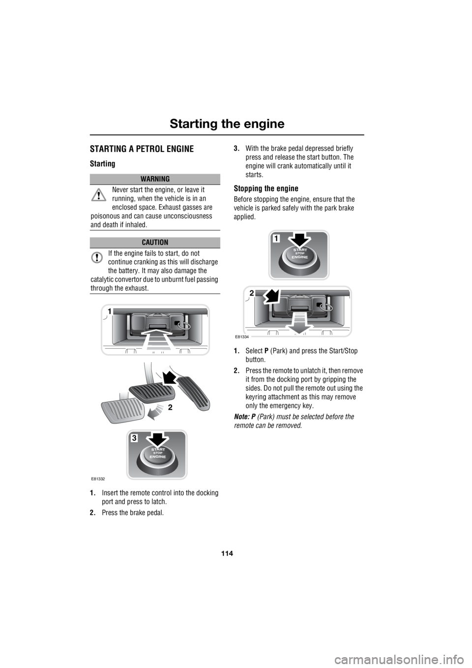
Starting the engine
114
L
STARTING A PETROL ENGINE
Starting
1. Insert the remote control into the docking
port and press to latch.
2. Press the brake pedal. 3.
With the brake peda l depressed briefly
press and release the start button. The
engine will crank auto matically until it
starts.
Stopping the engine
Before stopping the engine, ensure that the
vehicle is parked safely with the park brake
applied.
1. Select P (Park) and press the Start/Stop
button.
2. Press the remote to unlatch it, then remove
it from the docking port by gripping the
sides. Do not pull the remote out using the
keyring attachment as this may remove
only the emergency key.
Note: P (Park) must be selected before the
remote can be removed.
WARNING
Never start the engine, or leave it
running, when the vehicle is in an
enclosed space. Exhaust gasses are
poisonous and can cau se unconsciousness
and death if inhaled.
CAUTION
If the engine fails to start, do not
continue cranking as this will discharge
the battery. It may also damage the
catalytic conver tor due to unburnt fuel passing
through the exhaust.
3
1
2
E81332
1
2
E81334