2006 LAND ROVER FRELANDER 2 start stop button
[x] Cancel search: start stop buttonPage 1216 of 3229
t he fan mot ors . The fan cont rol module confi rms the fan s peed operati on on the same connect ion back t o t he ECM.
Starter Motor Relay
The s tarter mot or relay i s located in t he BJB. The operat ion of t he s tarter mot or relay i s cont rol led by t he ECM whi chprovides a ground pat h for the relay coil , energi zing t he rel ay and cl osi ng t he relay contact s. W hen the relay contacts areclos ed, bat tery vol tage i s s uppl ied, vi a t he s tarter mot or relay, to the st art er modul e s olenoid coil . The st art er s ol enoi d isenergized and connects the s t art er motor wit h a direct batt ery feed t o operate the st art er motor.
Once the engi ne has st art ed, the ECM removes the st art er motor relay ground, opening the relay contacts and t erminati ngt he bat t ery feed to the s t art er s olenoid, which i n t urn s t ops the operat ion of t he starter mot or.For addit ional informat ion, refer t o: Starti ng Sys t em - 3.2L (303-06, Des cript ion and Operat ion).
Fuel Pump Module
The fuel pump i s cont rol led by t he FPDM whi ch in t urn is control led by the ECM. The FPDM provi des pos it ive and negati vefeeds t o t he fuel pump mot or which is cont roll ed wit h a PW M out put . The fuel pump i s run for 2 s econds t o prime the fuels ys t em once igni ti on on is sens ed by t he ECM.For addit ional informat ion, refer t o: Fuel Tank and Lines (310-01, Des cri pt ion and Operati on).
Malfunction Indicator Lamp (MIL)
The MIL is locat ed in the ins trument cl us t er and is i lluminated by a CAN mes s age from t he ECM when an emis s ion relatedfaul t occurs . The ECM als o ill uminat es the MIL when reques t ed to do s o by t he TCM and t o perform a bulb check when theignit ion is s wi tched on. There is no MIL ill uminat ion for non emis si on rel ated engine management fault s . All engine faul tsare recorded wit h a Diagnos t ic Troubl e Code (DTC) whi ch can be ret rieved us ing a Land Rover approved di agnos ti c s yst em.For addit ional informat ion, refer t o: Electroni c Engi ne Controls - 3.2L (303-14, Diagnos is and Tes ti ng).
Generator Feedback Signal
The generator has a Local Interconnect Net work (LIN) bus connect ion direct to t he ECM. The LIN bus is us ed by t he ECM t oreques t vol tage for bat tery charging and t o monit or the fault s t at us of t he generat or.
PRINCIPLES OF OPERATION
Starting Process
The ECM wi ll only al low engine crank, s park and i njector functi ons when the foll owing condi ti ons are met:
A hardwi red Park/Neutral si gnal i s received from the Trans mi ss i on Cont rol Module (TCM)A hardwi red ignit ion s ignal is recei ved from t he CJBA hardwi red crank reques t s ignal is recei ved from t he CJBEncrypt ed data exchange bet ween t he ins trument cl ust er and the ECM is verifi ed.
Before the CJB will s end t he hardwired igni ti on si gnal , it mus t s ati s factori ly complet e t he fol lowi ng:
Exchange encrypt ed data wit h t he s tart control modul e t o vali dat e t he remot e handset.
Addit ional ly, before the CJB will s end t he hardwired crank reques t s ignal i t mus t receive t he fol lowing si gnal s:
Brake s ignal from t he s peed cont rol inhibi t s wit chHardwi red t rans mis s ion in Park (P) or Neutral (N) s ignal from t he s elector lever assembl y.
W i th the remote hands et ins ert ed in the s t art cont rol module and the st op/s tart button is press ed, the st art controlmodule i s sues bat tery vol tage hi gh si gnal on t he LIN bus connecti on to the CJB and the fuel pump i s run for 2 s econds t opri me t he fuel s yst em. The CJB us es this si gnal t oget her wit h t he s top l amp s wit ch signal and is sues a crank requestmes s age on the hi gh s peed CAN bus to the ECM.
The ECM, on receipt of t he crank request mess age, then provides a power and ground supply t o t he s tarter rel ay in theBJB, clos ing the relay contacts . Batt ery volt age is suppli ed via a fus e t hrough t he st art er rel ay and is pas sed to the s t art ermot or s olenoid coi l. The coil is energi zed, clos ing t he s olenoid contacts and allowing a fuse bat tery volt age supply di rectfrom the bat tery to operat e t he s tarter mot or and crank the engine and si mult aneous ly s wi tch t he fuel pump on.
The ECM operat es the st art er motor unti l the engine st art s which i s determined by t he engine s peed exceeding apre-det ermined value.
Auto St art
The ECM has an aut o s tart functi on which all ows the engi ne to cont inue cranking i f the s t op/s tart but ton is released. Thes tarter mot or will operat e unti l the engine st art s or a pre-determined peri od of ti me has el aps ed which i s bas ed on engi necool ant t emperat ure. Low engine cool ant temperat ures al low l onger crank t imes . If the engine does not rot ate or t heengi ne s peed is l ow, the ECM removes t he power s upply and ground from t he st art er rel ay st oppi ng t he crank process .
Start Prevent ion
Operat ion of t he s tart er mot or wi ll not be all owed or wil l be int errupt ed if:
t he engi ne is runni ng and t he engi ne s peed has exceeded a predet ermined s peedt he encrypt ed data exchange bet ween the i nst rument clus t er, ECM, CJB and st art control modul e has fai led t oidenti fy the remote hands ett he gear s elector l ever is not i n t he park 'P' or neutral 'N' pos it ion. The s ignal is det ermi ned from a si gnal from theTCM and al so the t rans mi ss ion mount ed pos it ion s wit cht he brake pedal i s not pres sed.
Engine Stop Process
Page 2728 of 3229
8
Quick start
L
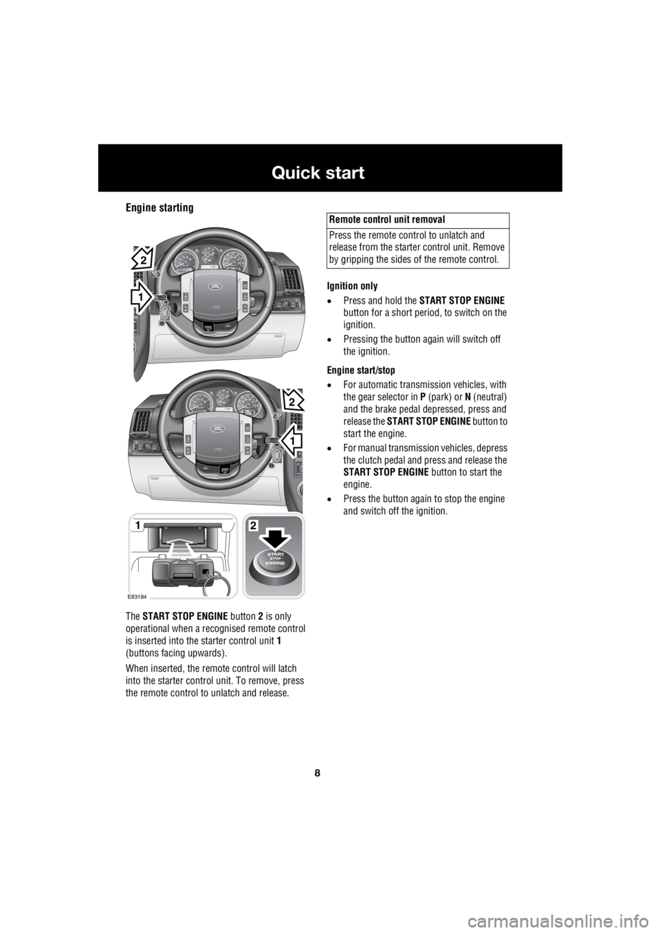
Engine starting
The START STOP ENGINE button 2 is only
operational when a rec ognised remote control
is inserted into the starter control unit 1
(buttons facing upwards).
When inserted, the remo te control will latch
into the starter control unit. To remove, press
the remote control to unlatch and release. Ignition only
• Press and hold the START STOP ENGINE
button for a short period, to switch on the
ignition.
• Pressing the button again will switch off
the ignition.
Engine start/stop
• For automatic transmission vehicles, with
the gear selector in P (park) or N (neutral)
and the brake pedal de pressed, press and
release the START STOP ENGINE button to
start the engine.
• For manual transmission vehicles, depress
the clutch pedal and press and release the
START STOP ENGINE button to start the
engine.
• Press the button again to stop the engine
and switch off the ignition.
1
EXT C23EXT F72EXT C21
EXT C23EXT F72EXT C21
1
1
2
2
E83184
2
Remote control unit removal
Press the remote control to unlatch and
release from the starter control unit. Remove
by gripping the sides of the remote control.
Page 2731 of 3229
11
Quick start
R
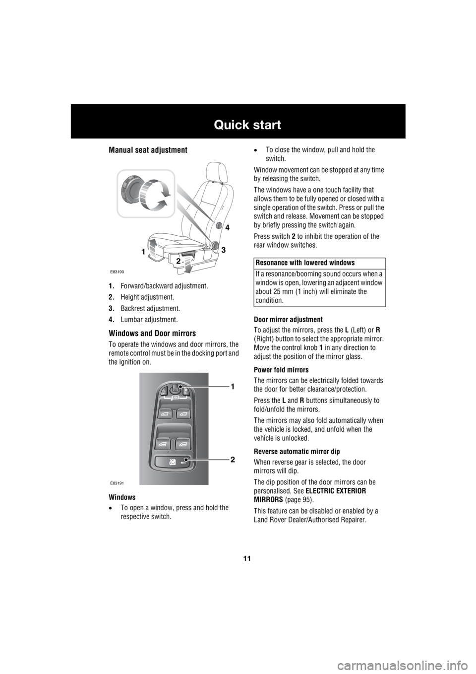
Manual seat adjustment
1. Forward/backward adjustment.
2. Height adjustment.
3. Backrest adjustment.
4. Lumbar adjustment.
Windows and Door mirrors
To operate the windows and door mirrors, the
remote control must be in the docking port and
the ignition on.
Windows
• To open a window, press and hold the
respective switch. •
To close the window, pull and hold the
switch.
Window movement can be stopped at any time
by releasing the switch.
The windows have a one touch facility that
allows them to be fully opened or closed with a
single operation of the switch. Press or pull the
switch and release. Mo vement can be stopped
by briefly pressing the switch again.
Press switch 2 to inhibit the operation of the
rear window switches.
Door mirror adjustment
To adjust the mirrors, press the L (Left) or R
(Right) button to select the appropriate mirror.
Move the control knob 1 in any direction to
adjust the position of the mirror glass.
Power fold mirrors
The mirrors can be electr ically folded towards
the door for better clearance/protection.
Press the L and R buttons simultaneously to
fold/unfold the mirrors.
The mirrors may also fold automatically when
the vehicle is locked, and unfold when the
vehicle is unlocked.
Reverse automatic mirror dip
When reverse gear is selected, the door
mirrors will dip.
The dip position of the door mirrors can be
personalised. See ELECTRIC EXTERIOR
MIRRORS (page 95).
This feature can be disabled or enabled by a
Land Rover Dealer/A uthorised Repairer.
3
2
1
E83190
4
1
2
E83191
Resonance with lowered windows
If a resonance/booming sound occurs when a
window is open, lowering an adjacent window
about 25 mm (1 inch) will eliminate the
condition.
Page 2738 of 3229
18
Quick start
L
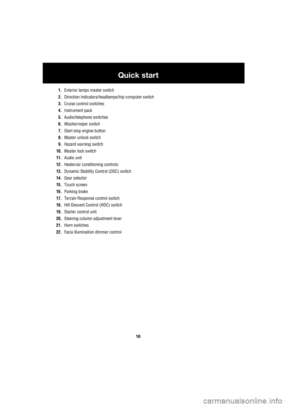
1. Exterior lamps master switch
2. Direction indicators/headlam ps/trip computer switch
3. Cruise control switches
4. Instrument pack
5. Audio/telephone switches
6. Washer/wiper switch
7. Start stop engine button
8. Master unlock switch
9. Hazard warning switch
10. Master lock switch
11. Audio unit
12. Heater/air conditioning controls
13. Dynamic Stability Control (DSC) switch
14. Gear selector
15. Touch screen
16. Parking brake
17. Terrain Response control switch
18. Hill Descent Control (HDC) switch
19. Starter control unit
20. Steering column adjustment lever
21. Horn switches
22. Facia illumination dimmer control
Page 2833 of 3229
113
Starting the engine
R
Starting the engineGENERAL INFORMATION
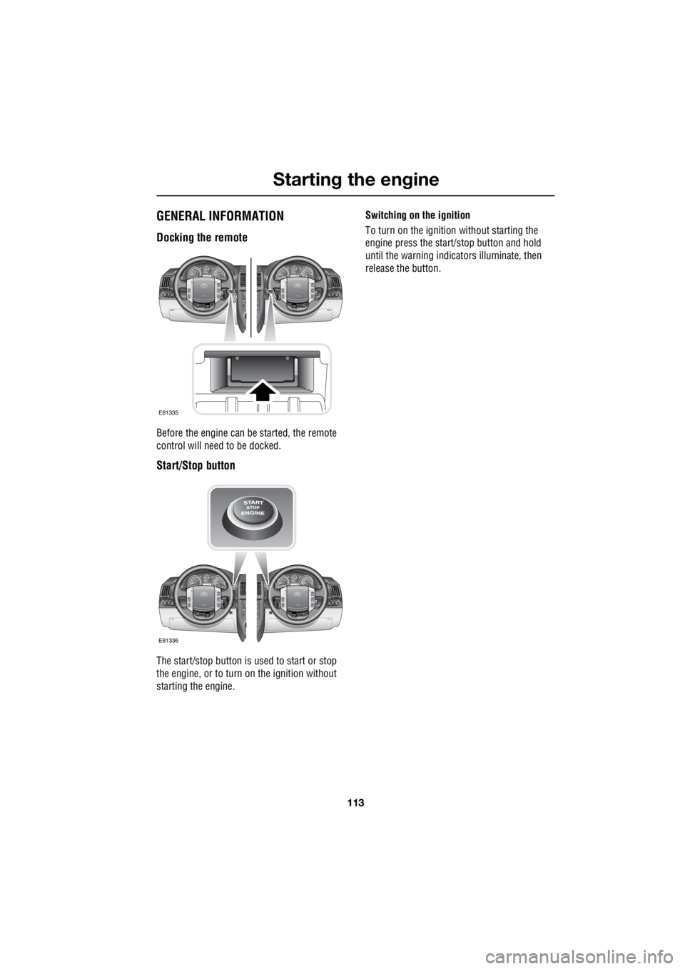
Docking the remote
Before the engine can be started, the remote
control will need to be docked.
Start/Stop button
The start/stop button is used to start or stop
the engine, or to turn on the ignition without
starting the engine. Switching on the ignition
To turn on the ignition without starting the
engine press the start/stop button and hold
until the warning indicators illuminate, then
release the button.
EXT C23EXT F72EXT C21EXT C23EXT F72EXT C21
E81335
EXT C23EXT F72EXT C21EXT C23EXT F72EXT C21
E81336
Page 2834 of 3229
Starting the engine
114
L
STARTING A PETROL ENGINE
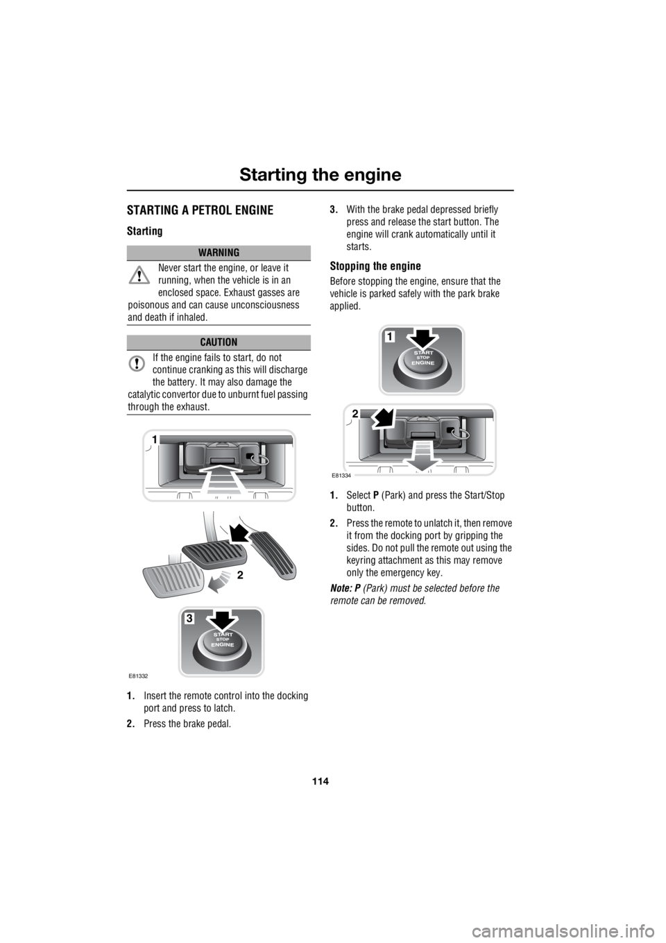
Starting
1. Insert the remote control into the docking
port and press to latch.
2. Press the brake pedal. 3.
With the brake peda l depressed briefly
press and release the start button. The
engine will crank auto matically until it
starts.
Stopping the engine
Before stopping the engine, ensure that the
vehicle is parked safely with the park brake
applied.
1. Select P (Park) and press the Start/Stop
button.
2. Press the remote to unlatch it, then remove
it from the docking port by gripping the
sides. Do not pull the remote out using the
keyring attachment as this may remove
only the emergency key.
Note: P (Park) must be selected before the
remote can be removed.
WARNING
Never start the engine, or leave it
running, when the vehicle is in an
enclosed space. Exhaust gasses are
poisonous and can cau se unconsciousness
and death if inhaled.
CAUTION
If the engine fails to start, do not
continue cranking as this will discharge
the battery. It may also damage the
catalytic conver tor due to unburnt fuel passing
through the exhaust.
3
1
2
E81332
1
2
E81334
Page 2836 of 3229
Starting the engine
116
L
Stopping the engine
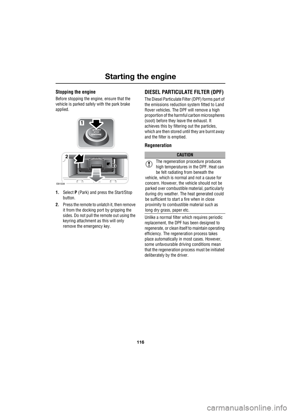
Before stopping the engine, ensure that the
vehicle is parked safely with the park brake
applied.
1. Select P (Park) and press the Start/Stop
button.
2. Press the remote to unlatch it, then remove
it from the docking port by gripping the
sides. Do not pull the remote out using the
keyring attachment as this will only
remove the emergency key.
DIESEL PARTICULATE FILTER (DPF)
The Diesel Particulate Filt er (DPF) forms part of
the emissions reduction system fitted to Land
Rover vehicles. The DPF will remove a high
proportion of the harmful carbon microspheres
(soot) before they leave the exhaust. It
achieves this by filter ing out the particles,
which are then stored until they are burnt away
and the filter is emptied.
Regeneration
Unlike a normal filter which requires periodic
replacement, the DPF has been designed to
regenerate, or clean itse lf to maintain operating
efficiency. The regene ration process takes
place automatically in most cases. However,
some unfavourable driving conditions mean
that the regeneration proc ess must be initiated
deliberately by the driver.
1
2
E81334
CAUTION
The regeneration procedure produces
high temperatures in the DPF. Heat can
be felt radiating from beneath the
vehicle, which is normal and not a cause for
concern. However, the vehicle should not be
parked over combustible material, particularly
during dry weather. The heat generated could
be sufficient to start a fire when in close
proximity to combustibl e material such as
long dry grass, paper etc.
Page 2958 of 3229
Digital audio broadcasting
238
L
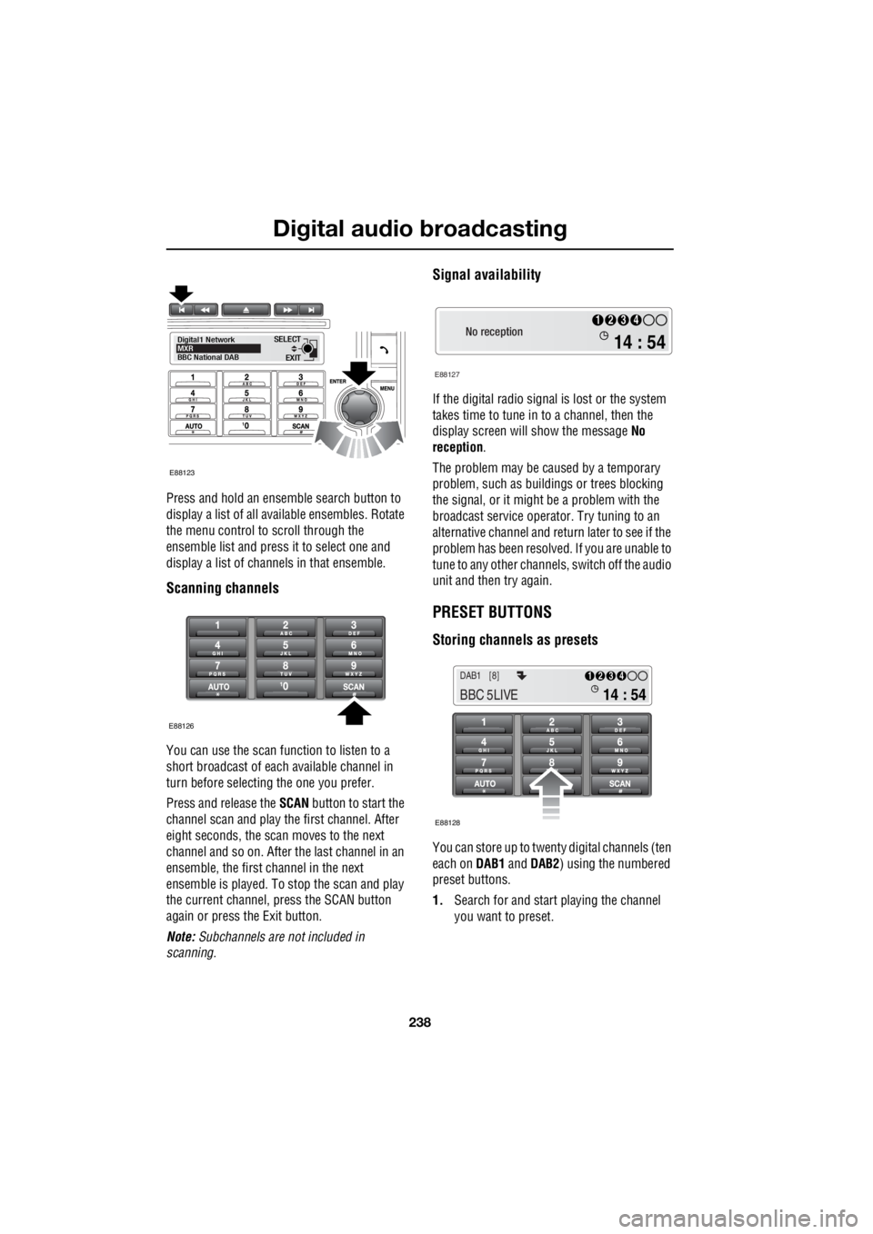
Press and hold an ensemble search button to
display a list of all available ensembles. Rotate
the menu control to scroll through the
ensemble list and press it to select one and
display a list of channels in that ensemble.
Scanning channels
You can use the scan function to listen to a
short broadcast of each available channel in
turn before selecting the one you prefer.
Press and release the SCAN button to start the
channel scan and play the first channel. After
eight seconds, the scan moves to the next
channel and so on. After the last channel in an
ensemble, the first channel in the next
ensemble is played. To stop the scan and play
the current channel, press the SCAN button
again or press the Exit button.
Note: Subchannels are not included in
scanning.
Signal availability
If the digital radio signal is lost or the system
takes time to tune in to a channel, then the
display screen will show the message No
reception .
The problem may be caused by a temporary
problem, such as buildings or trees blocking
the signal, or it might be a problem with the
broadcast service operator. Try tuning to an
alternative channel and return later to see if the
problem has been resolved. If you are unable to
tune to any other channe ls, switch off the audio
unit and then try again.
PRESET BUTTONS
Storing channels as presets
You can store up to twenty digital channels (ten
each on DAB1 and DAB2 ) using the numbered
preset buttons.
1. Search for and start playing the channel
you want to preset.
EXIT
SELECT
Digital1 Network
MXR
BBC National DAB
E88123
E88126
No reception
E88127
14 : 54
1234
14 : 54
1234DAB1 [8]
BBC 5LIVE
E88128