2006 LAND ROVER FRELANDER 2 wipers
[x] Cancel search: wipersPage 175 of 3229
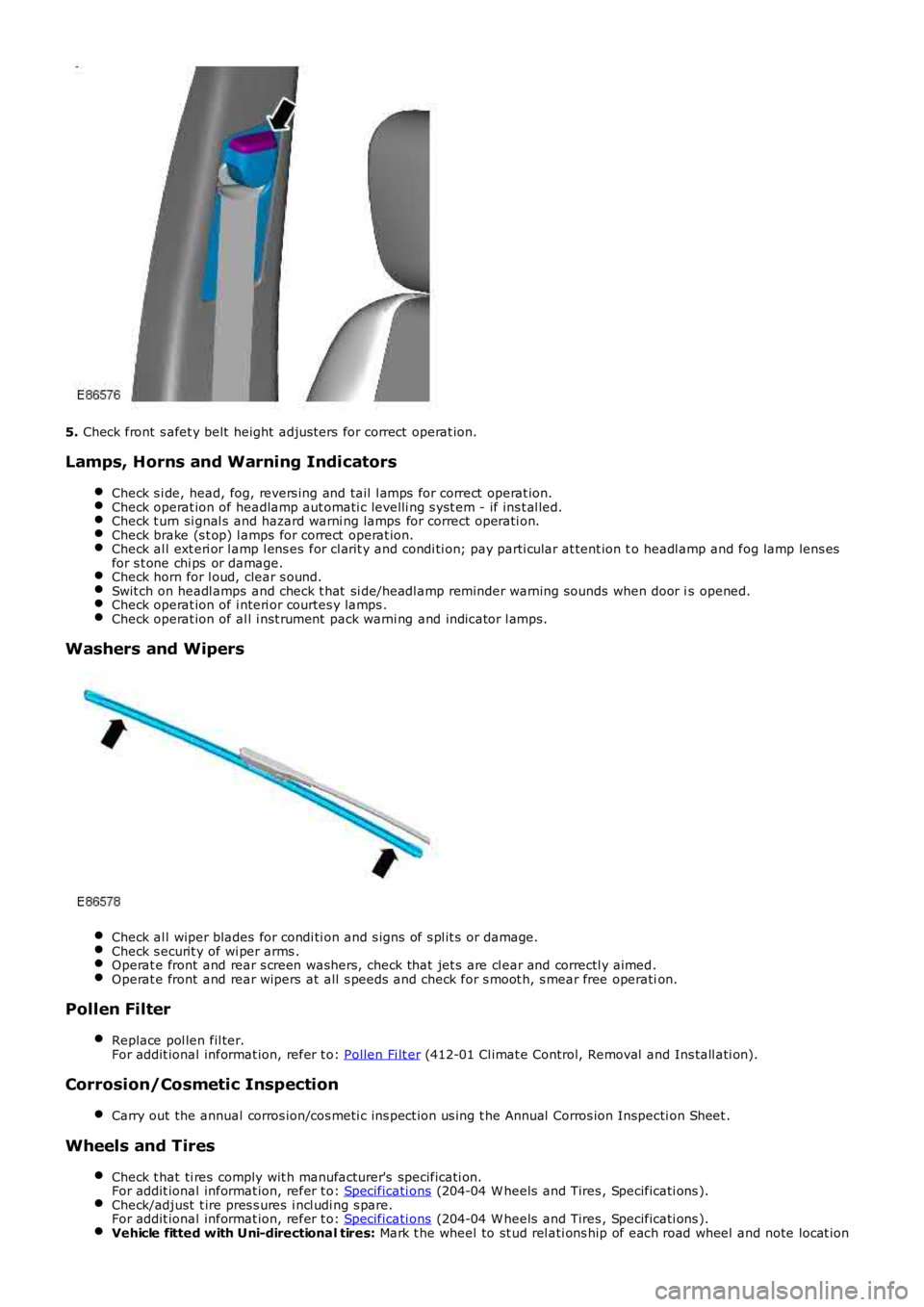
5. Check front s afet y belt height adjus ters for correct operat ion.
Lamps, Horns and Warning Indicators
Check s i de, head, fog, revers ing and tail l amps for correct operat ion.Check operat ion of headlamp aut omati c levelli ng s yst em - if ins t al led.Check t urn si gnal s and hazard warni ng lamps for correct operati on.Check brake (s t op) l amps for correct operat ion.Check al l ext eri or l amp l ens es for cl arit y and condi ti on; pay parti cular at tent ion to headl amp and fog lamp lens esfor s t one chi ps or damage.Check horn for l oud, clear s ound.Swit ch on headl amps and check t hat si de/headl amp reminder warning s ounds when door is opened.Check operat ion of i nteri or courtes y lamps .Check operat ion of al l i nst rument pack warni ng and indicator l amps.
Washers and Wipers
Check al l wiper blades for condi ti on and s igns of s pl it s or damage.Check s ecurit y of wi per arms .Operat e front and rear s creen washers, check that jet s are cl ear and correctl y aimed.Operat e front and rear wipers at all s peeds and check for s moot h, s mear free operation.
Pollen Filter
Replace pol len fil ter.For addit ional informat ion, refer t o: Pollen Fi lt er (412-01 Cl imat e Control, Removal and Ins tall ati on).
Corrosion/Cosmetic Inspection
Carry out the annual corros ion/cos meti c ins pect ion us ing t he Annual Corros ion Inspecti on Sheet .
Wheels and Tires
Check t hat ti res comply wit h manufacturer's specificati on.For addit ional informat ion, refer t o: Specificati ons (204-04 W heels and Tires , Specificati ons ).Check/adjust t ire pres s ures i ncl udi ng s pare.For addit ional informat ion, refer t o: Specificati ons (204-04 W heels and Tires , Specificati ons ).Vehicle fitted with Uni-directional tires: Mark t he wheel to st ud rel ati ons hip of each road wheel and note locat ion
Page 186 of 3229
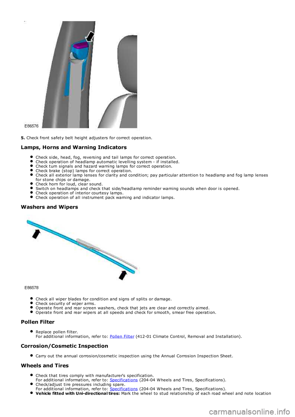
5.
Check front s afet y belt height adjus ters for correct operat ion.
Lamps, Horns and Warning Indicators Check s i de, head, fog, revers ing and tail l amps for correct operat ion. Check operat ion of headlamp aut omati c levelli ng s yst em - if ins t al led.
Check t urn si gnal s and hazard warni ng lamps for correct operati on.
Check brake (s t op) l amps for correct operat ion.
Check al l ext eri or l amp l ens es for cl arit y and condi ti on; pay parti cular at tent ion t
o headl amp and fog lamp lens es
for s t one chi ps or damage. Check horn for l oud, clear s ound.
Swit ch on headl amps and check t hat si de/headl amp reminder warning s ounds when door i
s opened.Check operat ion of i nteri or courtes y lamps .
Check operat ion of al l i nst rument pack warni ng and indicator l amps.
Washers and Wipers
Check al l wiper blades for condi ti on and s igns of s pl it s or damage.
Check s ecurit y of wi per arms .
Operat e front and rear s creen washers, check that jet s are cl ear and correctl y aimed
.Operat e front and rear wipers at all s peeds and check for s moot h, s mear free operati
on.Pollen Filter
Replace pol len fil ter.
For addit ional informat ion, refer t o: Pollen Fi lt er (412-01 Cl imat e Control, Removal and Ins tall ati on).
Corrosion/Cosmetic Inspection
Carry out the annual corros ion/cos meti c ins pect ion us ing t he Annual Corros ion Inspec ti on Sheet .Wheels and Tires
Check t hat ti res comply wit h manufacturer's specificati on.
For addit ional informat ion, refer t o: Specificati ons (204-04 W heels and Tires , Specificati ons ).
Check/adjust t ire pres s ures i ncl udi ng s pare.
For addit ional informat ion, refer t o: Specificati ons (204-04 W heels and Tires , Specificati ons ).
Vehicle fitted with Uni-directional tires:
Mark t he wheel to st ud rel ati ons hip of each road wheel and note locat ion
Page 587 of 3229
11-Int egrated audio modul e
12-Int egrated control modul e
PRINCIPLES OF OPERATION
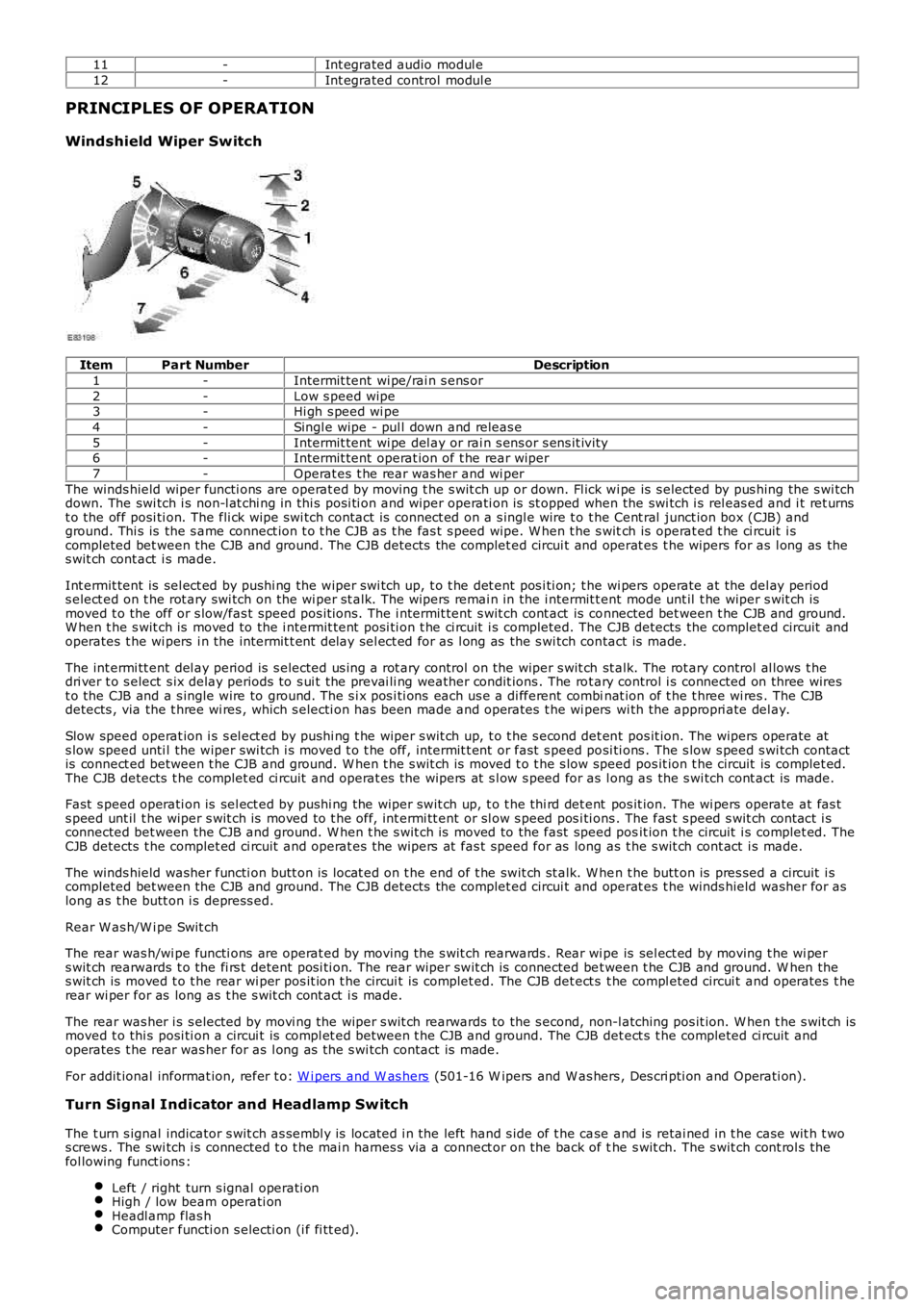
Windshield Wiper Switch
ItemPart NumberDescription
1-Intermit tent wi pe/rai n s ens or
2-Low s peed wipe3-Hi gh s peed wi pe
4-Singl e wipe - pul l down and releas e
5-Intermit tent wi pe del ay or rai n s ens or s ens it ivi ty6-Intermit tent operat ion of t he rear wiper
7-Operat es t he rear was her and wi per
The winds hield wiper functi ons are operat ed by moving t he s wit ch up or down. Fl ick wi pe is s elected by pus hing the s wi tchdown. The swi tch i s non-l at chi ng in thi s posi ti on and wiper operati on is st opped when the swi tch i s rel eas ed and i t ret urnst o the off posi ti on. The fli ck wipe s wi tch contact is connect ed on a s ingl e wire t o t he Cent ral junct ion box (CJB) andground. Thi s is the s ame connect ion t o t he CJB as t he fas t s peed wipe. W hen t he s witch is operat ed t he ci rcuit i scompleted bet ween the CJB and ground. The CJB detects the complet ed circui t and operat es t he wipers for as l ong as thes wit ch cont act i s made.
Int ermit tent is sel ect ed by pushi ng the wiper swi tch up, t o t he det ent pos i ti on; t he wi pers operate at the del ay periods elect ed on t he rot ary swi tch on the wi per st alk. The wipers remai n in the i ntermit tent mode unt il t he wiper s wit ch ismoved t o the off or s low/fas t speed pos it ions. The i ntermit tent s wit ch cont act is connected bet ween t he CJB and ground.W hen t he s wit ch is moved to the i ntermit tent posi ti on t he ci rcuit i s completed. The CJB detects the complet ed circuit andoperates t he wi pers i n the intermit t ent delay sel ect ed for as l ong as the s wi tch contact is made.
The int ermi tt ent del ay period is s elected us i ng a rot ary control on the wiper s wit ch st alk. The rot ary control al lows t hedri ver t o s elect s ix delay periods to s ui t the prevai li ng weather condit ions . The rot ary control i s connected on three wirest o the CJB and a s ingle wire to ground. The s i x pos i ti ons each us e a di fferent combinat ion of t he t hree wi res . The CJBdetects , via the t hree wi res , which s electi on has been made and operates t he wi pers wi th the appropri ate del ay.
Slow speed operat ion i s s el ect ed by pus hi ng t he wiper s wit ch up, t o t he s econd det ent pos it ion. The wipers operate ats low speed unti l the wiper swi tch i s moved t o t he off, intermit t ent or fast s peed posi ti ons . The s low s peed s wi tch contactis connect ed between t he CJB and ground. W hen t he s wit ch is moved t o t he s low speed pos it ion t he circuit is complet ed.The CJB detects t he complet ed ci rcuit and operat es the wipers at s l ow s peed for as long as the s wi tch cont act is made.
Fast s peed operati on is sel ect ed by pushi ng the wiper swit ch up, t o t he thi rd det ent pos it ion. The wi pers operate at fas ts peed unt il t he wiper s wit ch is moved to t he off, int ermi tt ent or sl ow s peed pos i ti ons . The fas t s peed s wit ch cont act i sconnected bet ween the CJB and ground. W hen t he s wit ch is moved to the fast speed posit ion t he circuit i s complet ed. TheCJB detects t he complet ed ci rcuit and operat es the wipers at fas t speed for as long as t he s wit ch cont act i s made.
The winds hield washer functi on butt on is locat ed on t he end of t he swit ch st alk. W hen t he butt on is pres sed a circuit i scompleted bet ween the CJB and ground. The CJB detects the complet ed circui t and operat es t he winds hield washer for aslong as t he butt on i s depress ed.
Rear W as h/W i pe Swit ch
The rear was h/wi pe functi ons are operat ed by moving t he s wit ch rearwards . Rear wi pe is sel ect ed by moving t he wi pers wit ch rearwards t o the fi rs t detent posi ti on. The rear wiper swit ch is connected bet ween t he CJB and ground. W hen thes wit ch is moved t o t he rear wi per pos it ion t he circui t is complet ed. The CJB det ect s t he compl eted circui t and operates t herear wi per for as long as t he s wit ch cont act i s made.
The rear was her i s s elected by movi ng the wiper s wit ch rearwards to the s econd, non-l atching pos it ion. W hen t he s wit ch ismoved t o thi s posi ti on a circui t is compl et ed between t he CJB and ground. The CJB det ect s t he completed ci rcuit andoperates t he rear was her for as l ong as the s wi tch contact is made.
For addit ional informat ion, refer t o: W i pers and W as hers (501-16 W ipers and W as hers , Des cri pti on and Operati on).
Turn Signal Indicator and Headlamp Switch
The t urn s ignal indicator s wit ch as sembl y is locat ed i n the left hand s ide of t he case and is retai ned in t he case wit h t wos crews . The swi tch i s connected t o t he mai n harnes s via a connect or on the back of the s wit ch. The s wit ch cont rol s thefol lowing funct ions :
Left / right turn s ignal operati onHigh / low beam operati onHeadl amp flas hComputer functi on s electi on (i f fi tt ed).
Page 1833 of 3229
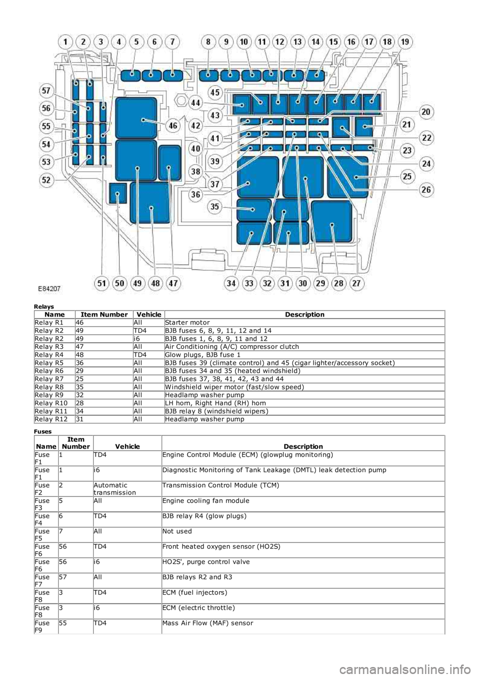
Relays
NameItem NumberVehicleDescriptionRelay R146Al lStarter mot or
Relay R249TD4BJB fus es 6, 8, 9, 11, 12 and 14
Relay R249i 6BJB fus es 1, 6, 8, 9, 11 and 12Relay R347Al lAir Condit ioning (A/C) compres s or cl utch
Relay R448TD4Glow plugs , BJB fus e 1
Relay R536Al lBJB fus es 39 (climat e control) and 45 (cigar light er/access ory socket)Relay R629Al lBJB fus es 34 and 35 (heated wi nds hiel d)
Relay R725Al lBJB fus es 37, 38, 41, 42, 43 and 44
Relay R835Al lW i ndshi el d wi per mot or (fast /sl ow s peed)Relay R932Al lHeadlamp was her pump
Relay R1028Al lLH horn, Ri ght Hand (RH) horn
Relay R1134Al lBJB rel ay 8 (winds hi eld wipers )Relay R1231Al lHeadlamp was her pump
Fuses
NameItemNumberVehicleDescription
FuseF11TD4Engine Cont rol Module (ECM) (gl owpl ug monit ori ng)
FuseF11i 6Diagnos t ic Monit ori ng of Tank Leakage (DMTL) leak det ect ion pump
FuseF22Automat ict rans mis s ionTransmis si on Control Module (TCM)
FuseF35AllEngine cooli ng fan modul e
FuseF46TD4BJB relay R4 (glow plugs)
FuseF57AllNot us ed
FuseF656TD4Front heat ed oxygen s ensor (HO2S)
FuseF656i 6HO2S', purge cont rol valve
FuseF757AllBJB relays R2 and R3
FuseF83TD4ECM (fuel injectors)
FuseF83i 6ECM (el ect ri c thrott le)
FuseF955TD4Mas s Ai r Flow (MAF) s ens or
Page 1834 of 3229
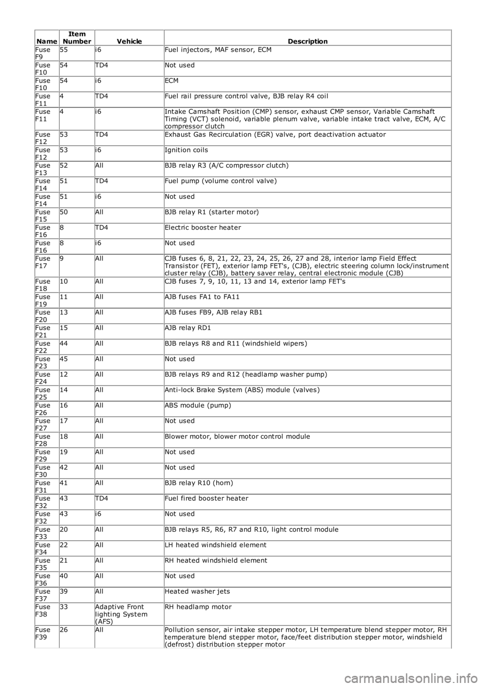
NameItemNumberVehicleDescription
FuseF955i 6Fuel inject ors , MAF s ens or, ECM
FuseF1054TD4Not us ed
FuseF1054i 6ECM
FuseF114TD4Fuel rai l press ure cont rol valve, BJB relay R4 coi l
FuseF114i 6Int ake Cams haft Pos it ion (CMP) s ens or, exhaust CMP sens or, Vari able Cams haftTi ming (VCT) s olenoi d, variable pl enum valve, variable intake t ract valve, ECM, A/Ccompres s or cl utch
FuseF1253TD4Exhaust Gas Recircul ati on (EGR) valve, port deact ivati on act uator
FuseF1253i 6Ignit ion coil s
FuseF1352AllBJB relay R3 (A/C compres sor clut ch)
FuseF1451TD4Fuel pump (vol ume cont rol valve)
FuseF1451i 6Not us ed
FuseF1550AllBJB relay R1 (s tarter mot or)
FuseF168TD4El ect ri c boos t er heat er
FuseF168i 6Not us ed
FuseF179AllCJB fus es 6, 8, 21, 22, 23, 24, 25, 26, 27 and 28, i nt eri or lamp Fi el d EffectTransi st or (FET), ext erior l amp FET's , (CJB), electric st eering col umn lock/i ns t rumentcl us t er relay (CJB), batt ery s aver relay, cent ral electronic module (CJB)
FuseF1810AllCJB fus es 7, 9, 10, 11, 13 and 14, ext erior l amp FET's
FuseF1911AllAJB fus es FA1 to FA11
FuseF2013AllAJB fus es FB9, AJB rel ay RB1
FuseF2115AllAJB relay RD1
FuseF2244AllBJB relays R8 and R11 (winds hield wipers )
FuseF2345AllNot us ed
FuseF2412AllBJB relays R9 and R12 (headl amp was her pump)
FuseF2514AllAnt i-lock Brake Sys tem (ABS) module (valves )
FuseF2616AllABS modul e (pump)
FuseF2717AllNot us ed
FuseF2818AllBl ower motor, bl ower motor cont rol module
FuseF2919AllNot us ed
FuseF3042AllNot us ed
FuseF3141AllBJB relay R10 (horn)
FuseF3243TD4Fuel fi red boos ter heater
FuseF3243i 6Not us ed
FuseF3320AllBJB relays R5, R6, R7 and R10, l ight cont rol module
FuseF3422AllLH heat ed wi nds hield element
FuseF3521AllRH heat ed wi nds hiel d element
FuseF3640AllNot us ed
FuseF3739AllHeat ed was her jets
FuseF3833Adapti ve Frontl ighti ng Sys t em(AFS)
RH headl amp mot or
FuseF3926AllPol luti on s ens or, ai r int ake st epper mot or, LH t emperat ure bl end st epper mot or, RHtemperat ure bl end st epper mot or, face/feet dis t ri but ion s t epper mot or, wi nds hield(defrost ) dis t ri but ion s t epper mot or
Page 1922 of 3229
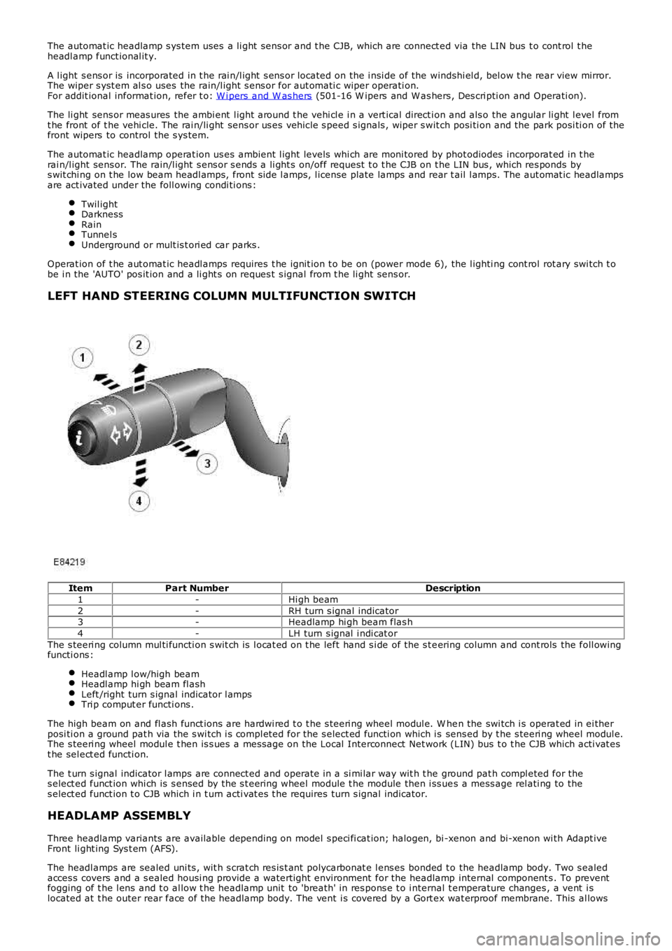
The automat ic headlamp s ys tem uses a li ght s ens or and t he CJB, which are connect ed via the LIN bus t o cont rol t heheadl amp funct ional it y.
A l ight s ens or is incorporated in t he rai n/l ight s ens or located on the i nsi de of the windshi el d, bel ow t he rear view mirror.The wiper s yst em al s o uses the rain/l ight s ens or for aut omati c wiper operati on.For addit ional informat ion, refer t o: W i pers and W as hers (501-16 W ipers and W as hers , Des cri pti on and Operati on).
The li ght sens or meas ures the ambi ent l ight around t he vehi cl e i n a vert ical direct ion and als o the angular li ght l evel fromt he front of t he vehi cle. The rai n/li ght sens or us es vehicle s peed s ignals , wiper s wit ch posi ti on and the park posi ti on of thefront wipers to control the s ys tem.
The automat ic headlamp operat ion us es ambient l ight levels whi ch are moni tored by phot odiodes incorporat ed in t herai n/l ight sens or. The rain/l ight s ens or s ends a li ght s on/off request t o t he CJB on t he LIN bus , which res ponds bys wit chi ng on t he low beam headl amps, front s ide l amps, l icense plate lamps and rear t ail l amps. The aut omat ic headlampsare act ivated under the foll owing condi ti ons :
Twil ightDarknessRainTunnel sUnderground or mult is t ori ed car parks .
Operat ion of t he aut omat ic headl amps requires t he ignit ion t o be on (power mode 6), the l ighti ng cont rol rot ary swi tch t obe i n the 'AUTO' pos it ion and a li ght s on reques t s ignal from t he li ght sens or.
LEFT HAND STEERING COLUMN MULTIFUNCTION SWITCH
ItemPart NumberDescription
1-Hi gh beam
2-RH turn s ignal indicator3-Headlamp hi gh beam flas h
4-LH turn s ignal i ndi cat or
The s teeri ng column mul ti functi on s wit ch is l ocat ed on t he left hand s i de of the s t eering column and cont rols the foll owingfuncti ons :
Headl amp l ow/high beamHeadl amp hi gh beam fl ashLeft /right turn s ignal indicator l ampsTri p comput er functi ons .
The high beam on and fl ash funct ions are hardwi red t o t he s teeri ng wheel modul e. W hen the swi tch i s operat ed in ei therposi ti on a ground pat h via the s wi tch i s compl eted for the s elect ed functi on which is sens ed by t he s teeri ng wheel modul e.The s teeri ng wheel modul e t hen is s ues a mes sage on the Local Interconnect Net work (LIN) bus t o t he CJB which acti vat est he sel ect ed functi on.
The t urn s ignal indicator l amps are connect ed and operate in a si mi lar way wit h t he ground pat h compl eted for thes elect ed funct ion whi ch is s ensed by the s t eering wheel module t he module then i ss ues a mess age rel ati ng to thes elect ed funct ion t o CJB which i n t urn acti vat es t he requires turn s ignal indicator.
HEADLAMP ASSEMBLY
Three headlamp variants are available depending on model s peci fi cat ion; halogen, bi -xenon and bi-xenon wi th Adapt iveFront li ght ing Sys t em (AFS).
The headl amps are sealed uni ts , wit h s crat ch res is t ant polycarbonat e l ens es bonded to the headlamp body. Two s ealedacces s covers and a s ealed housi ng provide a waterti ght environment for the headlamp internal component s . To preventfogging of t he l ens and t o al low t he headlamp unit to 'breath' in res pons e t o i nternal t emperature changes , a vent i slocated at t he outer rear face of the headlamp body. The vent i s covered by a Gort ex wat erproof membrane. This al lows
Page 2344 of 3229
Publi s hed: 11-May-2011
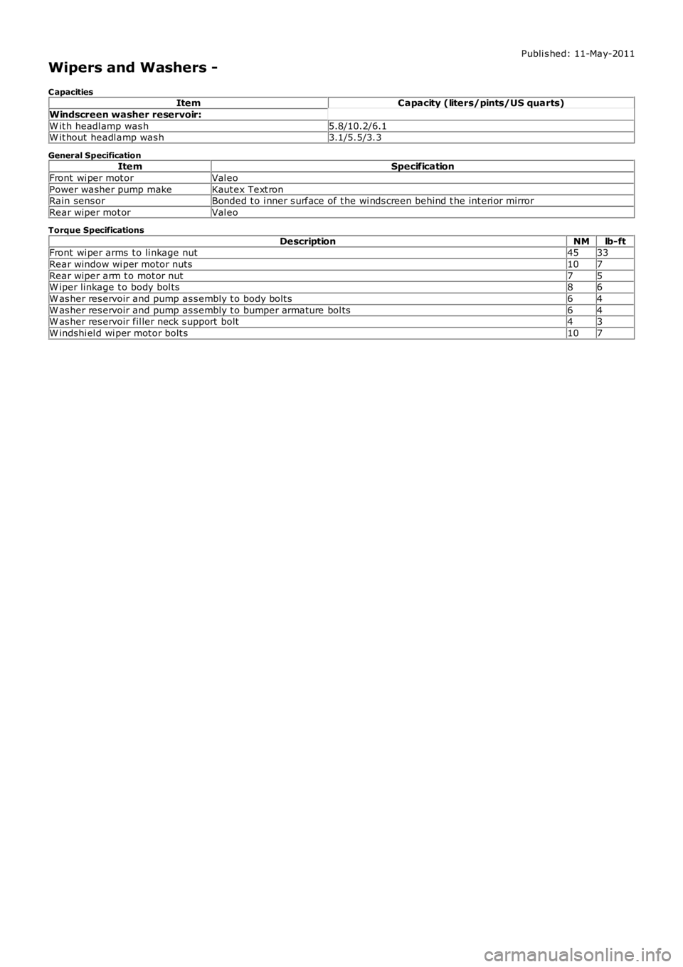
Wipers and Washers -
C apacitiesItemCapacity (liters/pints/US quarts)
Windscreen washer reservoir:
W it h headl amp was h5.8/10.2/6.1W it hout headl amp was h3.1/5.5/3.3
General SpecificationItemSpecification
Front wi per mot orVal eo
Power washer pump makeKaut ex Text ronRain sens orBonded t o i nner s urface of t he wi nds creen behind t he int eri or mirror
Rear wiper mot orVal eo
Torque Specifications
DescriptionNMlb-ftFront wi per arms t o li nkage nut4533
Rear window wi per motor nuts107
Rear wiper arm t o mot or nut75W iper linkage t o body bol ts86
W as her res ervoir and pump as s embly t o body bolt s64
W as her res ervoir and pump as s embly t o bumper armat ure bol ts64W as her res ervoir fil ler neck s upport bolt43
W indshi el d wi per mot or bolt s107
Page 2345 of 3229
Publi s hed: 11-May-2011
Wipers and Washers - Wipers and Washers
Des cript ion and Operat ion
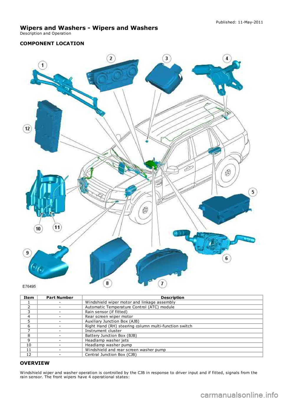
COMPONENT LOCATION
ItemPart NumberDescription1-W i nds hiel d wiper mot or and linkage as sembl y
2-Automat ic Temperat ure Cont rol (ATC) module
3-Rain s ens or (if fit ted)4-Rear s creen wi per motor
5-Auxi li ary Junct ion Box (AJB)
6-Right Hand (RH) st eering col umn mult i-functi on s wit ch7-Ins t rument clus ter
8-Batt ery Junct ion Box (BJB)
9-Headl amp was her jets10-Headl amp was her pump
11-W i nds hiel d and rear s creen was her pump
12-Cent ral Junct ion Box (CJB)
OVERVIEW
W i nds hiel d wi per and was her operat ion is control led by the CJB i n res ponse to driver input and if fit ted, s ignals from t herai n s ens or. The front wi pers have 4 operat ional st ates :