2006 LAND ROVER FRELANDER 2 headlamp
[x] Cancel search: headlampPage 21 of 3229
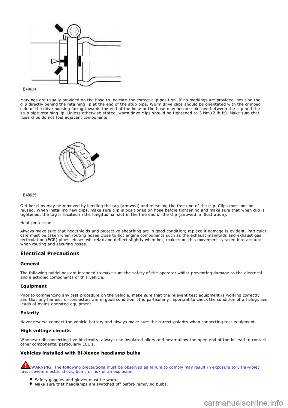
Marki ngs are us ual ly provi ded on t he hos e t o i ndi cat e t he correct cli p posi ti on. If no markings are provi ded, pos it ion t heclip direct ly behind t he ret aini ng li p at the end of t he s tub pi pe. W orm dri ve clips s hould be orient at ed wi th the crimpeds ide of t he dri ve hous ing facing t owards t he end of the hos e or t he hos e may become pi nched bet ween the cli p and t hes tub pi pe ret aining l ip. Unles s ot herwis e s t ated, worm dri ve cl ips s hould be ti ght ened to 3 Nm (2 lb-ft). Make s ure t hathose cl ips do not foul adjacent components .
Oeti ker cl ips may be removed by bendi ng the tag (arrowed) and releas ing t he free end of t he cl ip. Cli ps mus t not bereus ed. W hen ins t al li ng new cli ps , make s ure cl ip is pos it ioned on hose before ti ghtening and make s ure that when cli p ist ightened, the t ag is locat ed i n t he longit udi nal s lot i n t he free end of the cl ip (arrowed in il lus trat ion).
Heat protect ion
Always make s ure that heats hields and protecti ve s heat hing are in good condit ion; replace i f damage i s evident. Part icularcare mus t be t aken when rout ing hos es cl ose to hot engine component s s uch as the exhaust mani fol ds and exhaust gasrecircul ati on (EGR) pipes . Hoses will relax and defl ect s l ightl y when hot, make s ure thi s movement is t aken into accountwhen rout ing and s ecuring hos es .
Electrical Precautions
General
The fol lowing gui del ines are int ended t o make s ure the safet y of t he operator whil s t prevent ing damage t o t he electricaland electroni c component s of this vehi cl e.
Equipment
Pri or to commencing any t est procedure on the vehicl e, make sure t hat t he rel evant test equipment i s working correctl yand t hat any harnes s or connectors are i n good condi ti on. It is parti cul arly import ant to check t he condit ion of al l pl ugs andleads of mains operat ed equipment.
Polarity
Never revers e connect the vehicle bat tery and always make s ure the correct pol arit y when connect ing t est equipment .
High voltage circuits
W henever di sconnect ing l ive ht circuit s , always us e ins ulat ed pliers and never all ow t he open end of the ht l ead to cont actother component s, part icularly ECU's .
Vehicles installed with Bi-Xenon headlamp bulbs
W ARNING: The foll owing precauti ons mus t be obs erved as fail ure t o comply may res ult i n expos ure to ul tra-vi ol etrays , s evere electric s hock, burns or ris k of an expl osi on.
Safet y goggl es and gl oves must be worn.Make s ure t hat headlamps are s wi tched off before removi ng bul bs.
Page 22 of 3229
Do not t ouch t he glas s port ion of t he bulb.On no account s hould headlamps be s wi tched on wi th t he bulb removed from the headlamp.Bulb t es ti ng may only be carri ed out wit h the bul b ins t al led i n t he headl amp.Bulbs mus t be di spos ed of in accordance wit h the local aut horit y bye-laws .
Connectors and harnesses
The engi ne compart ment of a vehi cl e is a part icularl y host il e environment for el ect ri cal component s and connectors. Al waysobserve the foll owing:
Make s ure el ect ri cal ly related it ems are dry and oil free before di sconnect ing/connecti ng t es t equipment .Make s ure t hat dis connect ed mul ti pl ugs and s ens ors are prot ect ed from any pos s ibl e oil , coolant or other li qui dcont aminat ion. Any such contami nat ion could impair performance or l ead to component fail ure.Never force connectors apart or pull on t he wiring harnes s .Always make s ure locki ng t abs are dis engaged before di sconnect ing mul ti plugs etc. and make s ure that correctori ent ati on is achieved before connecti on.Make s ure t hat any protecti on covers, i nsul at ion et c. are replaced if dis t urbed.
Having confirmed t hat a component is fault y, carry out t he fol lowing:
Swit ch off t he ignit ion and di s connect t he batt ery.Remove the component and support t he dis connected harnes s .W hen replaci ng electrical components , keep oily hands away from electrical connect ions and make s ure that lockingt abs on connect ors are ful ly engaged.
Battery Disconnection/Connection
Always refer to the El ect ri cal Secti on of this manual - Bat tery Connecti on/Dis connecti on pri or t o at tempt ing t o connect ordis connect the bat tery.For addit ional informat ion, refer t o: Specificati ons (414-01 Bat t ery, Mount ing and Cables , Speci ficat ions).
Fuel Handling Precautions
The fol lowing informati on li s ts bas ic precauti ons which mus t be obs erved if fuel i s t o be handl ed s afely. It als o outl inesother areas of ris k which mus t not be i gnored. As t his informati on is is sued for basi c gui dance only, consul t your local Fi reDepart ment where any doubt as to personal and envi ronmental s afet y exi s ts - See al so Heal th and Safety Precaut ions .
General precaut ions
Always have t he correct type of fire ext inguis her cont aining Foam, CO2, Gas or powder acces s ible when handl ing ordrai ni ng fuel or dis mantl ing fuel s ys tems . Fire exti ngui shers mus t als o be l ocat ed in areas where fuel i s s tored.
Make s ure t hat sui table warning si gns are exhibit ed.
Keep all s ources of ignit ion wel l away from areas where fuel is bei ng handl ed.
Make s ure t hat any leadlamps are fl ameproof and kept clear of spi ll age.
• W ARNINGS:
Do not di sas s emble or reas s emble fuel sys tem components whils t vehicle is over a pit .
No one should be permi tt ed to repair component s as sociat ed wit h fuel wi thout fi rs t having s peci alis t t rai ni ng.
Always dis connect t he vehi cl e batt ery before carryi ng out dis ass embly, reas s embly or drai ning work on a fuel sys tem.
Fuel t ank and s ys t em drai ning
Drai ning mus t be carried out in accordance wit h t he procedures given in the relevant Fuel Syst em s ecti on of thi s manual .
• W ARNINGS:
Never drain fuel or work on a fuel sys t em whil e t he vehi cl e i s over a pi t. Ext raction or draining of fuel must becarri ed out in a well venti lated area.
Al ways at tach fuel vapor warning l abel s t o fuel t anks i mmediat ely after drai ni ng.
Contai ners us ed for s toring fuel must be cl early marked wit h t he cont ents and pl aced i n a safe s torage area whichmeets the requi rement s of the local authorit y.
CAUTION: Some fuel l ines are now i ns t alled wit h 'quick release' connectors. If a connect or i s damaged, no at t emptmus t be made t o repai r the connect or, a new fuel line and connect or(s ) as s embly must be ins tall ed.
Always release pipe cli ps full y before att empti ng t o dis connect fuel pipes.
Fuel tank repairs
CAUTION: No at tempt s hould be made to repair a pl ast ic fuel tank. If t he s truct ure of t he t ank is damaged, a new
Page 75 of 3229
DT CDescriptionPossible CauseAction
B1D17-88Batt ery BackedSounder - bus offLos t communicat ions wi thbat tery backed s ounderCarry out the net work t est as s oci ated wi th thi s DTCusi ng t he manufact urer approved diagnost ic s ys tem
B1D17-96Batt ery BackedSounder - componentint ernal fai lure
Bat tery backed s ounder -i nternal failureIns t al l a new bat tery backed s ounder, refer t o newmodule/component i nst all at ion not e at t he top of t heDTC IndexB1D18-96Volumet ri c Sens orCircui t - componentint ernal fai lure
Interior mot ion s ensor -i nternal failureIns t al l a new i nteri or moti on s ens or, refer t o newmodule/component i nst all at ion not e at t he top of t heDTC Index
B1D21-62Remote Cont rolSwit ch - Signalcompare failure
A request from aprogrammed remote keywas recei ved and theroll ing count er wasi ncorrect
Re-s ynchroni se the remote key by us i ng the key t os tart the vehicle
B1C55-12Horn Rel ay CoilCircui t - circuit shortt o power
Horn rel ay cont rol circui t -s hort t o powerRefer to electrical ci rcuit diagrams and check horn relaycont rol circuit for s hort to power
B1C55-14Horn Rel ay CoilCircui t- ci rcuit s hortt o ground or open
Horn rel ay cont rol circui t -s hort t o ground, openci rcuit
Refer to electrical ci rcuit diagrams and check horn relaycont rol circuit for s hort to ground, open circui t
B1C82-12Headlamp W asherRelay Coil Ci rcuit -circui t short to power
Headlamp washer rel aycontrol ci rcuit - s hort t opower
Refer to electrical ci rcuit diagrams and check headl ampwasher rel ay cont rol circui t for s hort t o power
B1C82-14Headlamp W asherRelay Coil Ci rcuit -circui t short to groundor open
Headlamp washer rel aycontrol ci rcuit - s hort t oground, open circuit
Refer to electrical ci rcuit diagrams and check headl ampwasher rel ay cont rol circui t for s hort t o ground, openci rcuit
B1C84-12Heated Rear W i ndowRelay Out put Ci rcuit -circui t short to power
Heat ed rear wi ndow relaycontrol ci rcuit - s hort t opower
Refer to electrical ci rcuit diagrams and check heatedrear window relay control ci rcuit for s hort t o power
B1C84-14Heated Rear W i ndowRelay Out put Ci rcuit -circui t short to groundor open
Heat ed rear wi ndow relaycontrol ci rcuit - s hort t oground, open circuit
Refer to electrical ci rcuit diagrams and check heatedrear window relay control ci rcuit for s hort t o ground,open ci rcuit
B1C90-12Auxili ary DrivingLamps Relay CoilCircui t - circuit shortt o power
Auxil iary dri vi ng lampsrelay control ci rcuit - s hortt o power
Refer to electrical ci rcuit diagrams and check auxi li arydri vi ng lamps relay control ci rcuit for s hort t o power
B1C90-14Auxili ary DrivingLamps Relay CoilCircui t - circuit shortt o ground or open
Auxil iary dri vi ng lampsrelay control ci rcuit - s hortt o ground, open circuit
Refer to electrical ci rcuit diagrams and check auxi li arydri vi ng lamps relay control ci rcuit for s hort t o ground,open ci rcuit
B1D13-12Int eri or Li ght s #1Circui t - circuit shortt o power
Ins trument panel int eriorl ight s ci rcuit - s hort t opower
Refer to electrical ci rcuit diagrams and checkins trument panel int eri or l ights ci rcuit for short topower
B1D13-14Int eri or Li ght s #1Circui t - circuit shortt o ground or open
Ins trument panel int eriorl ight s ci rcuit - s hort t oground, open circuit
Refer to electrical ci rcuit diagrams and checkins trument panel int eri or l ights ci rcuit for short toground, open circui t
B1D1A-12Int eri or Li ght s Ci rcuit'C' - circui t s hort topower
Roof cons ole int erior l ightsci rcuit - s hort t o powerRefer to electrical ci rcuit diagrams and check roof panelint erior l ights ci rcuit for s hort t o power
B1D1A-14Int eri or Li ght s Ci rcuit'C' - circui t s hort toground or open
Roof cons ole int erior l ightsci rcuit - s hort t o ground,open circui t
Refer to electrical ci rcuit diagrams and check roof panelint erior l ights ci rcuit for s hort t o ground, open circuit
B1D35-24Hazard Swi tch -Signal st uck highHazard swit ch is acti vemore t han 60 s econdsCarry out the pi npoint t es ts as s oci at ed t o t his DTCusi ng t he manufact urer approved diagnost ic s ys tem
C0023-11Stop Lamp Cont rol -circui t short to groundSt op lamp cont rol circui t -s hort t o groundRefer to electrical ci rcuit diagrams and check s top lampcont rol circuit for s hort to ground
C0023-13Stop Lamp Cont rol -circui t openSt op lamp cont rol circui t -open circui tRefer to electrical ci rcuit diagrams and check s top lampcont rol circuit for open ci rcuit
C1108-11Pedal Sens or(s )Suppl y Volt age -circui t short to ground
Pedal sens or(s ) supplyvolt age circui t - short toground
Refer to electrical ci rcuit diagrams and check pedals ens or(s ) supply vol tage circui t for s hort t o ground
C1108-15Pedal Sens or(s )Suppl y Volt age -circui t short to poweror open
Pedal sens or(s ) supplyvolt age circui t - short topower, open circui t
Refer to electrical ci rcuit diagrams and check pedals ens or(s ) supply vol tage circui t for s hort t o power,open ci rcuit
C1A41-21Clut ch Pedal Sensor -s ignal amplit ude
Page 77 of 3229
DT CDescriptionPossible CauseAction
C1A63-13Right Rear Ini ti at or -open circuitRi ght rear init iat or ci rcuit -open circui tRefer to electrical ci rcuit diagrams and check right rearinit iat or ci rcuit for open ci rcuit
C1B14-12Sensor s uppl y #1 -circui t short to powerSens or supply #1 circuit -s hort t o powerRefer to electrical ci rcuit diagrams and check s ens ors upply #1 circui t for s hort t o power
C1D18-00Local is ati on fail edTi re press ure monit orl ocal is ati on fai ledCheck for addi ti onal rel ated DTCs and refer t o thi s DTCIndex
C1D21-05W heel module -general si gnal failureSi emens int ernal al gorit hmCarry out the pi npoint t es ts as s oci at ed t o t his DTCusi ng t he manufact urer approved diagnost ic s ys tem
C1D22-49Steering W heelSwit ch Right Module -Int ernal fai lure
St eering wheel s wit ch ri ghtmodul e - int ernal fai lureIns t al l a new was h/wi pe s wit ch, refer t o newmodule/component i nst all at ion not e at t he top of t heDTC IndexC2003-07Steering W heelSwit ch Left Module -Mechani cal Failures
St eering wheel s wit ch leftmodul e - mechani calfail ure
Ins t al l a new i ndi cat or swit ch, refer to newmodule/component i nst all at ion not e at t he top of t heDTC Index
C2003-49Steering W heelSwit ch Left Module -Int ernal fai lure
St eering wheel s wit ch leftmodul e - int ernal fai lureIns t al l a new i ndi cat or swit ch, refer to newmodule/component i nst all at ion not e at t he top of t heDTC Index
C2004-12Headlamp was herrel ay B - circui t s hortt o power
Headlamp washer rel ay Bci rcuit - s hort t o powerRefer to electrical ci rcuit diagrams and check headl ampwasher rel ay B circui t for s hort t o power
C2004-14Headlamp was herrel ay B - circui t s hortt o ground or open
Headlamp washer rel ay Bci rcuit - s hort t o ground,open circui t
Refer to electrical ci rcuit diagrams and check headl ampwasher rel ay B circui t for s hort t o ground, open ci rcuit
P0460-15Fuel Level Sens or A -s hort t o batt ery oropen circuit
Fuel tank unit ci rcuit As hort t o power, openci rcuit
• NOTE: Carry out pi npoi nt tes ts ass ociated wit h t hi sDTC us ing t he manufacturer approved diagnos ti cs ys t em
Refer to the el ect ri cal circui t diagrams and check theci rcuit bet ween the central junct ion box and the fueltank unit ci rcuit (F/P s ensor) for s hort t o power, openci rcuit . Us ing t he manufacturer approved diagnos ti cs ys t em check and i nst all l at es t relevant level ofs oftware t o t he cent ral juncti on box and t he ins trumentpanel clus ter. If t he level of software is correct carryout a batt ery reset
P0462-00Fuel Level Sens or A -no s ubtypeinformat ion
Fuel tank unit ci rcuit As hort t o ground or hi ghres is tance
• NOTE: Carry out pi npoi nt tes ts ass ociated wit h t hi sDTC us ing t he manufacturer approved diagnos ti cs ys t em
Refer to the el ect ri cal circui t diagrams and check theci rcuit bet ween the central junct ion box and the fueltank unit ci rcuit (F/P s ensor) for s hort t o ground. Us ingthe manufact urer approved diagnos t ic s ys tem checkand ins tal l lates t rel evant l evel of software t o t hecent ral juncti on box and the ins trument panel cl ust er.If t he l evel of software i s correct carry out a bat t eryres et
P0604-00Int ernal ControlModule RandomAcces s Memory (RAM)Error
RAM Checks um not correctIns t al l a new CJB, refer t o t he new module/componentins tal lati on note at the t op of the DTC Index
P0605-00Int ernal ControlModule Read Onl yMemory (ROM) Error
ROM Checks um not correctIns t al l a new CJB, refer t o t he new module/componentins tal lati on note at the t op of the DTC Index
P062F-00Int ernal ControlModule Read Onl yMemory (ROM) Error
EEP read back val ue doesnot mat ch wri tt en valueIns t al l a new CJB, refer t o t he new module/componentins tal lati on note at the t op of the DTC Index
P0801-11Revers e inhibi tcont rol circui t - circuits hort t o ground
Revers e i nhi bit controlci rcuit - s hort t o groundRefer to electrical ci rcuit diagrams and check revers einhibi t cont rol ci rcuit for short to ground
P1346-13Fuel Level Sens or B -open circuitFuel tank unit ci rcuit Bs hort t o power, openci rcuit
• NOTE: Carry out pi npoi nt tes ts ass ociated wit h t hi sDTC us ing t he manufacturer approved diagnos ti cs ys t em
Refer to the el ect ri cal circui t diagrams and check theci rcuit bet ween the central junct ion box and the fueltank unit ci rcuit (Fuel eject s ens or) for s hort to power,open ci rcuit . Usi ng t he manufacturer approveddiagnos t ic s ys tem check and ins t al l lat es t relevantlevel of s oft ware to the central junct ion box and theins trument panel clus ter. If t he level of s oftware iscorrect carry out a bat t ery res et
P1348-00Fuel Level Sens or B -no s ubtypeinformat ion
Fuel tank unit ci rcuit Bs hort t o ground• NOTE: Carry out pi npoi nt tes ts ass ociated wit h t hi sDTC us ing t he manufacturer approved diagnos ti cs ys t em
Refer to the el ect ri cal circui t diagrams and check theci rcuit bet ween the central junct ion box and the fuel
Page 78 of 3229
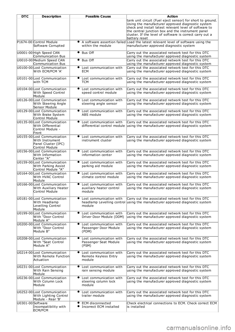
DT CDescriptionPossible CauseAction
tank unit ci rcuit (Fuel eject s ens or) for s hort to ground.Us ing t he manufacturer approved diagnost ic sys temcheck and ins t al l lat es t relevant l evel of s oft ware t othe central juncti on box and the i nst rument panelcl ust er. If t he level of s oft ware is correct carry out abat t ery resetP1674-00Control ModuleSoft ware Corrupt edA s oft ware as s ert ion fai ledwit hi n t he moduleLoad the l ates t rel evant level of s oftware usi ng t hemanufacturer approved diagnost ic sys tem
U0001-00High Speed CANCommunicati on BusBus O ffCarry out the as s oci at ed network t es t for this DTCusi ng t he manufact urer approved diagnost ic s ys tem
U0010-00Medium Speed CANCommunicati on BusBus O ffCarry out the as s oci at ed network t es t for this DTCusi ng t he manufact urer approved diagnost ic s ys tem
U0100-00Lost Communi cat ionW i th ECM/PCM 'A'Los t communicat ion wit hECMCarry out the as s oci at ed network t es t for this DTCusi ng t he manufact urer approved diagnost ic s ys tem
U0101-00Lost Communi cat ionwi th TCMLos t communicat ion wit hTCMCarry out the as s oci at ed network t es t for this DTCusi ng t he manufact urer approved diagnost ic s ys tem
U0104-00Lost Communi cat ionW i th Speed Cont rolModule
Los t communicat ion wit hs peed cont rol moduleCarry out the as s oci at ed network t es t for this DTCusi ng t he manufact urer approved diagnost ic s ys tem
U0126-00Lost Communi cat ionW i th Steeri ng AngleSensor Module
Los t communicat ion wit hs t eering angle s ens orCarry out the as s oci at ed network t es t for this DTCusi ng t he manufact urer approved diagnost ic s ys tem
U0129-00Lost Communi cat ionW i th Brake Syst emControl Module
Los t communicat ion wit hABS modul eCarry out the as s oci at ed network t es t for this DTCusi ng t he manufact urer approved diagnost ic s ys tem
U0135-00Lost Communi cat ionW i th Different ialControl Module -Front
Los t communicat ion wit hdi fferenti al control modul eCarry out the as s oci at ed network t es t for this DTCusi ng t he manufact urer approved diagnost ic s ys tem
U0155-00Lost Communi cat ionW i th Ins t rumentPanel Cl us t er (IPC)Control Module
Los t communicat ion wit hi nst rument clus t erCarry out the as s oci at ed network t es t for this DTCusi ng t he manufact urer approved diagnost ic s ys tem
U0156-00Lost Communi cat ionW i th Informat ionCenter "A"
Los t communicat ion wit hi nformati on cent erCarry out the as s oci at ed network t es t for this DTCusi ng t he manufact urer approved diagnost ic s ys tem
U0159-00Lost Communi cat ionW i th Parking As s is tControl Module "A"
Los t communicat ion wit hparki ng aid modul eCarry out the as s oci at ed network t es t for this DTCusi ng t he manufact urer approved diagnost ic s ys tem
U0164-00Lost Communi cat ionW i th HVAC ControlModule
Los t communicat ion wit hcl imat e cont rol moduleCarry out the as s oci at ed network t es t for this DTCusi ng t he manufact urer approved diagnost ic s ys tem
U0166-00Lost Communi cat ionW i th Auxi li ary HeaterControl Module
Los t communicat ion wit hauxil iary heat er cont rolmodul e
Carry out the as s oci at ed network t es t for this DTCusi ng t he manufact urer approved diagnost ic s ys tem
U0181-00Lost Communi cat ionW i th Headl ampLevel ling Cont rolModule
Los t communicat ion wit hheadlamp Levell ing controlmodul e
Carry out the as s oci at ed network t es t for this DTCusi ng t he manufact urer approved diagnost ic s ys tem
U0199-00Lost Communi cat ionW i th "Door ControlModule A"
Los t communicat ion wit hDriver Door Modul e (DDM)Carry out the as s oci at ed network t es t for this DTCusi ng t he manufact urer approved diagnost ic s ys tem
U0200-00Lost Communi cat ionW i th "Door ControlModule B"
Los t communicat ion wit hPas s enger Door Modul e(PDM)
Carry out the as s oci at ed network t es t for this DTCusi ng t he manufact urer approved diagnost ic s ys tem
U0208-00Lost Communi cat ionW i th "Seat ControlModule A"
Los t communicat ion wit hPas s enger Seat Modul e(PSM)
Carry out the as s oci at ed network t es t for this DTCusi ng t he manufact urer approved diagnost ic s ys tem
U0214-00Lost Communi cat ionW i th Remote Functi onActuati on
Los t communicat ion wit hRemot e Keyles s Entrymodul e
Carry out the as s oci at ed network t es t for this DTCusi ng t he manufact urer approved diagnost ic s ys tem
U0231-00Lost Communi cat ionW i th Rain Sens ingModule
Los t communicat ion wit hrain sens ing moduleCarry out the as s oci at ed network t es t for this DTCusi ng t he manufact urer approved diagnost ic s ys tem
U0236-00Lost Communi cat ionW i th Column LockModule
Los t communicat ion wit hs t eering column lockmodul e
Carry out the as s oci at ed network t es t for this DTCusi ng t he manufact urer approved diagnost ic s ys tem
U0252-00Lost Communi cat ionW i th Lighti ng Cont rolModule - Rear 'B'
Los t communicat ion wit ht rai ler moduleCarry out the as s oci at ed network t es t for this DTCusi ng t he manufact urer approved diagnost ic s ys tem
U0301-00Soft wareIncompati bil it y wit hECM/PCM
ECM dis connect edIncorrect ECM i nst all edCheck el ect ri cal connecti ons to ECM. Check correct ECMis i nst all ed
Page 100 of 3229
Publi s hed: 04-May-2011
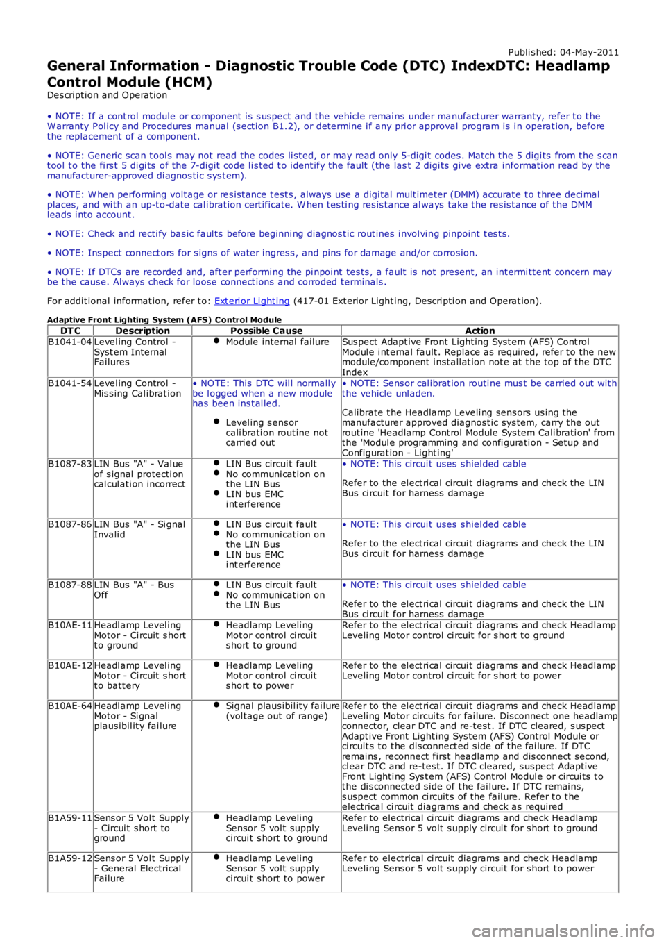
General Information - Diagnostic Trouble Code (DTC) IndexDTC: Headlamp
Control Module (HCM)
Des cript ion and Operat ion
• NOTE: If a cont rol module or component i s s uspect and the vehicl e remai ns under manufacturer warrant y, refer t o t heW arranty Pol icy and Procedures manual (s ect ion B1.2), or determine i f any pri or approval program is i n operat ion, beforet he replacement of a component.
• NOTE: Generic scan t ool s may not read the codes li st ed, or may read only 5-digi t codes . Match t he 5 digi ts from t he s cant ool t o t he fi rs t 5 di gi ts of the 7-digit code li s ted t o i dent ify the fault (the last 2 digi ts gi ve ext ra informati on read by themanufacturer-approved di agnos ti c s ys t em).
• NOTE: W hen performing volt age or res is t ance t est s , always use a digi tal mult imeter (DMM) accurat e t o t hree deci malplaces, and wi th an up-t o-date cal ibrat ion cert ificate. W hen tes ti ng res is t ance al ways take t he res is t ance of t he DMMleads i nt o account .
• NOTE: Check and recti fy bas ic faul ts before beginni ng diagnos t ic rout ines i nvol vi ng pinpoint t es t s.
• NOTE: Ins pect connect ors for s igns of water ingres s , and pins for damage and/or corros ion.
• NOTE: If DTCs are recorded and, aft er performi ng the pi npoi nt tes ts , a fault is not present , an int ermi tt ent concern maybe t he caus e. Always check for loose connect ions and corroded terminals .
For addit ional informat ion, refer t o: Ext eri or Li ght ing (417-01 Ext erior Light ing, Descri pti on and Operat ion).
Adaptive Front Lighting System (AFS) C ontrol Module
DT CDescriptionPossible CauseActionB1041-04Level ing Control -Syst em InternalFailures
Module internal failureSus pect Adapt ive Front Light ing Syst em (AFS) Cont rolModul e i nt ernal fault . Replace as required, refer t o t he newmodule/component i nst all at ion not e at t he top of t he DTCIndexB1041-54Level ing Control -Mis s ing Cal ibrat ion• NO TE: This DTC wil l normall ybe l ogged when a new modulehas been ins t al led.
Level ing s ens orcali brati on rout ine notcarried out
• NOTE: Sens or cal ibrat ion routi ne mus t be carried out wit hthe vehicle unl aden.
Calibrate t he Headlamp Leveli ng sens ors us ing themanufacturer approved diagnost ic sys tem, carry t he outrout ine 'Headlamp Cont rol Module Sys tem Cali brati on' fromthe 'Modul e programming and confi gurati on - Setup andConfigurat ion - Li ght ing'B1087-83LIN Bus "A" - Val ueof s ignal protecti oncal cul ati on incorrect
LIN Bus circui t faultNo communi cat ion ont he LIN BusLIN bus EMCi nt erference
• NOTE: This circui t uses s hiel ded cable
Refer to the el ect ri cal circui t diagrams and check the LINBus ci rcuit for harness damage
B1087-86LIN Bus "A" - Si gnalInvali dLIN Bus circui t faultNo communi cat ion ont he LIN BusLIN bus EMCi nt erference
• NOTE: This circui t uses s hiel ded cable
Refer to the el ect ri cal circui t diagrams and check the LINBus ci rcuit for harness damage
B1087-88LIN Bus "A" - BusOffLIN Bus circui t faultNo communi cat ion ont he LIN Bus
• NOTE: This circui t uses s hiel ded cable
Refer to the el ect ri cal circui t diagrams and check the LINBus ci rcuit for harness damageB10AE-11Headl amp Level ingMotor - Ci rcuit s hortt o ground
Headlamp Leveli ngMot or control ci rcuits hort t o ground
Refer to the el ect ri cal circui t diagrams and check Headl ampLeveli ng Motor control ci rcuit for s hort t o ground
B10AE-12Headl amp Level ingMotor - Ci rcuit s hortt o batt ery
Headlamp Leveli ngMot or control ci rcuits hort t o power
Refer to the el ect ri cal circui t diagrams and check Headl ampLeveli ng Motor control ci rcuit for s hort t o power
B10AE-64Headl amp Level ingMotor - Si gnalplaus ibil it y fai lure
Signal plaus ibil it y fai lure(vol tage out of range)Refer to the el ect ri cal circui t diagrams and check Headl ampLeveli ng Motor circui ts for fai lure. Di sconnect one headlampconnect or, clear DTC and re-t est . If DTC cleared, s us pectAdapt ive Front Light ing Sys tem (AFS) Control Module orci rcuit s t o t he dis connect ed s ide of t he fai lure. If DTCremai ns , reconnect first headlamp and dis connect s econd,cl ear DTC and re-tes t. If DTC cleared, s us pect Adapt iveFront Lighti ng Sys t em (AFS) Cont rol Modul e or circui ts t othe di s connect ed s ide of t he fai lure. If DTC remai ns,s us pect common ci rcuit s of the fail ure. Refer t o t heelectrical ci rcuit diagrams and check as requi red
B1A59-11Sens or 5 Vol t Supply- Circui t s hort toground
Headlamp Leveli ngSensor 5 vol t supplycircui t s hort to ground
Refer to electrical ci rcuit diagrams and check HeadlampLeveli ng Sens or 5 volt s upply circui t for s hort t o ground
B1A59-12Sens or 5 Vol t Supply- General ElectricalFailure
Headlamp Leveli ngSensor 5 vol t supplycircui t s hort to power
Refer to electrical ci rcuit diagrams and check HeadlampLeveli ng Sens or 5 volt s upply circui t for s hort t o power
Page 101 of 3229
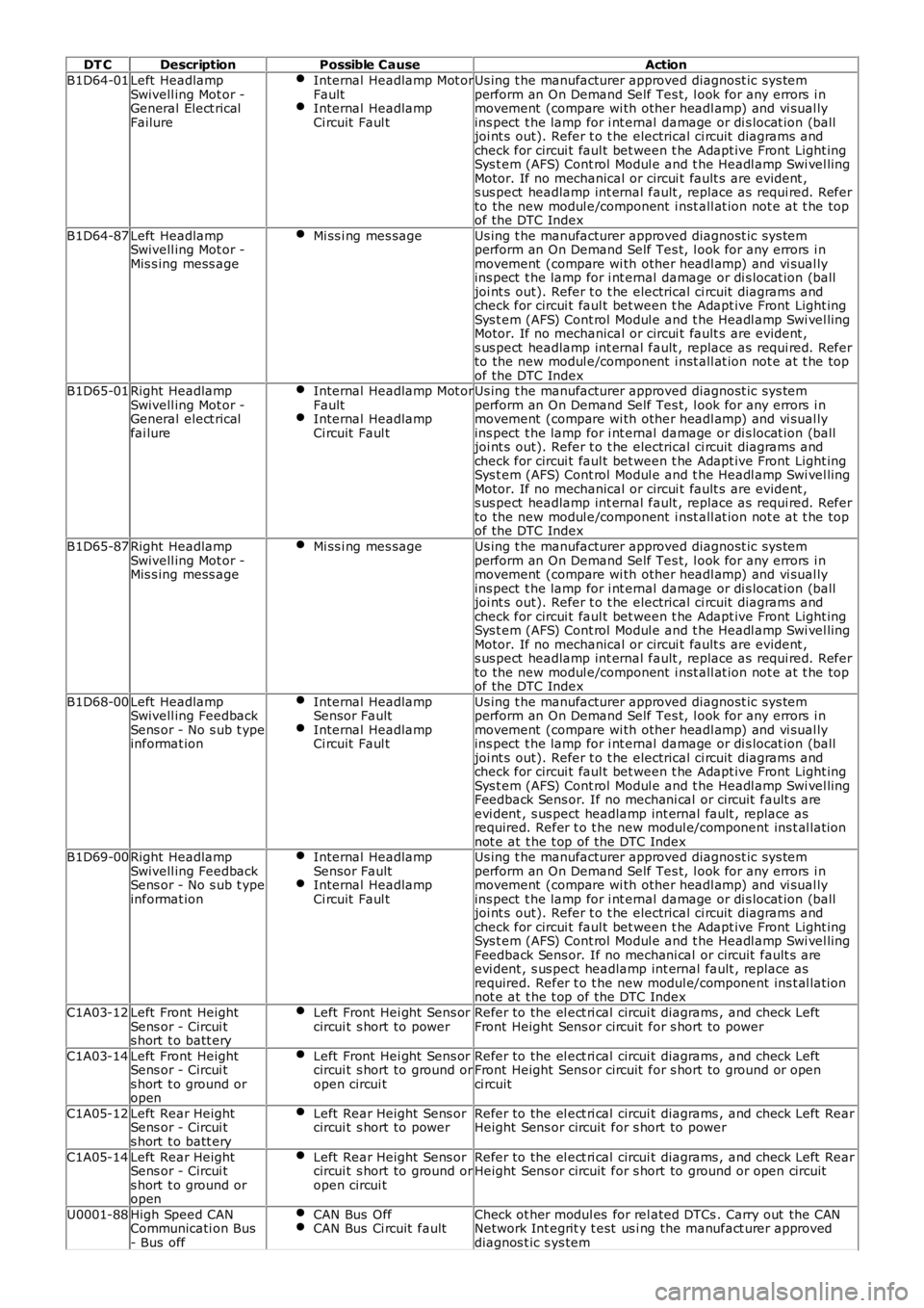
DT CDescriptionPossible CauseAction
B1D64-01Left HeadlampSwivell ing Mot or -General Elect ricalFailure
Internal Headlamp Mot orFaultInternal HeadlampCi rcuit Faul t
Us ing t he manufacturer approved diagnost ic sys temperform an On Demand Self Tes t, l ook for any errors i nmovement (compare wi th other headl amp) and vi sual lyins pect t he lamp for i nt ernal damage or di s locat ion (balljoi nt s out). Refer t o t he electrical ci rcuit diagrams andcheck for circui t faul t bet ween t he Adapt ive Front Light ingSys t em (AFS) Cont rol Modul e and t he Headl amp Swi vel lingMotor. If no mechanical or circui t fault s are evident ,s us pect headlamp int ernal fault , replace as requi red. Referto the new modul e/component i nst all at ion not e at t he topof the DTC Index
B1D64-87Left HeadlampSwivell ing Mot or -Mis s ing mess age
Mi ss i ng mes sageUs ing t he manufacturer approved diagnost ic sys temperform an On Demand Self Tes t, l ook for any errors i nmovement (compare wi th other headl amp) and vi sual lyins pect t he lamp for i nt ernal damage or di s locat ion (balljoi nt s out). Refer t o t he electrical ci rcuit diagrams andcheck for circui t faul t bet ween t he Adapt ive Front Light ingSys t em (AFS) Cont rol Modul e and t he Headl amp Swi vel lingMotor. If no mechanical or circui t fault s are evident ,s us pect headlamp int ernal fault , replace as requi red. Referto the new modul e/component i nst all at ion not e at t he topof the DTC IndexB1D65-01Right HeadlampSwivell ing Mot or -General elect ricalfai lure
Internal Headlamp Mot orFaultInternal HeadlampCi rcuit Faul t
Us ing t he manufacturer approved diagnost ic sys temperform an On Demand Self Tes t, l ook for any errors i nmovement (compare wi th other headl amp) and vi sual lyins pect t he lamp for i nt ernal damage or di s locat ion (balljoi nt s out). Refer t o t he electrical ci rcuit diagrams andcheck for circui t faul t bet ween t he Adapt ive Front Light ingSys t em (AFS) Cont rol Modul e and t he Headl amp Swi vel lingMotor. If no mechanical or circui t fault s are evident ,s us pect headlamp int ernal fault , replace as requi red. Referto the new modul e/component i nst all at ion not e at t he topof the DTC Index
B1D65-87Right HeadlampSwivell ing Mot or -Mis s ing mess age
Mi ss i ng mes sageUs ing t he manufacturer approved diagnost ic sys temperform an On Demand Self Tes t, l ook for any errors i nmovement (compare wi th other headl amp) and vi sual lyins pect t he lamp for i nt ernal damage or di s locat ion (balljoi nt s out). Refer t o t he electrical ci rcuit diagrams andcheck for circui t faul t bet ween t he Adapt ive Front Light ingSys t em (AFS) Cont rol Modul e and t he Headl amp Swi vel lingMotor. If no mechanical or circui t fault s are evident ,s us pect headlamp int ernal fault , replace as requi red. Referto the new modul e/component i nst all at ion not e at t he topof the DTC Index
B1D68-00Left HeadlampSwivell ing FeedbackSens or - No s ub t ypeinformat ion
Internal HeadlampSensor FaultInternal HeadlampCi rcuit Faul t
Us ing t he manufacturer approved diagnost ic sys temperform an On Demand Self Tes t, l ook for any errors i nmovement (compare wi th other headl amp) and vi sual lyins pect t he lamp for i nt ernal damage or di s locat ion (balljoi nt s out). Refer t o t he electrical ci rcuit diagrams andcheck for circui t faul t bet ween t he Adapt ive Front Light ingSys t em (AFS) Cont rol Modul e and t he Headl amp Swi vel lingFeedback Sens or. If no mechani cal or circuit fault s areevi dent , s us pect headlamp int ernal fault , replace asrequired. Refer t o t he new modul e/component ins t al lat ionnot e at t he t op of the DTC IndexB1D69-00Right HeadlampSwivell ing FeedbackSens or - No s ub t ypeinformat ion
Internal HeadlampSensor FaultInternal HeadlampCi rcuit Faul t
Us ing t he manufacturer approved diagnost ic sys temperform an On Demand Self Tes t, l ook for any errors i nmovement (compare wi th other headl amp) and vi sual lyins pect t he lamp for i nt ernal damage or di s locat ion (balljoi nt s out). Refer t o t he electrical ci rcuit diagrams andcheck for circui t faul t bet ween t he Adapt ive Front Light ingSys t em (AFS) Cont rol Modul e and t he Headl amp Swi vel lingFeedback Sens or. If no mechani cal or circuit fault s areevi dent , s us pect headlamp int ernal fault , replace asrequired. Refer t o t he new modul e/component ins t al lat ionnot e at t he t op of the DTC Index
C1A03-12Left Front HeightSens or - Circui ts hort t o batt ery
Left Front Hei ght Sens orcircui t s hort to powerRefer to the el ect ri cal circui t diagrams , and check LeftFront Height Sens or circuit for s hort to power
C1A03-14Left Front HeightSens or - Circui ts hort t o ground oropen
Left Front Hei ght Sens orcircui t s hort to ground oropen circui t
Refer to the el ect ri cal circui t diagrams , and check LeftFront Height Sens or circuit for s hort to ground or openci rcuit
C1A05-12Left Rear HeightSens or - Circui ts hort t o batt ery
Left Rear Height Sens orcircui t s hort to powerRefer to the el ect ri cal circui t diagrams , and check Left RearHeight Sens or circuit for s hort to power
C1A05-14Left Rear HeightSens or - Circui ts hort t o ground oropen
Left Rear Height Sens orcircui t s hort to ground oropen circui t
Refer to the el ect ri cal circui t diagrams , and check Left RearHeight Sens or circuit for s hort to ground or open ci rcuit
U0001-88High Speed CANCommunicati on Bus- Bus off
CAN Bus OffCAN Bus Ci rcuit faultCheck ot her modul es for rel ated DTCs . Carry out the CANNetwork Int egrit y t est us i ng the manufact urer approveddiagnos t ic s ys tem
Page 175 of 3229
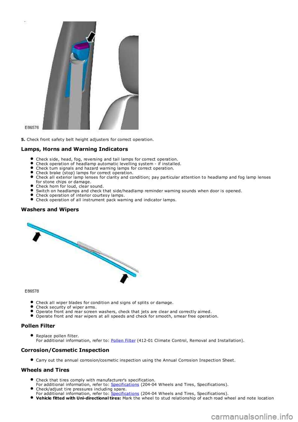
5. Check front s afet y belt height adjus ters for correct operat ion.
Lamps, Horns and Warning Indicators
Check s i de, head, fog, revers ing and tail l amps for correct operat ion.Check operat ion of headlamp aut omati c levelli ng s yst em - if ins t al led.Check t urn si gnal s and hazard warni ng lamps for correct operati on.Check brake (s t op) l amps for correct operat ion.Check al l ext eri or l amp l ens es for cl arit y and condi ti on; pay parti cular at tent ion to headl amp and fog lamp lens esfor s t one chi ps or damage.Check horn for l oud, clear s ound.Swit ch on headl amps and check t hat si de/headl amp reminder warning s ounds when door is opened.Check operat ion of i nteri or courtes y lamps .Check operat ion of al l i nst rument pack warni ng and indicator l amps.
Washers and Wipers
Check al l wiper blades for condi ti on and s igns of s pl it s or damage.Check s ecurit y of wi per arms .Operat e front and rear s creen washers, check that jet s are cl ear and correctl y aimed.Operat e front and rear wipers at all s peeds and check for s moot h, s mear free operation.
Pollen Filter
Replace pol len fil ter.For addit ional informat ion, refer t o: Pollen Fi lt er (412-01 Cl imat e Control, Removal and Ins tall ati on).
Corrosion/Cosmetic Inspection
Carry out the annual corros ion/cos meti c ins pect ion us ing t he Annual Corros ion Inspecti on Sheet .
Wheels and Tires
Check t hat ti res comply wit h manufacturer's specificati on.For addit ional informat ion, refer t o: Specificati ons (204-04 W heels and Tires , Specificati ons ).Check/adjust t ire pres s ures i ncl udi ng s pare.For addit ional informat ion, refer t o: Specificati ons (204-04 W heels and Tires , Specificati ons ).Vehicle fitted with Uni-directional tires: Mark t he wheel to st ud rel ati ons hip of each road wheel and note locat ion