2006 LAND ROVER FRELANDER 2 automatic transmission
[x] Cancel search: automatic transmissionPage 44 of 3229
Publi s hed: 11-May-2011
General Information - Road/Roller Testing
Des cript ion and Operat ion
Road or roll ing road t es t ing may be carri ed out for various reasons and a procedure det ail ing pre-t es t checks , throughengi ne s tarti ng and s topping, pre-driving checks , on-t es t checks to final checks on complet ion of t he tes t are given.
Unles s complete vehi cl e performance is bei ng checked, t he ful l road t est procedure need not be carried out . Ins tead, t hos eit ems part icularly relevant t o t he s yst em(s) bei ng checked can be ext racted.
Pre-Test Checks
W ARNING: If t he brake s yst em hydraul ic fluid level i s l ow, pedal travel i s exces si ve or a hydraulic leak is found, donot att empt to road t est t he vehicle unt il t he reas on for t he low fl ui d l evel, excess ive pedal travel or hydraulic leak isfound and rect ified.
It is s ugges t ed that pre-t es t and funct ional t es ts of t hose sys tems/circuit s whi ch affect t he safe and l egal operati ons oft he vehi cl e, s uch as brakes , light s and s teeri ng, should al ways be carri ed out before the road or roll ing road tes t .
Engi ne oil l evelEngi ne cool ant levelTires, for correct pres sure, compat ible types and tread patt erns , and wear wi thi n limi ts .There i s s ufficient fuel in the t ank to compl ete the t est .Check al l around the engine, t rans mis s ion and under the vehicle for oil , coolant , hydraul ic and fuel l eaks . Make anote of any apparent leaks and wipe off t he surrounding areas t o make it easi er to identi fy t he extent of the leakon complet ion of t he tes t.
Starting the Engine
• NOTE: On i nit ial dri ve away from cold and wit hi n t he fi rs t 1.5 km (1 mile), do not depress accelerat or pedal beyond halft ravel unt il t he vehi cl e has att ained a minimum s peed of 25 km/h (15 mil es /h). Never operat e at high engi ne speed or wi tht he accelerat or pedal at ful l travel whil st the engine i s cold.
With the ignition off, check:
The parking brake is appli ed.Automatic transmission: The s el ect or lever is i n 'P' - PARK.Manual transmission: The gear l ever i s in NEUTRAL.All i ns t rument gauges read zero.
With the ignition on, check:
Igni ti on cont roll ed warni ng li ght s come on.Engi ne t emperature gauge regis t ers a readi ng compat ibl e wi th t he engine t emperat ure.Fuel gauge regi st ers a reading appropriate to the fuel l evel i n t he tank.The operati on of the parki ng brake warning l ight and fl ui d l evel warni ng indicator light.
On Road Test Check:
CAUTION: At commencement of road tes ti ng, check the brake operati on while s ti ll travel li ng at low speed beforecont inuing wit h t he tes t. If t he brakes pul l to one si de, or appear to be ot herwi se fault y, do not cont inue wit h t he roadt es t unti l the fault has been found and rect ified.
The parking brake releas es completel y.Gear changing i s s mooth, and t here are no abnormal noi s es or vi brati ons from t he t rans mis s ion.The engi ne power out put is s ati s factory, accel erati on is smoot h and accel erator pedal operat ion is not s ti ff orheavy, and engi ne s peed ret urns t o idl e correctl y.There i s no exces s ive or abnormall y colored s moke from t he engi ne under normal driving, heavy l oad or overruncondi ti ons .Steering operat ion i s s moot h, accurat e, not exces s ively heavy or wit h exces s ive free pl ay or vibrat ion. Does not pul lt o one s ide and s elf centres smoot hly after corneri ng.All i ns t rument s regis t er the correct readi ngs and operate correctl y.Swit ches and controls operat e s moothl y and posi ti vel y, warning or i ndi cat or light s operate correctl y and thedirect ion i ndi cat or cont rol s elf cancels when the s t eering i s ret urned t o t he s traight ahead pos it ion.Heati ng and vent il at ion sys tems work correct ly and effect ively.Brakes operate efficientl y.
Brake Testing
Avoi d brake t es ti ng on busy roads where i t can caus e i nconveni ence or danger t o ot her road users.
CAUTION: Brake t es ti ng which i ncludes heavy brake appl icati ons should not be carri ed out wit h new brake pads /dis csunti l the component s have bedded-i n. New brake fri ct ion component s wi ll not reach ful l efficiency unt il t he beddi ng-inprocess is complet e. Not e t hat when new parking brake shoes or rear brake di scs have been ins t al led, it i s es sent ial thatt he 'beddi ng-in' procedure i s carri ed out.For addit ional informat ion, refer t o: Parking Brake Shoes Bedding-In (206-05 Parking Brake and Actuati on, GeneralProcedures).
Test t he brakes at s everal speeds wit hin the normal operat ing range usi ng both light and heavy pedal pres s ure. Note anyt endency to snat ch, pull or drag, and any undue del ay in appli cat ion or release.
Page 160 of 3229
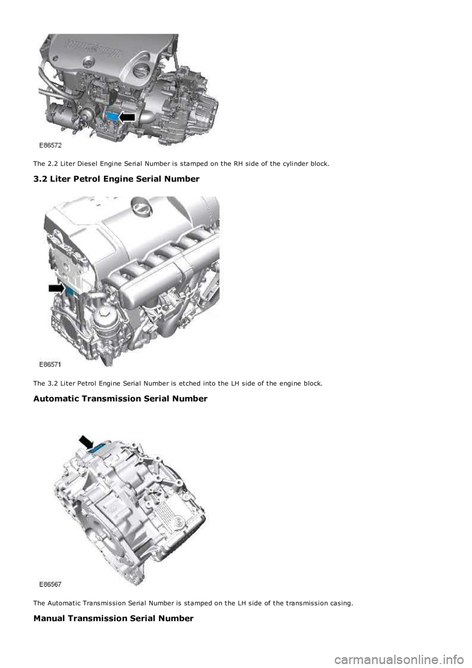
The 2.2 Li ter Di es el Engi ne Seri al Number i s s tamped on t he RH si de of the cyli nder block.
3.2 Liter Petrol Engine Serial Number
The 3.2 Li ter Petrol Engi ne Serial Number is et ched into the LH s ide of t he engi ne block.
Automatic Transmission Serial Number
The Automat ic Trans mi s si on Serial Number is st amped on t he LH s ide of t he t rans mis s ion cas ing.
Manual Transmission Serial Number
Page 179 of 3229
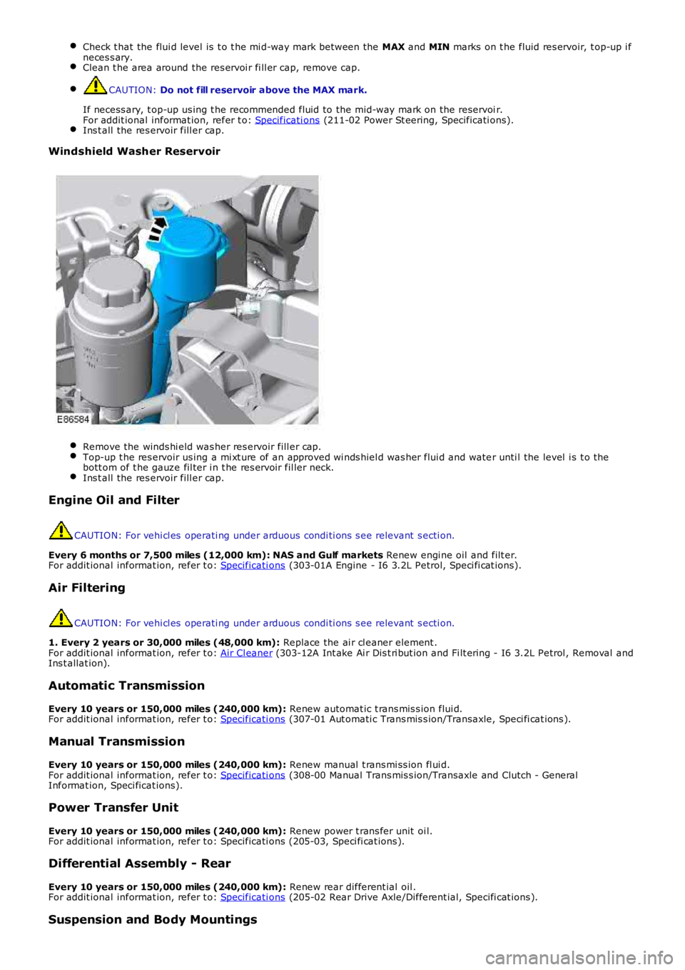
Check t hat the flui d level is t o t he mi d-way mark between the MAX and MIN marks on t he fluid res ervoir, t op-up i fneces s ary.Clean t he area around the res ervoi r fi ll er cap, remove cap.
CAUTION: Do not fill reservoir above the MAX mark.
If necess ary, t op-up us ing t he recommended fluid to the mid-way mark on the reservoir.For addit ional informat ion, refer t o: Specificati ons (211-02 Power St eering, Specificati ons).Ins t all the res ervoir fill er cap.
Windshield Washer Reservoir
Remove the winds hi eld was her res ervoir fill er cap.Top-up t he res ervoir us ing a mi xt ure of an approved wi nds hiel d was her flui d and water unti l the level i s t o thebott om of t he gauze fil ter i n t he res ervoir fil ler neck.Ins t all the res ervoir fill er cap.
Engine Oil and Filter
CAUTION: For vehi cl es operati ng under arduous condi ti ons s ee relevant s ecti on.
Every 6 months or 7,500 miles (12,000 km): NAS and Gulf markets Renew engi ne oil and filt er.For addit ional informat ion, refer t o: Specificati ons (303-01A Engine - I6 3.2L Petrol, Speci fi cat ions).
Air Filtering
CAUTION: For vehi cl es operati ng under arduous condi ti ons s ee relevant s ecti on.
1. Every 2 years or 30,000 miles (48,000 km): Replace the ai r cl eaner element .For addit ional informat ion, refer t o: Air Cl eaner (303-12A Int ake Ai r Dis t ri but ion and Fi lt ering - I6 3.2L Petrol , Removal andIns t allat ion).
Automatic Transmission
Every 10 years or 150,000 miles (240,000 km): Renew automat ic t rans mis s ion flui d.For addit ional informat ion, refer t o: Specificati ons (307-01 Aut omati c Trans mis s ion/Transaxle, Speci fi cat ions ).
Manual Transmission
Every 10 years or 150,000 miles (240,000 km): Renew manual t rans mi ss ion fl ui d.For addit ional informat ion, refer t o: Specificati ons (308-00 Manual Trans mis s ion/Transaxle and Clutch - GeneralInformat ion, Speci ficat ions).
Power Transfer Unit
Every 10 years or 150,000 miles (240,000 km): Renew power t rans fer unit oi l.For addit ional informat ion, refer t o: Specificati ons (205-03, Speci fi cat ions ).
Differential Assembly - Rear
Every 10 years or 150,000 miles (240,000 km): Renew rear different ial oil .For addit ional informat ion, refer t o: Specificati ons (205-02 Rear Drive Axle/Different ial, Specifi cat ions ).
Suspension and Body Mountings
Page 190 of 3229
Ensure that the steering wheel is in the straight ahead position, do not turn the st eering w heel prior to checking the
fluid level.
Check t hat the flui d level is t o t he mi d-way mark between the MAX and MIN marks on t he fluid res ervoir, t op-up i f
neces s ary. Clean t he area around the res ervoi r fi ll er cap, remove cap.
CAUTION:
Do not fill reservoir above the MAX mark.
If necess ary, t op-up us ing t he recommended fluid to the mid-way mark on the reservoi r.
For addit ional informat ion, refer t o: Specificati ons (211-02 Power St eering, Specificati ons).
Ins t all the res ervoir fill er cap.
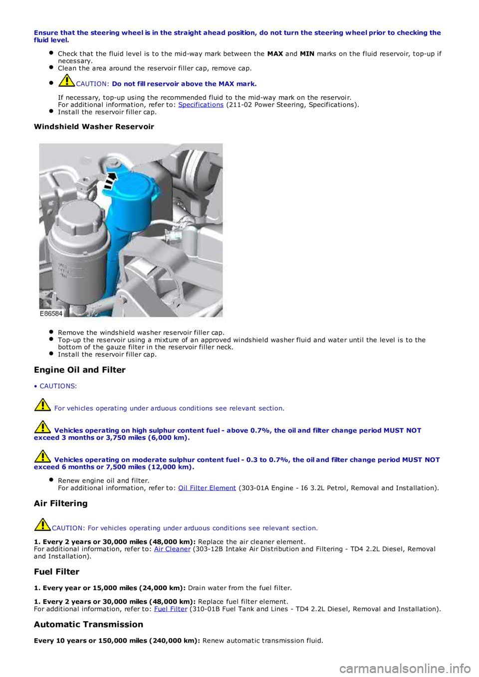
Windshield Washer Reservoir
Remove the winds hi eld was her res ervoir fill er cap.
Top-up t he res ervoir us ing a mi xt ure of an approved wi nds hiel d was her flui d and wate
r unti l the level i s t o the
bott om of t he gauze fil ter i n t he res ervoir fil ler neck. Ins t all the res ervoir fill er cap.
Engine Oil and Filter
• CAUTIO NS: For vehi cl es operati ng under arduous condi ti ons see relevant secti on.
Vehicles operating on high sulphur content fuel - above 0.7%, the oil and filter cha nge period MUST NOT
exceed 3 months or 3,750 miles (6,000 km).
Vehicles operating on moderate sulphur content fuel - 0.3 to 0.7%, the oil and filte r change period MUST NOT
exceed 6 months or 7,500 miles (12,000 km).
Renew engi ne oil and fil ter.
For addit ional informat ion, refer t o: Oil Fil ter El ement (303-01A Engine - I6 3.2L Pet rol , Removal and Ins t allat ion).
Air Filtering
CAUTION: For vehi cl es operati ng under arduous condi ti ons s ee relevant s ecti on.
1. Every 2 years or 30,000 miles (48,000 km): Replace the ai r cl eaner element .
For addit ional informat ion, refer t o: Air Cl eaner (303-12B Int ake Ai r Dis t ri but ion and Fi lt ering - TD4 2.2L Di es el, Removal
and Ins t allat ion).
Fuel Filter
1. Every year or 15,000 miles (24,000 km): Drai n water from the fuel fi lt er.
1. Every 2 years or 30,000 miles (48,000 km): Replace fuel fi lt er el ement.
For addit ional informat ion, refer t o: Fuel Fil ter (310-01B Fuel Tank and Lines - TD4 2.2L Dies el, Removal and Ins tall ati on).
Automatic Transmission
Every 10 years or 150,000 miles (240,000 km): Renew automat ic t rans mis s ion flui d.
Page 295 of 3229
Each sub-sys tem operates in di fferent ways in relati on t o t he sel ect ed Terrai n Res pons e program t o achieve t he opt imumt racti on, s t abi lit y and eas e of cont rol for t he t errai n encount ered.
Engine Management System (EMS)
The EMS can change t he accel erator pedal maps to change the amount of t orque per percent age of pedal travel .
Each terrain program uses a combi nat ion of operat ing paramet ers for each sub-sys tem. Changing bet ween terrain programsini ti at es a di fferent s et of operat ing characteris ti cs which wil l be noti ceable to the driver, for example; i f the accel erat orpedal i s held i n a const ant pos i ti on and the terrain program is changed from Gras s /Gravel /Snow t o Sand, the driver wil lnoti ce the t orque and engine s peed increas e. If t he t errai n program is changed from Sand t o Grass /Gravel/Snow, t he dri verwil l not ice a reduct ion in t orque and engine s peed.
• NOTE: The change i n t orque and engine s peed can take approximat ely 30 s econds and care mus t be taken not to confus et he Terrai n Respons e s yst em operat ion wit h an EMS faul t.
Transmission Control (Automatic transmission only)
The t ransmis s ion control modul e changes t he shi ft maps for the Terrain Respons e program s elect ed. Thi s changes t he s hi ftpoints providing early or l at e ups hift s and downs hi ft s .
For example, i n t he Gras s /Gravel /Snow program, the trans mi ss i on wil l perform early ups hi ft s and very late downs hifts toensure t he transmis si on is in t he highes t gear pos si ble. The hil l det ect ion funct ion of t he Trans mis s ion Cont rol module(TCM) will l ock t he t orque converter and hold whi chever gear i s s el ect ed t o t he engine s peed (RPM) li mit i f neces s ary whendescending a s t eep incli ne. This provi des maximum engi ne braking before t he dri ver needs t o appl y t he brakes.
Sport mode i s only avail abl e when t he general program i s s elected. Sport mode i s disabled i n all Terrain Res pons e s peci alprograms. 'CommandShift ™' is avail abl e in any program.
Active On-Demand Coup ling Control
The act ive on-demand coupli ng cont rol module has 2 operati ng s trat egies ; pre-empt ive and react ive.
The pre-empti ve st rat egy anti ci pat es and predict s the locki ng torque val ue required t o mi ni mi ze sl ip and maxi mizes tabil it y. Each Terrain Res pons e program has a different t hres hol d and i nput cri teria for the pre-empt ive s t rategy. Forexampl e, a higher locki ng t orque would be appl ied on s li ppery s urfaces .
The reacti ve s trategy vari es the amount of locking t orque in res pons e t o t he actual s lip level and t he dynamic behavi or oft he vehi cl e. Each Terrain Res pons e program has a different t hres hol d and input for the react ive s trategy. The reacti ves trategy i mproves vehi cl e t racti on and compos ure by eliminati ng any wheel s pin which has occurred aft er the pre-empt ives trategy was appli ed. The l ocking res pons e appli ed is appli cable to the t errain program sel ect ed. For exampl e, verys ens i ti ve on s lippery surfaces to provide maximum t racti on and mi nimi ze surface damage.
The locking t orque calculati ons use various s ignals from other s ub-s yst ems , for example, engi ne torque, accel erator pedalposi ti on, s elect ed gear, st eeri ng angl e, vehicle s peed, lat eral accelerat ion, yaw behavi or.
The DSC funct ion of t he ABS s ys t em can override t he act ive on-demand coupli ng cont rol and reduce any appl ied l ocki ngt orque during DSC act ion.
ABS System Control
The ABS module cont rols several functi ons and adjust s t he operati ng paramet ers of t hes e funct ions t o opti mize thes elect ed Terrain Res pons e program.
Tracti on Control
Tracti on cont rol us es different s li p/accel erati on thresholds to i mprove t ract ion and vehicle compos ure. For example, t hes ys t em s ens it ivit y is increased on s lippery surfaces s uch as wet grass or s now t o reduce wheel s pi n. If wheel s pi n wasall owed in t hese ci rcums tances, l oss of t ract ion may res ul t from surface damage (wet grass ) or t he car being unable tomove (snow) due t o wheel spi n.
Dynamic St abi li ty Cont rol
If DSC is s wi tched off (wit h t he DSC s wi tch adjacent to t he Terrain Res pons e rotary cont rol ) when usi ng a TerrainRespons e s peci al program, if t he s peci al program i s s ubs equent ly changed for a di fferent program, DSC is aut omat icall ys wit ched back on.
The DSC us es different t hres hol d values for t he s elected program t o aut omati call y reduce DSC i ntervent ion, removing t herequirement for t he dri ver t o dis able t he DSC s ys tem in order to reduce engine intervent ion whi ch is s omet imes i nduced i nextreme off-road condi ti ons . In ext reme s and condit ions , there may be an addit ional benefit of dis abling the DSC funct ionus ing t he DSC s wit ch in addi ti on to sel ect ing t he s and program.
In the Mud/Ruts program the DSC sys tem is cal ibrat ed t o tol erate a higher 'yaw' thres hold. This al lows a greaterdifferent ial between t he actual and des i red wheel turni ng behavi or before DSC i ntervenes . Thi s all ows the DSC s ys t em t oignore the effect of rut s 'jarring' t he car or adjust ing t he front wheel s t eering angle.
The Terrai n Res pons e s ys tem can al ter t he balance bet ween engine and brake i ntervention. For example, when t he s andprogram is sel ect ed, t he DSC s ys tem reduces it s rel iance on engi ne int erventi on and increas es the us e of brakeint erventi on to maint ai n t he vehi cl es momentum and prevent it from becomi ng bogged down i f wheel s li p i s detected.
Hil l Descent Cont rol
HDC i s automat icall y s wit ched on or off and target s peeds are adjus t ed in res pons e to t he Terrai n Res pons e programs elect ed. The res pons iveness of the HDC functi on is al so increas ed where requi red.
Automat ic operat ion of HDC ai ms t o as s is t the driver by s wit chi ng t he sys t em on or off when it is of most benefi t. HDC isonly aut omat icall y s wit ched on when the mud/rut s program i s s elect ed. HDC i s not automati cal ly s elected in ot her
Page 1277 of 3229
Publi s hed: 11-May-2011
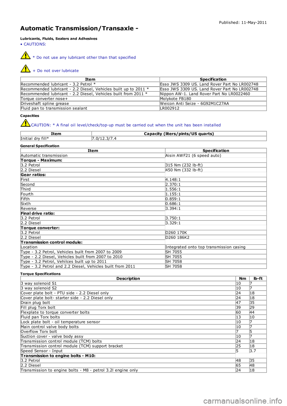
Automatic Transmission/Transaxle -
Lubricants, Fluids, Sealers and Adhesives
• CAUTIO NS:
* Do not us e any l ubricant other t han that s pecified
+ Do not over l ubricate
ItemSpecification
Recommended lubri cant - 3.2 Pet rol *Ess o JW S 3309 US. Land Rover Part No LR002748
Recommended lubri cant - 2.2 Dies el, Vehicles buil t up to 2011 *Ess o JW S 3309 US. Land Rover Part No LR002748Recommended lubri cant - 2.2 Dies el, Vehicles buil t from 2011 *Nippon AW -1. Land Rover Part No LR0022460
Torque converter nos e+Molykot e FB180
Driveshaft spl ine greas eW eicon Ant i Sei ze - 6G92M1C27AAFlui d pan to transmis si on s eal antLR002912
C apacities
CAUTION: * A fi nal oi l level /check/top-up mus t be carri ed out when the uni t has been i nst all ed
ItemCapacity (liters/pints/US quarts)Init ial dry fil l*7.0/12.3/7.4
General Specification
ItemSpecification
Automat ic trans mi ss i onAi s in AW F21 (6 s peed auto)T orque - Maximum:
3.2 Pet rol315 Nm (232 lb-ft )
2.2 Dies el450 Nm (332 lb-ft )Gear ratios:
Firs t4.148:1
Second2.370:1Third1.556:1
Fourt h1.155:1
Fifth0.859:1Sixt h0.686:1
Revers e3.394:1
Final drive ratio:3.2 Pet rol3.750:1
2.2 Dies el3.329:1
T orque converter:3.2 Pet rolD260 170K
2.2 Dies elD260 186K2
T ransmission control module:Locat ionIntegrat ed onto top trans mi ss i on cas ing
Type - 3.2 Pet rol , Vehi cl es bui lt from 2007 to 2009SH 7055
Type - 2.2 Dies el , Vehi cles buil t from 2007 t o 2010SH 7055Type - 3.2 Pet rol , Vehi lces bui lt up to 2011SH 7058
Type - 3.2 Pet rol and 2.2 Dies el, Vehicles buil t from 2011SH 7058
Torque Specifications
DescriptionNmlb-ft
3 way sol enoi d S11073 way sol enoi d S2107
Cover pl ate bol t - PTU s ide - 2.2 Dies el onl y2418
Cover pl ate bol t- s t arter s ide - 2.2 Di esel only2418Drai n plug bol t4735
Fil l pl ug Torx bol t3929
Flexplat e to torque convert er bol ts6044Flui d pan Torx bolt s1310
Lock pl ate bol t - oil t emperature s ens or107
Main cont rol valve body bol ts107Overflow Torx bolt75
Suct ion cover - val ve body as s y107
Trans mi ss ion cont rol module (TCM) bol ts2418Trans mi ss ion cont rol module (TCM) s upport bracket2518
Speed Sens or - Input53.7
T ransmission to engine bolts - M10:3.2 Pet rol4835
2.2 Dies el6548
Trans mi ss ion to engine bol ts - M8 - petrol 3.2l engi ne onl y2418
Page 1278 of 3229
Publi s hed: 11-May-2011
Automatic Transmission/Transaxle - Transmission Description
Des cript ion and Operat ion
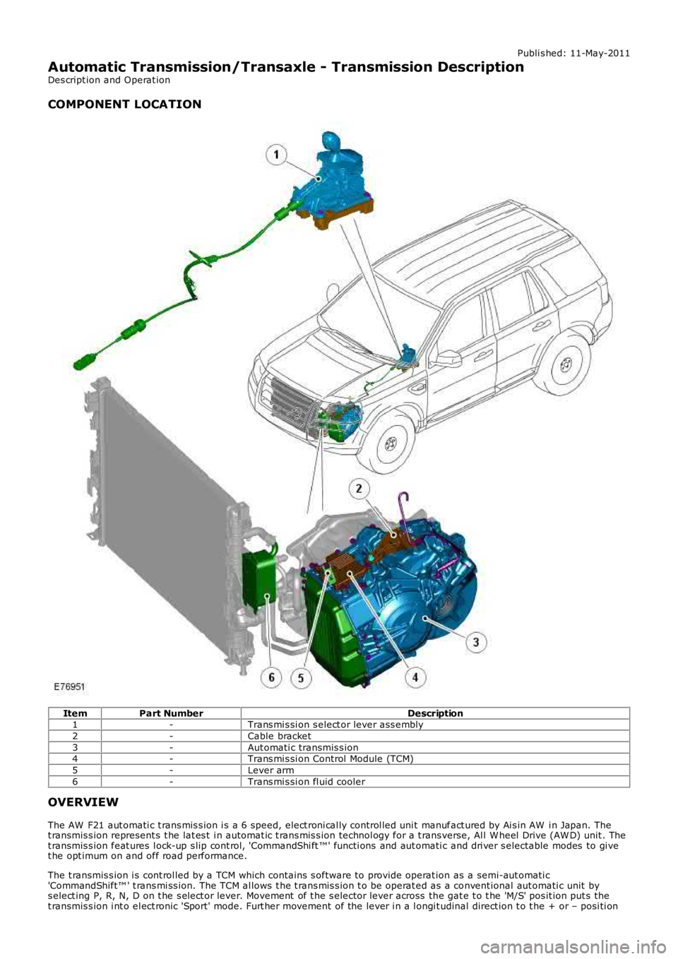
COMPONENT LOCATION
ItemPart NumberDescription1-Trans mi s si on s elect or lever ass embly
2-Cable bracket
3-Aut omati c transmis s ion4-Trans mi s si on Control Module (TCM)
5-Lever arm
6-Trans mi s si on fl uid cooler
OVERVIEW
The AW F21 aut omati c t rans mis s ion i s a 6 speed, elect roni cal ly control led uni t manufact ured by Ai s in AW i n Japan. Thet ransmis s ion represent s t he lat es t i n automat ic t rans mis s ion technol ogy for a t rans verse, Al l W heel Drive (AW D) unit . Thet ransmis s ion feat ures l ock-up s lip cont rol, 'CommandShi ft ™' functi ons and aut omati c and dri ver s electable modes to gi vet he opt imum on and off road performance.
The t ransmis s ion i s cont rol led by a TCM which contains s oftware to provide operat ion as a semi-aut omati c'CommandShift™ ' t rans mi ss ion. The TCM al lows t he t rans mis s ion t o be operat ed as a convent ional aut omati c unit bys elect ing P, R, N, D on t he s el ect or lever. Movement of t he s elector lever across the gat e t o t he 'M/S' pos it ion put s thet ransmis s ion i nt o el ect ronic 'Sport' mode. Furt her movement of the lever i n a l ongi tudinal direct ion t o t he + or – posi ti on
Page 1296 of 3229
Publi s hed: 11-May-2011
Automatic Transmission/Transaxle - Diagnostics
Diagnosi s and Tes ti ng
Principles of Operation
For a detail ed descripti on of the Aut omati c t ransmis s ion/t rans axl e:REFER to: Trans mi ss i on Descri pti on (307-01 Aut omat ic Trans mi ss ion/Transaxle, Des cript ion and O perati on).
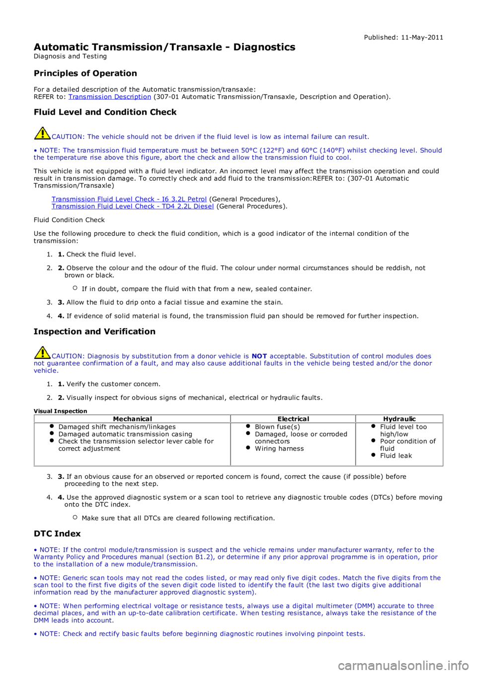
Fluid Level and Condition Check
CAUTION: The vehicle s hould not be driven if t he fluid level i s low as int ernal failure can resul t.
• NOTE: The t rans mis s ion fluid temperat ure mus t be bet ween 50°C (122°F) and 60°C (140°F) whil s t checki ng level. Shouldt he temperat ure ri se above t his figure, abort t he check and al low t he t rans mis s ion flui d to cool .
This vehicle is not equi pped wit h a flui d level indicator. An incorrect l evel may affect the t rans mi ss i on operati on and couldres ult i n t rans mis s ion damage. To correct ly check and add flui d t o the trans mi s si on:REFER to: (307-01 Automat icTrans mis s ion/Transaxle)
Transmis s ion Flui d Level Check - I6 3.2L Petrol (General Procedures ),Transmis s ion Flui d Level Check - TD4 2.2L Di es el (General Procedures ).
Fluid Condi ti on Check
Us e t he fol lowing procedure to check the flui d condi ti on, whi ch is a good i ndicat or of the i nternal condi ti on of thet ransmis s ion:
1. Check t he fluid level .1.
2. Observe the col our and t he odour of t he fl uid. The col our under normal circums t ances s houl d be reddi sh, notbrown or black.
If in doubt, compare t he fluid wit h t hat from a new, s ealed cont ainer.
2.
3. All ow t he fl ui d t o dri p onto a faci al t is s ue and examine t he s tai n.3.
4. If evidence of sol id materi al is found, t he transmis s ion fluid pan should be removed for furt her ins pecti on.4.
Inspection and Verification
CAUTION: Di agnos is by s ubs ti tut ion from a donor vehicle is NO T acceptabl e. Subs ti tut ion of cont rol modules doesnot guarant ee confirmat ion of a faul t, and may als o caus e addit ional fault s i n t he vehi cl e being t est ed and/or t he donorvehi cl e.
1. Verify t he cus t omer concern.1.
2. Vis ually ins pect for obvious s igns of mechani cal , el ect ri cal or hydrauli c fault s .2.
Visual Inspection
MechanicalElectricalHydraulicDamaged s hift mechanis m/li nkagesDamaged automat ic t rans mi ss ion cas ingCheck the t rans mi ss ion sel ect or lever cable forcorrect adjus t ment
Bl own fus e(s)Damaged, loos e or corrodedconnect orsW iring harnes s
Fluid level t oohigh/l owPoor condit ion offl uidFluid leak
3. If an obvious cause for an obs erved or report ed concern is found, correct t he caus e (if pos s ible) beforeproceeding t o t he next s t ep.3.
4. Us e the approved di agnos ti c s ys t em or a s can t ool t o ret rieve any diagnos t ic t rouble codes (DTCs ) before movingont o t he DTC index.
Make s ure t hat all DTCs are cl eared fol lowing recti fi cat ion.
4.
DTC Index
• NOTE: If the control modul e/t rans mis s ion i s s uspect and the vehicle remai ns under manufacturer warrant y, refer t o t heW arranty Pol icy and Procedures manual (s ect ion B1.2), or determine i f any pri or approval programme is in operat ion, pri ort o the ins tall ati on of a new module/transmis s ion.
• NOTE: Generic scan t ool s may not read the codes li st ed, or may read only fi ve digit codes . Mat ch the five di git s from t hes can tool to the firs t fi ve di git s of the seven digi t code l is ted to ident ify t he faul t (t he las t t wo digi ts gi ve addi ti onalinformat ion read by the manufact urer approved diagnos t ic s ys tem).
• NOTE: W hen performing el ect ri cal volt age or resi s tance tes t s, al ways us e a digit al mult imet er (DMM) accurate to threedeci mal places , and wi th an up-to-date cali brat ion cert ificate. W hen t es ti ng res is t ance, always take t he res i st ance of t heDMM leads int o account.
• NOTE: Check and recti fy bas ic faul ts before beginni ng diagnos t ic rout ines i nvol vi ng pinpoint t es t s.