Page 1344 of 3229

Publi s hed: 11-May-2011
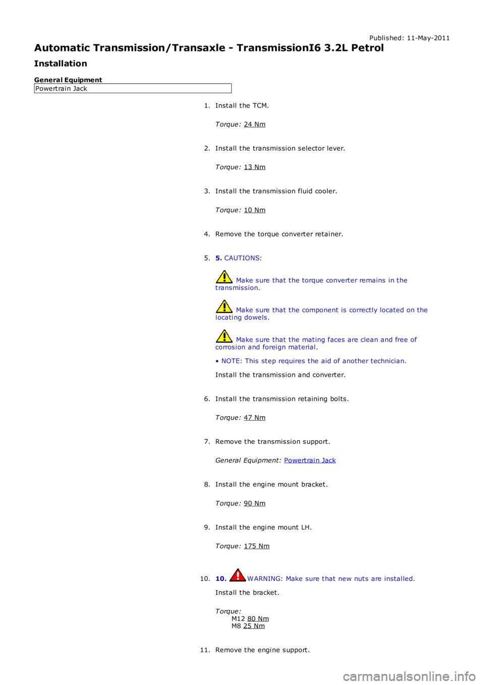
Automatic Transmission/Transaxle - TransmissionI6 3.2L Petrol
Installation
General Equipment Powert rai n Jack
Inst all t he TCM.
T orque: 24 Nm 1.
Inst all t he transmis si on s elector lever.
T orque: 13 Nm 2.
Inst all t he transmis si on fluid cooler.
T orque: 10 Nm 3.
Remove t he torque convert er retai ner.
4.
5. CAUTIONS: Make s ure that t he torque convert er remains in t he
t rans mis s ion. Make s ure that t he component is correctl y located on t he
l ocati ng dowels . Make s ure that t he mat ing faces are clean and free of
corros i on and forei gn mat erial .
• NOTE: This st ep requires t he aid of another t echnician.
Inst all t he transmis si on and convert er.
5.
Inst all t he transmis si on ret aining bol ts .
T orque: 47 Nm 6.
Remove t he transmis si on s upport.
General Equi pment: Powert rai n Jack 7.
Inst all t he engi ne mount bracket .
T orque: 90 Nm 8.
Inst all t he engi ne mount LH.
T orque: 175 Nm 9.
10. W ARNING: Make sure t hat new nut s are ins tal led.
Inst all t he bracket .
T orque: M12 80 Nm M8
25 Nm 10.
Remove t he engi ne s upport .
11.
Page 1347 of 3229

Publi s hed: 11-May-2011
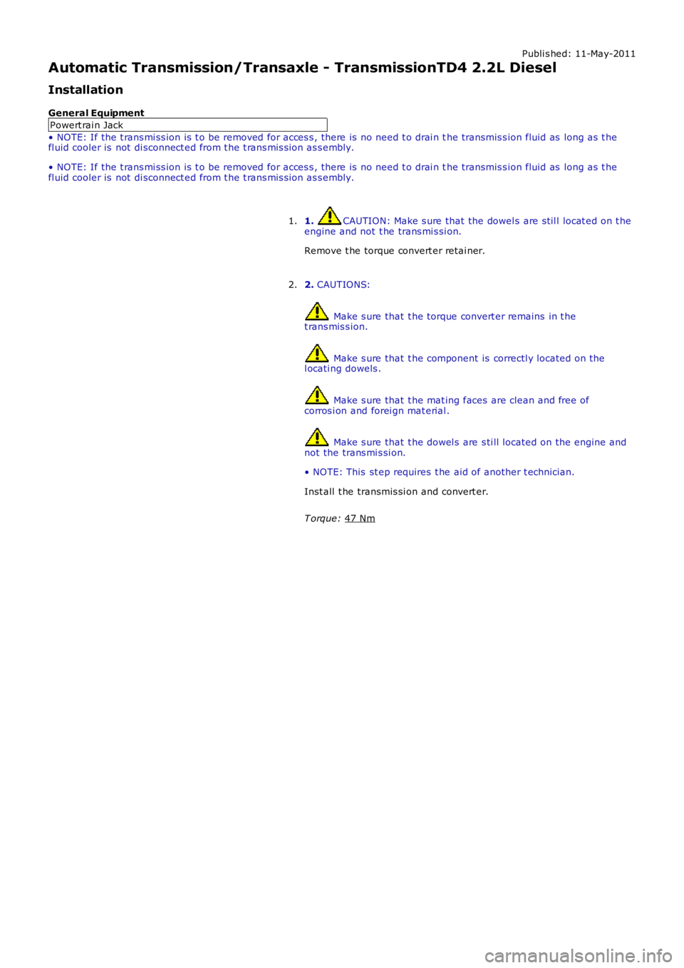
Automatic Transmission/Transaxle - TransmissionTD4 2.2L Diesel
Installation
General Equipment Powert rai n Jack
• NOTE: If the t rans mi ss ion is t o be removed for acces s , there is no need t o drai n t he transmis s ion fluid as long as t he
fl uid cooler is not di sconnect ed from t he t rans mis s ion as s embly.
• NOTE: If the t rans mi ss ion is t o be removed for acces s , there is no need t o drai n t he transmis s ion fluid as long as t he
fl uid cooler is not di sconnect ed from t he t rans mis s ion as s embly.
1. CAUTION: Make s ure that the dowel s are st il l locat ed on t he
engine and not t he trans mi s si on.
Remove t he torque convert er retai ner.
1.
2. CAUTIONS: Make s ure that t he torque convert er remains in t he
t rans mis s ion. Make s ure that t he component is correctl y located on t he
l ocati ng dowels . Make s ure that t he mat ing faces are clean and free of
corros i on and forei gn mat erial . Make s ure that t he dowel s are s ti ll located on the engine and
not the trans mi s si on.
• NOTE: This st ep requires t he aid of another t echnician.
Inst all t he transmis si on and convert er.
T orque: 47 Nm 2.
Page 1368 of 3229
Publi s hed: 11-May-2011
Automatic Transmission/Transaxle External Controls -
General SpecificationItemSpecification
TypeCabl e s hift
Torque Specifications
DescriptionNmlb-ft
Abutment bracket to gearbox bol t2418Shift ass embly to fl oor107
Shift cabl e grommet t o body bolt75
Shift lever to gearbox1410
Page 1369 of 3229
Publi s hed: 11-May-2011
Automatic Transmission/Transaxle External Controls - External Controls
Des cript ion and Operat ion
COMPONENT LOCATION
ItemPart NumberDescription
1-Selector cabl e
2-Selector l ever as sembl y3-Selector knob, gait er and il lumi nat ion modul e
4-Selector l ever mounti ng plat e
OVERVIEW
The automat ic t rans mis s ion ext ernal cont rols compris e a s elect or l ever as s embl y and a t rans mi ss i on cable. The s electorlever allows the driver to sel ect forward or revers e gears and al so to engage s port or manual 'CommandShi ft ™' modes.
Movement of t he s elector lever is confi rmed to the driver by il luminat ion of t he appl icable pos it ion Light Emi tt ing Di ode(LED) on t he s elector lever trim finis her and by an appl icable mes s age dis played in the i nst rument clus t er mess age cent re.
SELECTOR LEVER
• NOTE: Right Hand (RH) drive versi on s hown
Page 1373 of 3229

Publi s hed: 11-May-2011
Automatic Transmission/Transaxle External Controls - External Controls
Diagnosi s and Tes ti ng
Principles of Operation
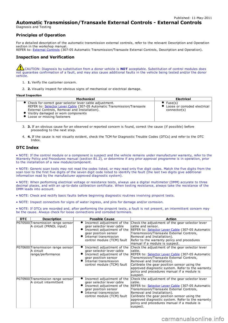
For a detail ed descripti on of the aut omati c transmis s ion external control s , refer t o t he rel evant Des cript ion and Operat ions ect ion i n t he works hop manual .REFER to: External Controls (307-05 Aut omati c Transmis s ion/Trans axle Ext ernal Cont rols , Des cript ion and Operat ion).
Inspection and Verification
CAUTION: Di agnos is by s ubs ti tut ion from a donor vehicle is NO T acceptabl e. Subs ti tut ion of cont rol modules doesnot guarant ee confirmat ion of a faul t, and may als o caus e addit ional fault s i n t he vehi cl e being t est ed and/or t he donorvehi cl e.
1. Verify t he cus t omer concern.1.
2. Vis ually ins pect for obvious s igns of mechani cal or electrical damage.2.
Visual InspectionMechanicalElectrical
Check for correct gear sel ect or l ever cable adjus t ment.REFER to: Select or Lever Cabl e (307-05 Aut omat ic Trans mi ss ion/TransaxleExternal Controls , Removal and Inst all at ion).Vis i bl y damaged or worn component sLoose or mis s ing fast eners
Fus e(s)Loos e or corroded el ect ri calconnector(s )
3. If an obvious cause for an obs erved or report ed concern is found, correct t he caus e (if pos s ible) beforeproceeding t o t he next s t ep.3.
4. If t he caus e is not vis ually evi dent , check t he TCM for Di agnos ti c Trouble Codes (DTCs) and refer t o t he DTCIndex.4.
DTC Index
• NOTE: If the control modul e or a component i s s us pect and the vehicle remains under manufacturer warrant y, refer t o theW arranty Pol icy and Procedures manual (s ect ion B1.2), or determine i f any pri or approval programme is in operat ion, pri ort o the ins tall ati on of a new module/component.
• NOTE: Generic scan t ool s may not read the codes li st ed, or may read only fi ve digit codes . Mat ch the five di git s from t hes can tool to the firs t fi ve di git s of the seven digi t code l is ted to ident ify t he faul t (t he las t t wo digi ts gi ve addi ti onalinformat ion read by the manufact urer approved diagnos t ic s ys tem).
• NOTE: W hen performing el ect ri cal volt age or resi s tance tes t s, al ways us e a digit al mult imet er (DMM) accurate to threedeci mal places , and wi th an up-to-date cali brat ion cert ificate. W hen t es ti ng res is t ance, always take t he res i st ance of t heDMM leads int o account.
• NOTE: Check and recti fy bas ic faul ts before beginni ng diagnos t ic rout ines i nvol vi ng pinpoint t es t s.
• NOTE: Ins pect connect ors for s igns of water ingres s , and pins for damage and/or corros ion.
• NOTE: If DTCs are recorded and, aft er performi ng the pi npoi nt tes ts , a fault is not present , an int ermi tt ent concern maybe t he caus e. Always check for loose connect ions and corroded terminals .
DT CDescriptionPossible CauseActionP070500Trans mi ss i on range s ensorA ci rcuit (PRNDL input)Incorrect adjus tment of t hegear s elector lever cabl eIncorrect adjus tment of t hegear posi ti on s ens orInt ernal t rans mi ss i oncontrol modul e (TCM) fault
Check t he adjust ment of the gear s elector levercable and sens or.REFER t o: Sel ect or Lever Cabl e (307-05 Automat icTrans mi s si on/Trans axl e External Controls ,Removal and Ins t al lat ion).Refer to t he warranty pol icy and proceduresmanual if a modul e i s s us pect.
P070600Trans mi ss i on range s ensorA ci rcuitrange/performance
Incorrect adjus tment of t hegear s elector lever cabl eIncorrect adjus tment of t hegear posi ti on s ens orInt ernal t rans mi ss i oncontrol modul e (TCM) fault
Check t he adjust ment of the gear s elector levercable.REFER t o: Sel ect or Lever Cabl e (307-05 Automat icTrans mi s si on/Trans axl e External Controls ,Removal and Ins t al lat ion).Cal ibrat e t he gear pos it ion s ens or us ing theapproved diagnos ti c sys t em. Refer to the warrant ypol icy and procedures manual i f a module iss us pect .
P070900Trans mi ss i on range s ensorA ci rcuit i ntermit tentIncorrect adjus tment of t hegear s elector lever cabl eIncorrect adjus tment of t hegear posi ti on s ens orInt ernal t rans mi ss i oncontrol modul e (TCM) fault
Check t he adjust ment of the gear s elector levercable.REFER t o: Sel ect or Lever Cabl e (307-05 Automat icTrans mi s si on/Trans axl e External Controls ,Removal and Ins t al lat ion).Cal ibrat e t he gear pos it ion s ens or us ing theapproved diagnos ti c sys t em. Refer to the warrant ypol icy and procedures manual i f a module iss us pect .
Page 1376 of 3229
Publi s hed: 11-May-2011
Automatic Transmission/Transaxle External Controls - Selector Lever Cable
Adjustment
General Procedures
Check the operat ion of t he t ransmis s ion s elector l ever.1.
Remove t he gear s elector knob.
Refer t o: Sel ect or Lever Knob (307-05, Removal and Ins tall ati on).
2.
3.
4. CAUTION: Make s ure that the sel ect or leverand t he gears hi ft mechanis m are i n t he park (P)pos it ion.
Releas e t he s el ect or cable adjus ter.
4.
5. CAUTION: Make s ure that the sel ect or leverand t he gears hi ft mechanis m are i n t he park (P)pos it ion.
5.
Page 1378 of 3229
Publi s hed: 11-May-2011
Automatic Transmission/Transaxle External Controls - Selector Lever
Assembly
Removal and Inst all ati on
Removal
Remove t he fl oor consol e.
Refer t o: Fl oor Cons ole (501-12 Inst rument Panel and Cons ole,
Removal and Ins tall ati on).
1.
Pos it ion t he transmis s ion s elector lever int o PARK. Depres s and hold the s elector cable ball joint rel eas e but ton,
us ing a lever carefully dis connect t he cable. Releas e t he cabl e.2.
T orque: 10 Nm 3.
Installation To i nst all , revers e t he removal procedure.
1.
Page 1379 of 3229
Publi s hed: 11-May-2011
Automatic Transmission/Transaxle External Controls - Selector Lever Cable
Removal and Inst all ati on
Removal
CAUTION: Make s ure that the sel ect or lever and t he gears hift mechanis m are in t he park (P) posi ti on.
1. W ARNING: Make sure t o s upport the vehicle wit h axles tands .
Rais e and s upport t he vehi cl e.
1.
Remove t he dri ves haft .
Refer t o: Dri ves haft - Vehicles W it hout : Dies el Part icul ate Fi lt er(DPF) (205-01 Driveshaft, Removal and Ins tal lati on).
2.
Remove t he fl oor consol e.
Refer t o: Fl oor Cons ole (501-12 Inst rument Panel and Cons ole,Removal and Ins tall ati on).
3.
Remove t he air cleaner as s embly.
Refer t o: Air Cleaner (303-12A Intake Ai r Dis tribut ion and Fil tering -I6 3.2L Pet rol, Removal and Ins t al lat ion).
4.
Remove t he ins trument panel, l ower trim panel s.5.
6.