2006 LAND ROVER FRELANDER 2 change time
[x] Cancel search: change timePage 625 of 3229
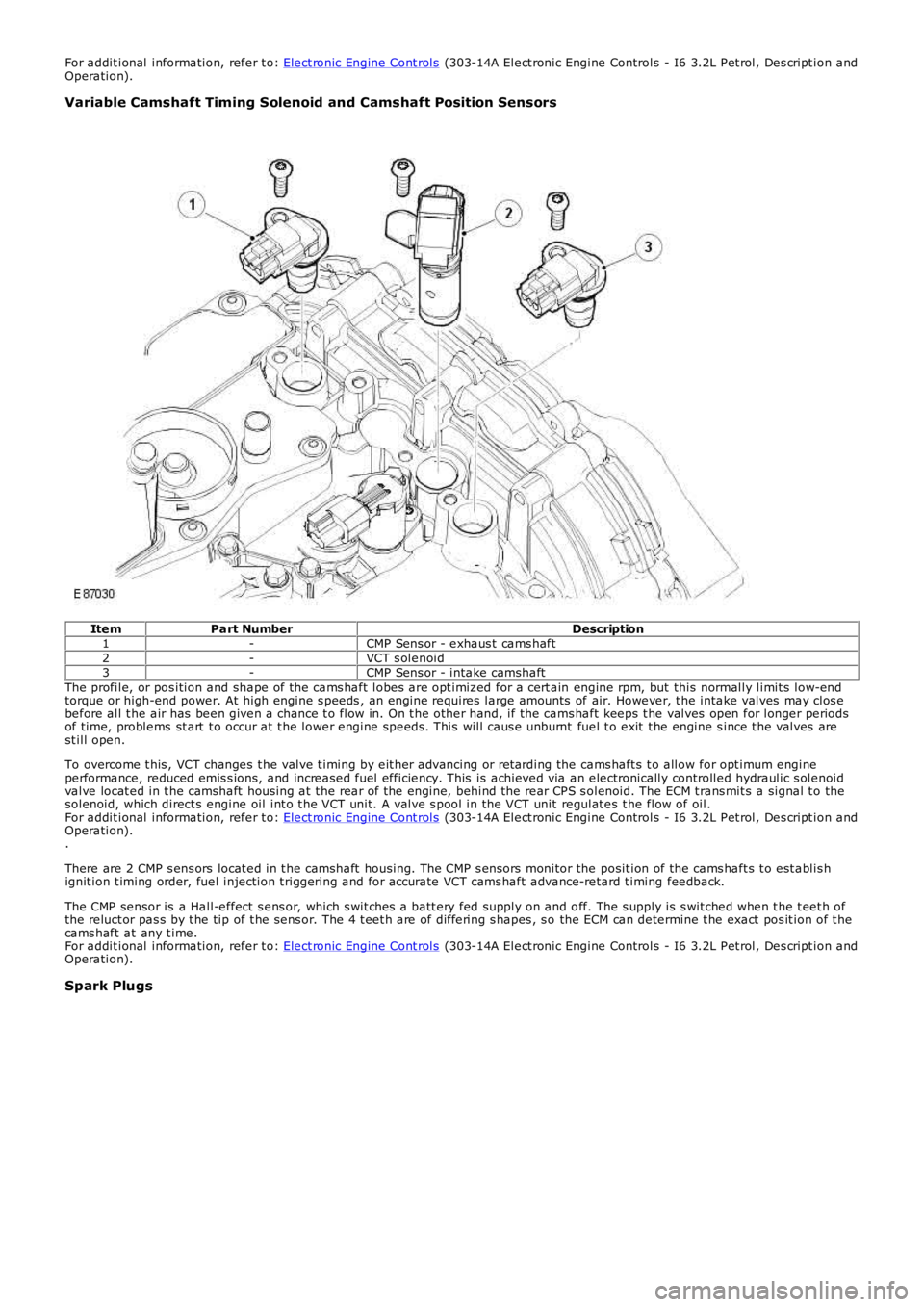
For addit ional information, refer t o: Elect ronic Engine Cont rols (303-14A Elect ronic Engine Controls - I6 3.2L Pet rol, Des cript ion andOperation).
Variable Camshaft Timing Solenoid and Camshaft Position Sensors
ItemPart NumberDescription1-CMP Sens or - exhaus t cams haft2-VCT s olenoid3-CMP Sens or - intake camshaftThe profile, or pos ition and shape of the cams haft lobes are opt imiz ed for a cert ain engine rpm, but this normally limit s low-endtorque or high-end power. At high engine s peeds , an engine requires large amounts of air. However, t he intake valves may clos ebefore all t he air has been given a chance t o flow in. On t he other hand, if the cams haft keeps t he valves open for longer periodsof time, problems st art t o occur at t he lower engine speeds . This will caus e unburnt fuel t o exit t he engine s ince t he valves arest ill open.
To overcome t his , VCT changes t he valve t iming by eit her advancing or ret arding the cams haft s t o allow for opt imum engineperformance, reduced emis s ions, and increased fuel efficiency. This is achieved via an electronically controlled hydraulic s olenoidvalve locat ed in t he camshaft housing at t he rear of t he engine, behind the rear CPS s olenoid. The ECM t rans mit s a signal t o thesolenoid, which direct s engine oil int o t he VCT unit. A valve s pool in the VCT unit regulat es t he flow of oil.For addit ional information, refer t o: Elect ronic Engine Cont rols (303-14A Elect ronic Engine Controls - I6 3.2L Pet rol, Des cript ion andOperation)..
There are 2 CMP s ens ors locat ed in t he camshaft housing. The CMP s ensors monitor the posit ion of the cams haft s t o est ablis hignit ion t iming order, fuel injection t riggering and for accurate VCT cams haft advance-retard t iming feedback.
The CMP sensor is a Hall-effect s ens or, which s wit ches a batt ery fed supply on and off. The s upply is s wit ched when t he t eet h ofthe reluct or pas s by t he tip of t he sens or. The 4 t eet h are of differing s hapes , s o the ECM can determine t he exact pos it ion of t hecams haft at any t ime.For addit ional information, refer t o: Elect ronic Engine Cont rols (303-14A Elect ronic Engine Controls - I6 3.2L Pet rol, Des cript ion andOperation).
Spark Plugs
Page 1654 of 3229
a utomati c control.
Air distri buti on can be re turned t o automatic control by pres sing the 'AUTO' swi tch loca ted in the ce nte r of the blower motorrotary controller. Thi s wi ll ill uminate the 'AUTO' LED and allow t he ATC module to control a ir di stribution in line wit h it s'comfort' algorithm
Air distri buti on is control led by 2 air dist ribution doors. The ATC module control s the position of the air dis tribution doors byprovi ding LIN bus me ssa ges to t he door ste pper motors . Ha ll ef fect sensors located wit hin the stepper mot ors inform t he ATCmodule t hat moveme nt of the st epper motors is taking place.
ECON - Single Zone Manual System
P ress ing the 'ECO N' moment ary swit ch on the control pa nel will swi tch off t he A/C s yste m. W he n s elected, the ATC modulewill t rans mit a mess age ove r the high speed CAN bus to the ECM re que sting the A/C compressor is dis able d. The ECMdisables the compres sor by de-e nergizing the A/C compress or control re lay loca ted in the BJB. The tell-tale LED in the swit chwill i lluminat e to ale rt the ve hicl e occupants tha t the system is in 'ECO N' mode .
W he n 'ECON' mode i s se lect ed, tempera ture control is s till a vai lable but no cooling of i ntake ai r wi ll ta ke place . The minimumoutput a ir te mpe rature f rom the sys tem will be ambient air tempera ture plus any heat pick up in the ai r int ake pat h.
A/C can be s witched back on by pres sing the 'ECON' swi tch a se cond time. This will als o extinguish the 'ECON' LED.
Stop/Sta rt Ve hicl es - From 2010 MY
From 2010 MY , t he 'ECON' switch wi ll be labeled ‘A/C’ to pre vent confus ion with the ‘Eco’ switch which operates the‘Stop/Sta rt’ a nd 'Gea r Change Indica tor' syst ems .For a ddit iona l inf ormation, re fer to: Starting Sys tem (303-06C Start ing Syst em - TD4 2.2L Diese l, Vehicles Buil t From:01-03-2009, Des cript ion and Ope rati on).
ECON - Dual Zone Automatic System
P ress ing the 'ECO N/O FF' momentary swi tch in the control pa nel will swi tch off t he A/C s yste m. W he n s elected, the ATCmodule will t rans mit a mess age ove r the high speed CAN bus to the ECM re que sting the A/C compress or is dis able d. The ECMdisables the compres sor by de-e nergizing the A/C compress or control re lay loca ted in the BJB. The 'ECO N' t ell-tale LED in t hes witch will il lumi nate to alert the ve hicle occupa nts that the sys tem is i n 'ECON' mode.
W he n 'ECON' mode i s se lect ed, tempera ture control is s till a vai lable but no cooling of i ntake ai r wi ll ta ke place . The minimumoutput a ir te mpe rature f rom the sys tem will be ambient air tempera ture plus any heat pick up in the ai r int ake pat h.
A second pre ss of the 'ECON/OFF' switch wil l ext inguish the 'ECO N' LED and illuminate the 'OFF' LED. W hen in 'OFF' mode t heATC module sets the blower mot or s pee d to 0. Air distri buti on i nto the cabi n wi ll remai n as pre viously sele cted. Al l LED's ont he control pane l wil l be ext inguishe d, a lthough night ti me illumina tion will remain acti ve.
• NO TE: W he n in 'OFF' mode , the he ated se at, heat ed windshie ld a nd heat ed rear window functions wi ll st ill be availa ble.
A thi rd press of t he 'ECO N/O FF' s wit ch re turns the s yste m to norma l (A/C) operation and extinguishes t he 'OFF' LED. Thes yste m can be re turned to a utomati c operat ion at a ny t ime by press ing the 'AUTO' swit ch mounted in t he cent ral (blowermotor) rotary control ler.
Stop/Sta rt Ve hicl es - From 2010 MY
From 2010 MY , t he 'ECON' switch wi ll be labeled ‘A/C’ to pre vent confus ion with the ‘Eco’ switch which operates the‘Stop/Sta rt’ a nd 'Gea r Change Indica tor' syst ems .For a ddit iona l inf ormation, re fer to: Starting Sys tem (303-06C Start ing Syst em - TD4 2.2L Diese l, Vehicles Buil t From:01-03-2009, Des cript ion and Ope rati on).
Programmed Defrost
The programmed def rost function is only ava ilable on ve hicl es fi tted wit h a dua l zone heati ng, vent ilat ion a nd A/C syst em.The f unction is s elected by press ing the 'PRO G' moment ary swit ch on the control pa nel. W hen s ele cted, the ATC moduleprovi des maximum winds hie ld de fros ting/de mist ing by confi guri ng t he s yste m a s follows:
'AUTO ' mode offIntake air set to fres h airAir di stribution se t to windshieldBlowe r motor spe ed s et t o maximumHeate d winds hiel d onRear window hea ter on.
W he n progra mmed defrost is sel ecte d, t he s et t emperat ure will remain unchanged. Programme d de fros t ca n be cancell ed bya ny of the following met hods:
P ress ing any air distribut ion moment ary swit chP ress ing the 'AUTO' s witch locate d in the center of t he blowe r motor rot ary cont rolle rP ress ing the 'PRO G' momenta ry s witch a second time .
• NO TE: Blower motor speed can be adjuste d wi thout te rmi nating programmed defrost.
Windshield Heater
The windshie ld heate r comprises 2 heate r el eme nts , LH and RH, bonded be twee n the glass laminat ions . The s yste m iss witched on by press ing the momentary swi tch l ocat ed on t he control panel . W hen selected, the ATC module t rans mits aheat ing request on t he high spe ed CAN bus to t he CJB. On rece ipt of the messa ge, the CJB ene rgiz es t he windshie ld heate rrelay loca ted in t he BJB by provi ding a ground path for t he relay coi l. The energized rela y provides a ba ttery fe ed t o bothheat er el eme nts . Aft er a period of 4 minutes the ATC module re moves t he request for windshie ld heati ng. The CJB the npowe rs down the windshield hea ter by re moving the ground pat h for the rel ay coil.
The ATC module will only reques t wi ndshield he ater ope rati on if the engine is runni ng. An e ngi ne s tatus si gnal is provi ded tot he ATC module by t he ECM over the high speed CAN bus.
Page 1920 of 3229
10-RH s i de turn s ignal lamp
11-Licens e pl ate lamps
12-LH rear l amp as s embl y13-RH rear lamp as s embly
14-LH headlamp as s embly
15-AFS cont rol module16-Headl amp l evel ing mot or
17-RH headlamp as s embly
18-Steering wheel modul e19-LH s t eering column mult ifunct ion s wit ch
20-High mount ed s top lamp
21-Central Junct ion Box (CJB)22-Revers e s wit ch (manual transmis si on only)
23-Stoplamp s wit ch
24-Rain/light s ensor25-Hazard flas her s wi tch
26-Light s wit ch modul e
27-Fuse 15A (F33)
CENTRAL JUNCTION BOX (CJB)
The CJB receives exteri or li ght ing relat ed inputs from t he fol lowing s wi tches:
Light s wit ch modul e- Side l amp pos it ion- Headlamp pos it ion- Automat ic (AUTO) posi ti on (if fi tt ed)- Front fog lamp swi tch (if fit ted)- Rear fog l amp s wit ch- Dimmer cont rol- Headlamp l evel ing control (if fit ted).Brake s wi tchLH s t eering column mult ifunct ion s wit ch for t urn si gnal i ndi cat ors and hi gh beam/headl amp flas hHazard flas her s wi tchRain/light s ensor (LIN si gnal ).
Circuit Protection
Two 60 Amp fus ibl e li nks in t he batt ery junct ion box protect the power feed to the CJB LH and RH li ght ing ci rcuit sres pect ively. All ext erior l ighti ng ci rcuit s are prot ect ed by Field Effect Trans is t ors (FETs ), l ocat ed in the CJB, which candetect overloads and s hort circuit s .
The FETs res pond to heat generated by increased current fl ow caus ed by a s hort ci rcuit . On a normal ci rcuit t his woul dcaus e t he fus e to bl ow. The FETs respond t o t he heat i ncrease and di s connect t he s uppl y t o t he affect ed ci rcuit . W hen t hefaul t is rect ified or t he FET has cool ed, t he FET wil l res et and operate t he circui t normall y. If t he faul t pers is ts the FET wi llcycle, di sconnect ing and reconnect ing t he power supply. The CJB s tores fault codes which can be ret rieved usi ng a LandRover approved diagnost ic sys tem. The fault code wil l identi fy t hat there is a fault on a part icular out put which as si s t infaul t det ect ion.
Alarm Indications
The exteri or li ght ing s ys tem is us ed for al arm arm and dis arm reques ts . W hen t he driver l ocks or unlocks the vehicle, avis ual i ndicat ion of a s uccess ful l ock or unlock reques t is di spl ayed t o t he dri ver by the hazard flas hers operat ing a numberof ti mes .For addit ional informat ion, refer t o: Anti -Theft - Act ive (419-01A Anti -Theft - Acti ve, Des cri pt ion and Operati on).
Lights On Warning chime
W hen t he i gni ti on in the off (power mode 0) or auxi liary (power mode 4) mode and the l ighti ng cont rol rotary swit ch is i nt he si de lamp or headlamp posi ti on, a warning chime wi ll s ound i f the driver's door is opened. This indicates t o t he dri vert hat t he exterior li ght s have been left on. The chime is generat ed from t he i ns t rument clus ter s ounder on receipt of ali ght s on s i gnal , a door open s ignal and an ignit ion swi tch off s ignal from t he CJB on the hi gh s peed CAN bus.
Crash Signal Activation
W hen a crash s ignal i s t rans mit ted from t he Rest rai nts Cont rol Modul e (RCM), t he CJB act ivat es the hazard flas hers andt he turn s ignal indicators in t he i ns t rument clus ter. The hazard fl ashers wil l continue to operate unt il t he ignit ion mode ischanged t o t he auxi liary power mode 4or the off power mode 0 or the RCM no longer trans mi ts the cras h si gnal .For addit ional informat ion, refer t o: Air Bag and Safet y Belt Pretens ioner Supplement al Res traint Syst em (SRS) (501-20BSuppl ement al Rest rai nt Sys tem, Des cri pti on and Operati on).
Headlamp Timer
The CJB cont rol s a headl amp t imer funct ion whi ch allows the headlamps t o remain on for a peri od of ti me after leaving t hevehi cl e. Thi s is a dri ver conveni ence feat ure which il lumi nat es t he dri veway after leaving t he vehicle.
This feat ure can onl y be acti vat ed by pulli ng t he high beam ' flas h-t o-pas s' on t he LH s t eering column mult ifunct ion s wi tch.It can be deacti vat ed eit her by ti ming out or by pull ing t he mul ti funct ion swi tch again.
The default s ett ing can be changed by a Land Rover or authorized deal er . The default t imi ng is s et t o 30s but can bechanged t o 0s (OFF), 30s (defaul t), 60s , 90s , 120s , 150s and 180s .For addit ional informat ion, refer t o: Informat ion and Mes s age Cent er (413-08 Informat ion and Mes s age Cent er, Des cript ionand Operat ion).
Page 2454 of 3229
1
2
3
1
2
3
4
1
2
3
4
5
CarlineMarketSeat positionAutomatic Locking Retractor InstalledFrom Model Year
Range Rover Evoque (L358)AllDriverNo2011
Range Rover Evoque (L358)ROWPas sengerNo2011Range Rover Evoque (L358)USPas sengerY es2011
Range Rover Evoque (L358)ROWRow 2No2011
Range Rover Evoque (L358)USRow 2Y es2011Range Rover (L322)AllDriverNo2003
Range Rover (L322)ROWPas sengerNo2003
Range Rover (L322)USPas sengerY es2003Range Rover (L322)ROWRow 2No2003
Range Rover (L322)USRow 2Y es2003
The automatic locking retractor function is a feature t o s ecure a child s eat or heavy load t o t he seat
ActivationDeactivation• NOTE: W hen aut omati c locking retract or is acti vat ed, no further webbi ngcan be drawn from t he s afet y bel t ret ractor, pri or t o di sengagement of t heautomat ic l ocki ng. This can be mis t aken as a jammed safety bel t ret ractor
Acti vat ed by t otal ext ract ion of t he webbi ng
Aut omat ic l ocking retract or is deacti vat ed byallowi ng the webbi ng to ret ract unt il t hecl icking s t ops (clos e t o park pos it ion)
W hen act ivated t he automat ic l ocki ng ret ractor is identi fi ed by a cli ckingnois e duri ng webbing retract ionW hen deact ivated the aut omati c locki ngret ractor s afet y bel t changes s tat e, from astatic s afet y belt t o an automatic s afety bel t
Safety Belt Locking Test
W i th the vehicle st ati onary and on l evel ground t ake fi rm hold of t he s afety bel t webbi ng (on the t ongue si de of the uppers afety bel t anchor) and wit hdraw s harply, the retractor should lock. Preventi ng further webbi ng rel eas e (repeat this test3 times). Any s afety bel t ret ractor whi ch fail s t o lock must not be used and a new safety belt must be installed.
DTC Index
For a li st of di agnos ti c troubl e codes that coul d be l ogged on t his vehicle, pl eas e refer t o Sect ion 100-00 or for removaland ins t al lat ion/des cript ion and operat ion s ee Secti on 501-20
Diagnostic Guide Inertia Reel Safety Belts
PINPOINT TEST A : BACKLOCK
T ESTCONDIT IONSDET AILS/RESULT S/ACT IONS
A1: BACKLOCK
Vi suall y i ns pect the condi ti on of the sus pect s afet y belt
Draw a maxi mum of 20mm of t he webbi ng from t he s afet y belt ret ract or wit h moderat e force. Thenrelease the webbi ng
Check for correct operat ion t wice
Does t he webbi ng move freely t hen ret ract correct ly?YesNo furt her act ion requi redNoFor fi rs t row s afet y bel t GO to Pi npoi nt Tes t C. For second and thi rd row s afet y belt s GO toPi npoint Tes t B.
PINPOINT TEST B : WEBBING-TRAPPED IN SEAT
T ESTCONDIT IONSDET AILS/RESULT S/ACT IONS
B1: WEBBING-T RAPPED IN SEAT
Vis ual ly i nspect the condit ion of t he s uspect safety bel t
Li ft t he s eat bas e or release the s eat backres t as requi red
Free t he trapped webbi ng, all ow t he webbing t o ret ract Note: If the automatic locking retractor isactivated, allow the w ebbing to retract until the clicking stops
Check for correct operat ion twice
Does t he webbing move freel y then retract correct ly?YesNo further acti on requiredNoGO t o Pinpoint Tes t C.
PINPOINT TEST C : SAFETY BELT RETRACTOR-WEBBING G UIDE LOOSE
T ESTCO NDIT IONSDET AILS/RESULT S/ACT IONS
C1: SAFET Y BELT RET RACT OR -WEBBING GUIDE LOOSE
Refer to 501-20 removal and ins t al lat ion s ect ion of t he works hop manual, remove any trim panel srequired to expos e t he D l oop (anchor point ) and s afety bel t ret ractor
Check t he webbing i s not trapped or t wis t ed and is centrall y located on t he s afet y belt ret ract ors pi ndl e
Att empt to wit hdraw t he webbing from t he safety bel t ret ractor NOT E: If the safety belt webbing isjammed, the automatic locking retractor could be engaged
To rel eas e t he automat ic locki ng ret ractor, manual ly wi nd t he webbi ng onto t he s pindle unt il t heaut omat ic l ocking retract or deacti vat es (cl icking s t ops )Ful ly ext ract webbi ng
Page 2743 of 3229
23
Quick start
R
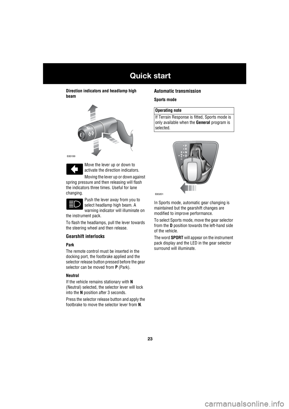
Direction indicators and headlamp high
beam
Move the lever up or down to
activate the direction indicators.
Moving the lever up or down against
spring pressure and then releasing will flash
the indicators three times. Useful for lane
changing.
Push the lever away from you to
select headlamp high beam. A
warning indicator will illuminate on
the instrument pack.
To flash the headlamps, pull the lever towards
the steering wheel and then release.
Gearshift interlocks
Park
The remote control must be inserted in the
docking port, the footbrake applied and the
selector release button pr essed before the gear
selector can be moved from P (Park).
Neutral
If the vehicle remains stationary with N
(Neutral) selected, the selector lever will lock
into the N position after 3 seconds.
Press the selector rele ase button and apply the
footbrake to move the selector lever from N.
Automatic transmission
Sports mode
In Sports mode, automatic gear changing is
maintained but the gearshift changes are
modified to improve performance.
To select Sports mode, move the gear selector
from the D position towards the left-hand side
of the vehicle.
The word SPORT will appear on the instrument
pack display and the LED in the gear selector
surround will illuminate.
E83199
Operating note
If Terrain Response is fi tted, Sports mode is
only available when the General program is
selected.
E83201
Page 2750 of 3229
30
Quick start
L
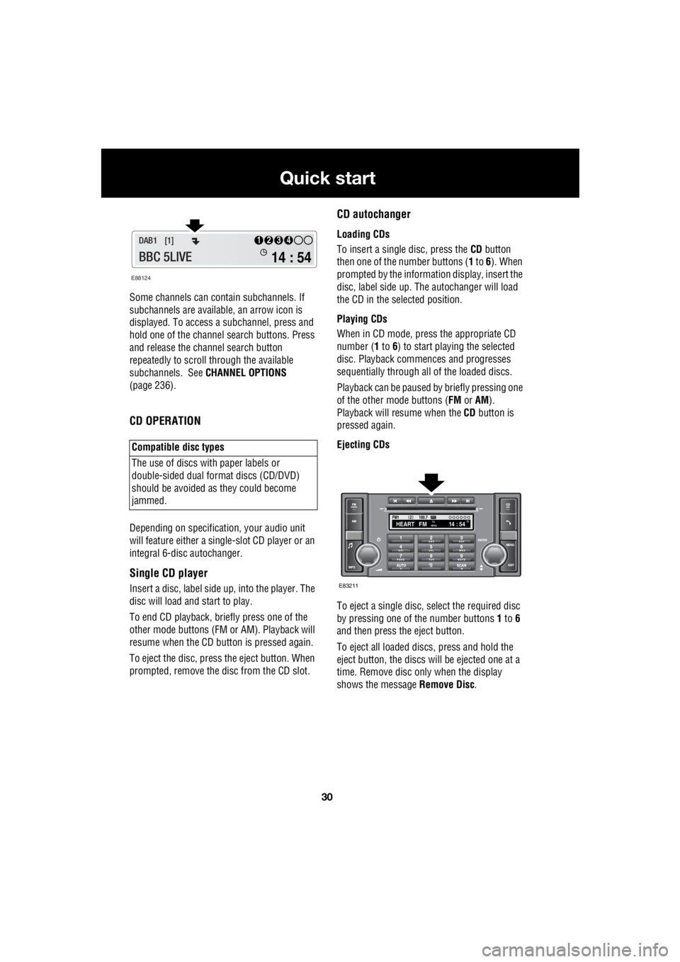
Some channels can co ntain subchannels. If
subchannels are availabl e, an arrow icon is
displayed. To access a subchannel, press and
hold one of the channel search buttons. Press
and release the channel search button
repeatedly to scroll through the available
subchannels. See CHANNEL OPTIONS
(page 236).
CD OPERATION
Depending on specification, your audio unit
will feature either a single- slot CD player or an
integral 6-disc autochanger.
Single CD player
Insert a disc, label side up, into the player. The
disc will load and start to play.
To end CD play back, briefly press one of the
other mode buttons (FM or AM). Playback will
resume when the CD button is pressed again.
To eject the disc, press the eject button. When
prompted, remove the disc from the CD slot.
CD autochanger
Loading CDs
To insert a single disc, press the CD button
then one of the number buttons ( 1 to 6). When
prompted by the information display, insert the
disc, label side up. The autochanger will load
the CD in the selected position.
Playing CDs
When in CD mode, press the appropriate CD
number ( 1 to 6) to start playing the selected
disc. Playback commences and progresses
sequentially through all of the loaded discs.
Playback can be paused by briefly pressing one
of the other mode buttons ( FM or AM).
Playback will re sume when the CD button is
pressed again.
Ejecting CDs
To eject a single disc, select the required disc
by pressing one of the number buttons 1 to 6
and then press the eject button.
To eject all loaded discs, press and hold the
eject button, the discs will be ejected one at a
time. Remove disc only when the display
shows the message Remove Disc.
Compatible disc types
The use of discs with paper labels or
double-sided dual format discs (CD/DVD)
should be avoided as they could become
jammed.
E88124
14 : 54
1234DAB1 [1]
BBC 5LIVE
100.7
2FM114 : 54TA
NEWSHEART FMPTY
E83211
Page 2761 of 3229
41
Keys and remote controls
R
USING THE REMOTE CONTROL
Remote control
Note: The operational range of the remote
control will vary considerably depending on
atmospheric conditions and interference from
other transmitting devices.
The vehicle is supplied with two remote
controls, but up to six can be programmed to
the vehicle at any one time.
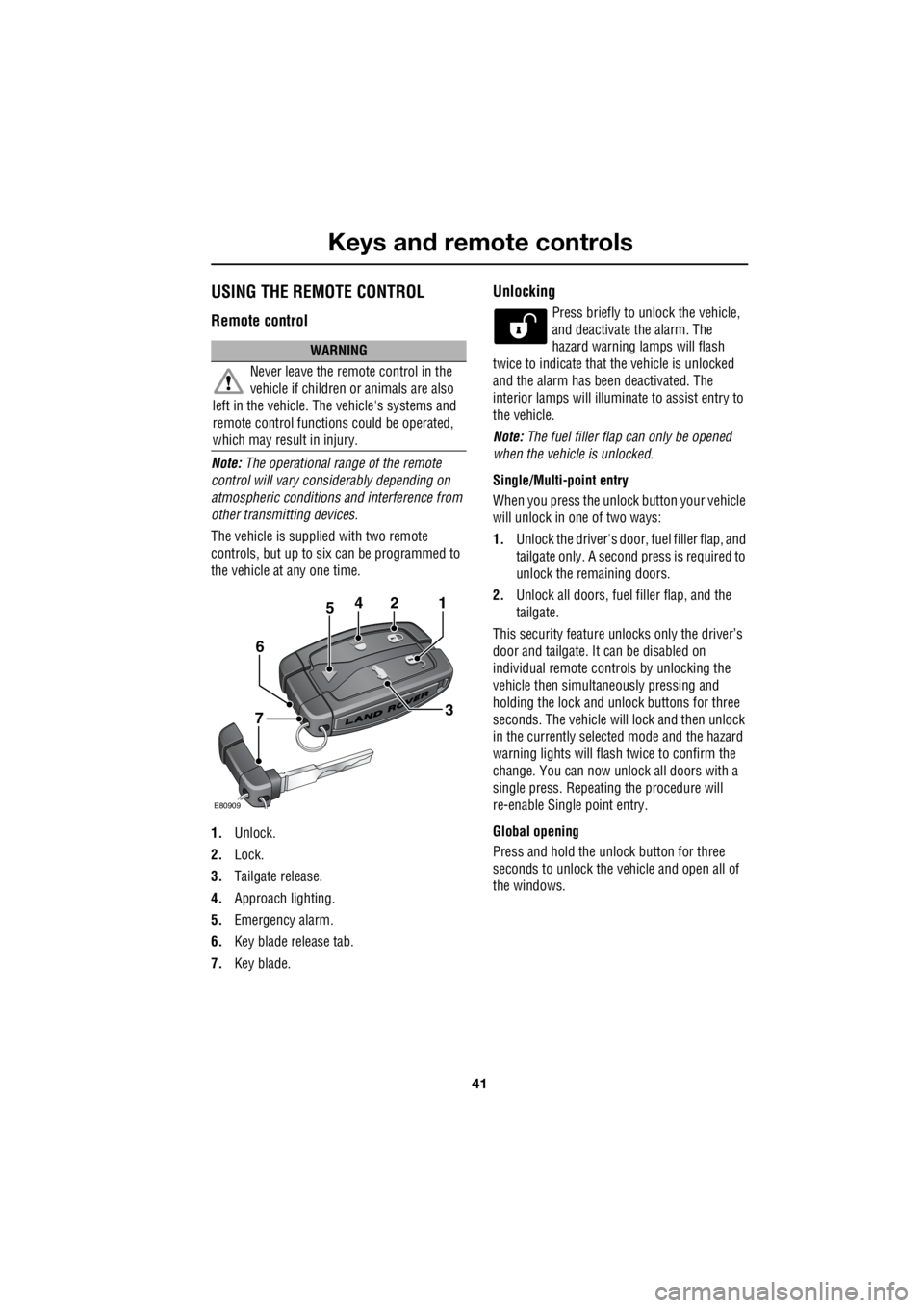
1. Unlock.
2. Lock.
3. Tailgate release.
4. Approach lighting.
5. Emergency alarm.
6. Key blade release tab.
7. Key blade.
Unlocking
Press briefly to unlock the vehicle,
and deactivate the alarm. The
hazard warning lamps will flash
twice to indicate that the vehicle is unlocked
and the alarm has been deactivated. The
interior lamps will illuminate to assist entry to
the vehicle.
Note: The fuel filler flap can only be opened
when the vehicle is unlocked.
Single/Multi- point entry
When you press the unlock button your vehicle
will unlock in one of two ways:
1. Unlock the driver's door, fuel filler flap, and
tailgate only. A second press is required to
unlock the remaining doors.
2. Unlock all doors, fuel filler flap, and the
tailgate.
This security feature unlocks only the driver’s
door and tailgate. It can be disabled on
individual remote controls by unlocking the
vehicle then simultaneously pressing and
holding the lock and unlock buttons for three
seconds. The vehicle will lock and then unlock
in the currently selected mode and the hazard
warning lights will flas h twice to confirm the
change. You can now unlock all doors with a
single press. Repeating the procedure will
re-enable Single point entry.
Global opening
Press and hold the unlock button for three
seconds to unlock the ve hicle and open all of
the windows.
WARNING
Never leave the remote control in the
vehicle if children or animals are also
left in the vehicle. The vehicle's systems and
remote control functions could be operated,
which may result in injury.
2
E80909
451
3
6
7
Page 2773 of 3229
53
Seats
R
Raising the rear seats
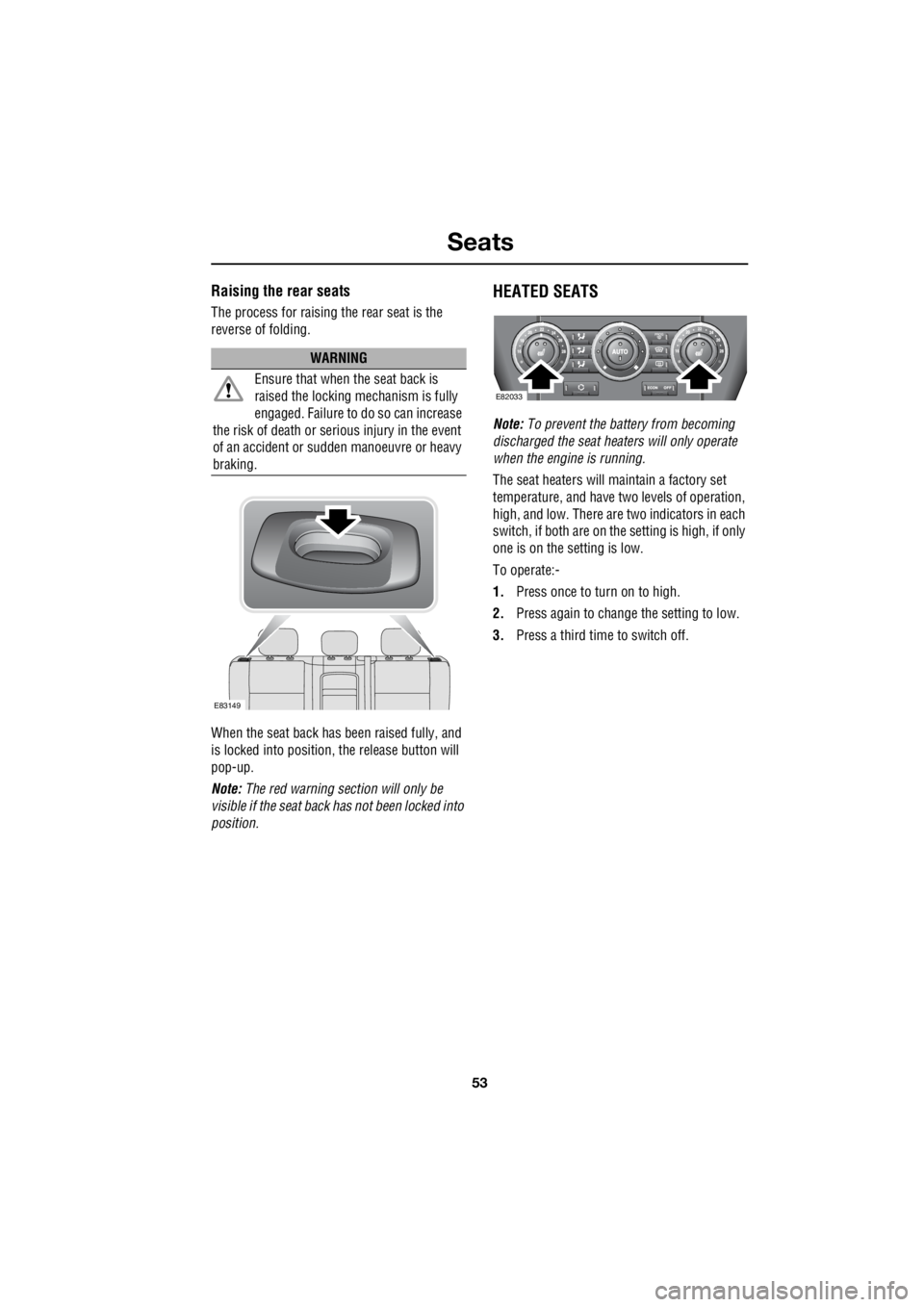
The process for raising the rear seat is the
reverse of folding.
When the seat back has been raised fully, and
is locked into position, the release button will
pop-up.
Note: The red warning section will only be
visible if the seat back has not been locked into
position.
HEATED SEATS
Note: To prevent the battery from becoming
discharged the seat heaters will only operate
when the engine is running.
The seat heaters will maintain a factory set
temperature, and have two levels of operation,
high, and low. There are two indicators in each
switch, if both are on the setting is high, if only
one is on the setting is low.
To operate:-
1. Press once to turn on to high.
2. Press again to change the setting to low.
3. Press a third time to switch off.
WARNING
Ensure that when the seat back is
raised the locking mechanism is fully
engaged. Failure to do so can increase
the risk of death or serious injury in the event
of an accident or s udden manoeuvre or heavy
braking.
E83149
E82033