Page 17 of 3229

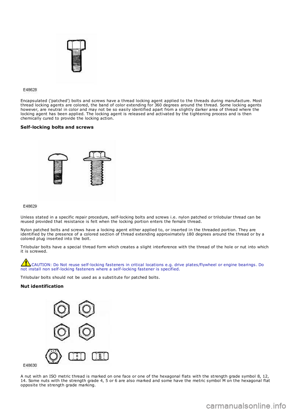
Encaps ulated ('pat ched') bolt s and s crews have a t hread l ocking agent appl ied t o t he t hreads during manufact ure. Mos tt hread locking agent s are col ored, the band of color extending for 360 degrees around the t hread. Some l ocking agentshowever, are neutral in color and may not be s o eas il y identi fi ed apart from a s li ght ly darker area of thread where t helocking agent has been appli ed. The l ocking agent is releas ed and acti vat ed by t he ti ght ening proces s and is thenchemical ly cured to provide t he locking acti on.
Self-locking bolts and screws
Unles s s tat ed in a s peci fic repair procedure, sel f-locki ng bolt s and s crews i.e. nylon patched or tril obul ar t hread can bereus ed provided t hat res is t ance i s fel t when the locki ng port ion enters t he femal e thread.
Nylon pat ched bolt s and s crews have a l ocking agent eit her appli ed t o, or i ns erted in t he threaded porti on. They areidenti fi ed by t he pres ence of a colored s ect ion of t hread extending approximat ely 180 degrees around the t hread or by acol ored pl ug ins ert ed int o t he bol t.
Tri lobular bolt s have a s pecial t hread form which creates a s light i nt erference wit h t he t hread of the hol e or nut i nto whichit i s s crewed.
CAUTION: Do Not reuse sel f-locki ng fas t eners in crit ical locat ions e.g. drive pl at es/flywheel or engine beari ngs . Donot ins tal l non s elf-locki ng fas teners where a sel f-locki ng fas t ener i s s pecified.
Tri lobular bolt s s hould not be used as a s ubs t it ut e for pat ched bol ts .
Nut identification
A nut wi th an ISO metric t hread i s marked on one face or one of the hexagonal fl ats wit h t he st rengt h grade s ymbol 8, 12,14. Some nuts wi th the st rength grade 4, 5 or 6 are als o marked and s ome have the metric s ymbol M on t he hexagonal fl atoppos it e t he s trengt h grade marking.
Page 420 of 3229
Publi s hed: 11-May-2011
Front Disc Brake -
General SpecificationItemSpecification
Front dis cVenti lated
Front disc diameter:3.2 Pet rol316 mm (12.4 i n)
2.2 Dies el300 mm (11.8 i n)
Front dis c t hicknes s new (All engines )28 mm (1.10 i n)Service l imit (All engi nes )26 mm (1.024 i n)
Maximum dis c run-out - dis c ins t al led0.080 mm (0.003 i n)
Pad mi nimum thi cknes s2 mm (0.078 i n)Pis t on diamet er60 mm (2.362 i n)
Torque SpecificationsDescriptionNmlb-ft
Brake cali per bl eed screw86
Brake cali per mount ing pl at e t o wheel knuckle bolt s *200148Brake cali per gui de pin bolt s2821
Brake di sc dus t s hield bol ts107
Brake di sc Torx s crew3526Brake flexi hose uni on to cal iper3224
Brake hos e retaini ng bracket t o damper bol t2216
* New nuts/bolts must be fitted
Page 433 of 3229
Publi s hed: 11-May-2011
Rear Disc Brake -
General SpecificationItemSpecification
Rear disc:
3.2 Pet rol engineVent il at ed2.2 Dies el engineSol id
Rear disc diameter:
Venti lat ed302 mm (11.9 in)Soli d302 mm (11.9 in)
Rear disc thickness new :
Venti lat ed20 mm (0.79 in)Soli d12 mm (0.47 in)
Service limit:
Venti lat ed18 mmSoli d10 mm
Pad mi nimum thi cknes s2 mm
Maximum dis c run out - Dis c ins t al led0.080 mm
Torque Specifications
DescriptionNmlb-ftBrake cali per bl eed screw107
Brake cali per fixed carrier t o wheel knuckl e bolt s*11081
Brake cali per gui de pin bolt s3022Brake di sc dus t s hield bol ts1310
Brake di sc Torx s crew3526
Brake flexi hose uni ons to cali per1511Brake hos e retaini ng bracket t o wheel knuckle bolt2216
* New nuts/bolts must be installed
Page 570 of 3229
Publi s hed: 11-May-2011
Steering Column -
General SpecificationItemSpecification
Upper columnManual column wit h t ilt and reach adjust ment
Torque Specifications
DescriptionNmlb-ft
Heats hiel d lower bolt s (2) to s t eel pi ni on t ower3.22.3Heats hiel d upper bolt (1) t o plas ti c s eal2.41.77
St eering column bol ts2518
St eering wheel bol t4835Univers al joi nt to st eering gear bolt *2518
* New nuts/bolts must be fitted
Page 604 of 3229

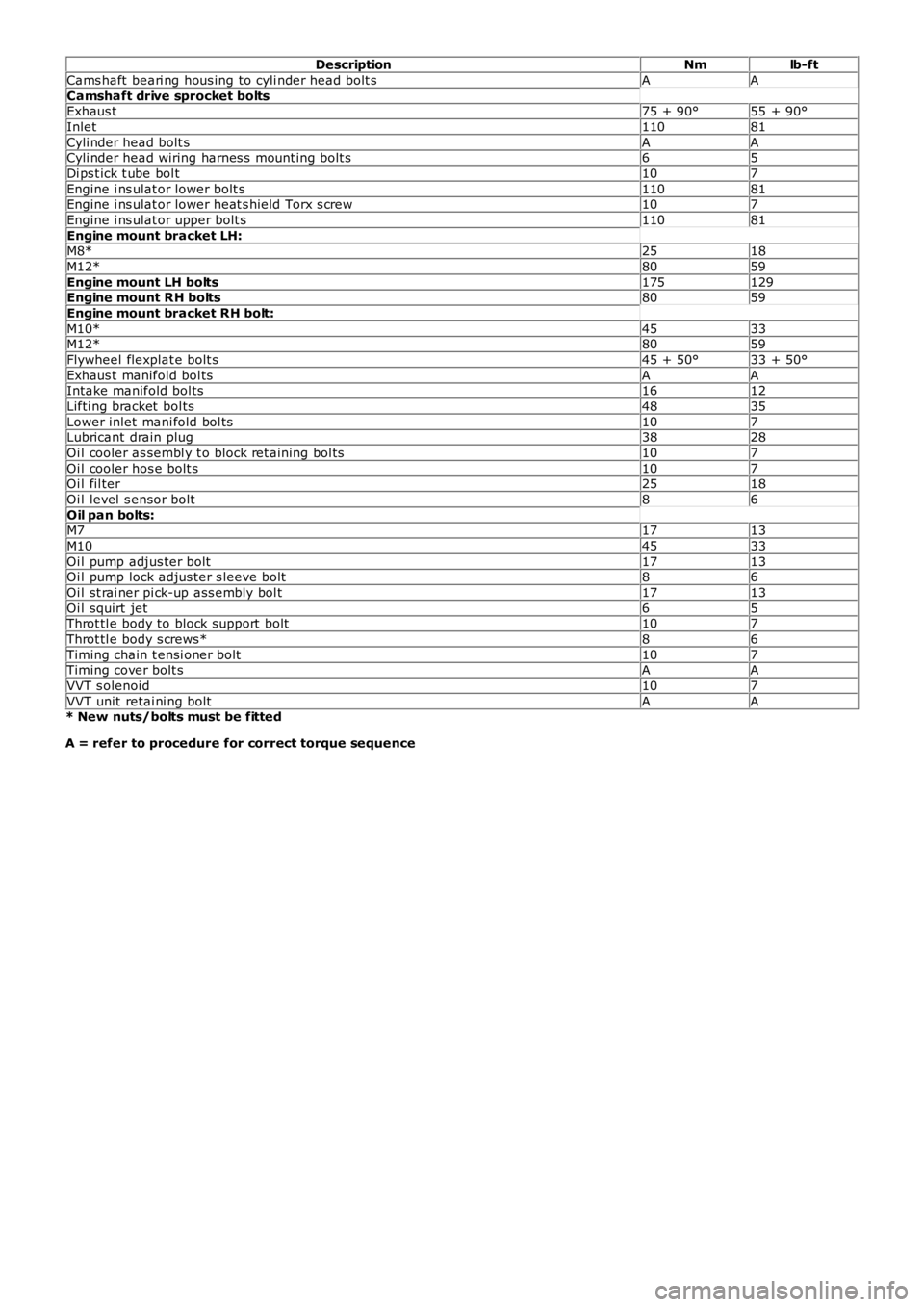
DescriptionNmlb-ft
Cams haft beari ng hous ing to cyli nder head bolt sAA
Camshaft drive sprocket boltsExhaus t75 + 90°55 + 90°
Inlet11081
Cyli nder head bolt sAACyli nder head wiring harnes s mount ing bolt s65
Di ps t ick t ube bol t107
Engine i ns ulat or lower bolt s11081Engine i ns ulat or lower heat s hield Torx s crew107
Engine i ns ulat or upper bolt s11081
Engine mount bracket LH:M8*2518
M12*8059
Engine mount LH bolts175129Engine mount RH bolts8059
Engine mount bracket RH bolt:
M10*4533M12*8059
Flywheel flexplat e bolt s45 + 50°33 + 50°
Exhaus t manifold bol tsAAIntake manifold bol ts1612
Lifti ng bracket bol ts4835
Lower inlet mani fold bol ts107Lubricant drain plug3828
Oi l cooler as sembl y t o block ret aining bol ts107
Oi l cooler hos e bolt s107Oi l fil ter2518
Oi l level s ensor bolt86
Oil pan bolts:M71713
M104533
Oi l pump adjus ter bolt1713Oi l pump lock adjus ter s leeve bolt86
Oi l st rai ner pi ck-up ass embly bol t1713
Oi l squirt jet65Throt tl e body to block support bolt107
Throt tl e body s crews*86
Timing chain t ensi oner bolt107Timing cover bolt sAA
VVT s olenoid107
VVT unit retai ni ng boltAA* New nuts/bolts must be fitted
A = refer to procedure for correct torque sequence
Page 753 of 3229
DescriptionNmlb-ft
Engine mount bracket LH:
M8*2518M12*8059
Engine mount bracket RH:
M12*8059M14*175129
Engine mount LH bolt175129
Engine mount RH bol ts8059Flywheel bol tsAA
Fuel i njector wi ri ng harness bol t107
Fuel fil ter bracket bol ts2518Intake manifold runner control (IMRC) act uat or bol t107
Intake manifold adaptor and t hrot tl e hous i ng bol t65
Intake manifold bol ts97Lifti ng bracket s107
Oi l cooler brackets107
Oi l cooler t o cyl inder block bol ts2015Oi l fil ler t ube97
Oi l pan drain pl ug2015
Oi l pan bol ts97Oil pan extension panel:
St age 1107
St age 21612Oil pump bolts:97
St age 175
St age 297Oi l separat or bol ts75
Oi l level s ensor86
Pis t on cool ing jet bol t107Timing belt t ensi oner bolt2518
Timing belt i dler pulley bol t6044
Timing belt rear cover64Valve cover bol ts107
Vacuum pump bolt s97
* New nuts/bolts must be fitted
A = refer to procedure for correct torque sequence
Page 1409 of 3229
Publi s hed: 11-May-2011
Clutch -
Lubricants, Fluids, Sealers and AdhesivesItemSpecification
Recommended hydraul ic fluidSHELL DONAX Y B DOT4 ESL FLUID
General Specification
ItemSpecification
Clut ch make/t ypeLUK - Self adjus ti ng clutchClut ch s ize250 mm (9.84 in)
Clut ch plat e frict ion mat eri alVal eo 810 DS
Mas ter cylinder makeFTESlave cyli nder make/t ypeFTE Concent ric s lave cylinder
Torque Specifications
DescriptionNmlb-ft
Clut ch cover t o fl ywheel bolt s - vehi cles buil t up to 11MY * +2317Clut ch cover t o fl ywheel bolt s - vehi cles buil t 11MY onwards* +2921
* T ighten bolts progressively by diagonal selection.
+ New bolts must be installed.
Page 2607 of 3229

Publ is hed: 11-May-2011
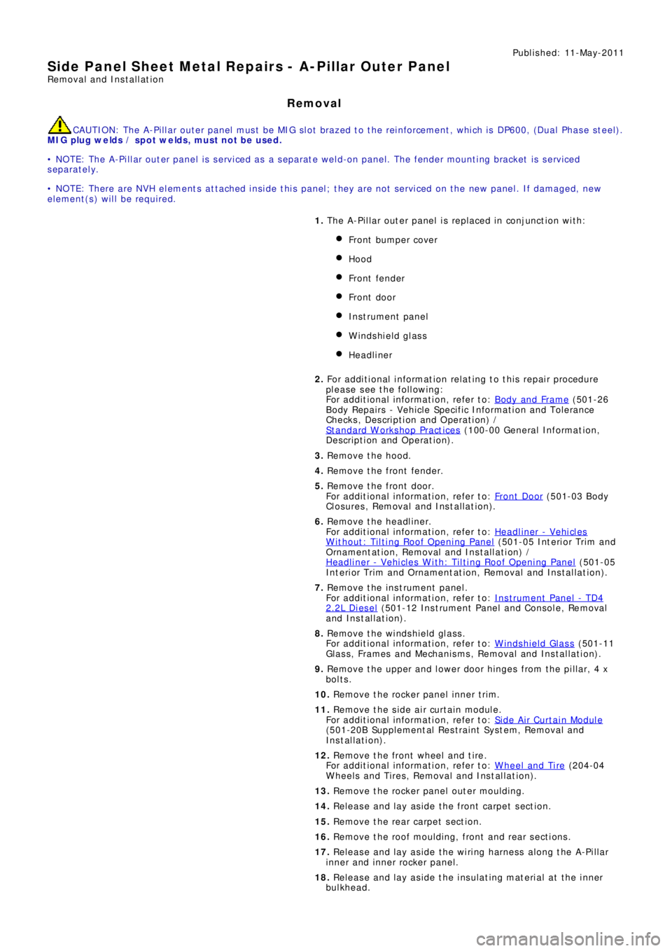
Side Panel Sheet Metal Repairs - A-Pillar Outer Panel
Removal and Installation
Removal
CAUTION: The A-Pillar outer panel must be MIG slot brazed to the reinforcement, which is DP600, (Dual Phase steel).
MIG plug we lds / spot we lds, must not be used.
• NOTE: The A-Pillar outer panel is serviced as a separate weld-on panel. The fender mounting bracket is serviced
separately.
• NOTE: There are NVH elements attached inside this panel; they are not serviced on the new panel. If damaged, new
element(s) will be required.
1. The A-Pillar out er panel is replaced in conjunct ion wit h:
Front bumper cover
Hood
Front fender
Front door
Instrument panel
Windshield glass
Headliner
2. Fo r a d d i t i o na l i nf o rma t i o n re l a t i ng t o t hi s re p a i r p ro ce d ure
please see the following:
Fo r a d d i t i o na l i nf o rma t i o n, re f e r t o : Body and Frame
(501-26
Body Repairs - Vehicle Specific Information and Tolerance
Checks, Description and Operation) /
St a nd a rd W o rks ho p P ra ct i ce s
(100-00 Ge ne ra l I nf o rma t i o n,
Description and Operation).
3. Remove the hood.
4. Remove the front fender.
5. Remove the front door.
Fo r a d d i t i o na l i nf o rma t i o n, re f e r t o : Front Door
(501-03 Body
Closures, Removal and Installation).
6. Remove the headliner.
Fo r a d d i t i o na l i nf o rma t i o n, re f e r t o : Headliner - Vehicles
Without: Tilting Roof Opening Panel (501-05 Int eri or Tri m and
Ornamentation, Removal and Installation) /
Headliner - Vehicles With: Tilting Roof Opening Panel
(501-05
Int erior Trim and Ornamentat ion, Removal and Installat ion).
7. Re move t he i ns t rume nt pa ne l .
Fo r a d d i t i o na l i nf o rma t i o n, re f e r t o : Instrument Panel - TD4
2.2L Di es el (501-12 Ins t rument Panel and Cons ole, Removal
and Installation).
8. Remove the windshield glass.
Fo r a d d i t i o na l i nf o rma t i o n, re f e r t o : Windshield Glass
(501-11
Glass, Frames and Mechanisms, Removal and Installation).
9. Remove t he upper and l ower door hi nges from t he pi l lar, 4 x
bolts.
10. Re mo ve t he ro cke r p a ne l i nne r t ri m.
11. Re mo ve t he s i d e a i r curt a i n mo d ul e .
Fo r a d d i t i o na l i nf o rma t i o n, re f e r t o : Si d e A i r Curt a i n Mo d ul e
(501-20B Suppl ement al Res t rai nt Sys t em, Removal and
Installation).
12. Remove the front wheel and tire.
Fo r a d d i t i o na l i nf o rma t i o n, re f e r t o : Wheel and Tire
(204-04
Wheels and Tires, Removal and Installation).
13. Remove the rocker panel outer moulding.
14. Release and lay aside the front carpet section.
15. Re mo ve t he re a r ca rp e t s e ct i o n.
16. Remove the roof moulding, front and rear sections.
17. Release and lay aside the wiring harness along the A-Pillar
i nne r a nd i nne r ro cke r p a ne l .
18. Release and lay aside the insulating material at the inner
bulkhead.