2006 LAND ROVER FRELANDER 2 air bleeding
[x] Cancel search: air bleedingPage 413 of 3229
1
1
1
1
1
2
3
4
1
2
3
4
1
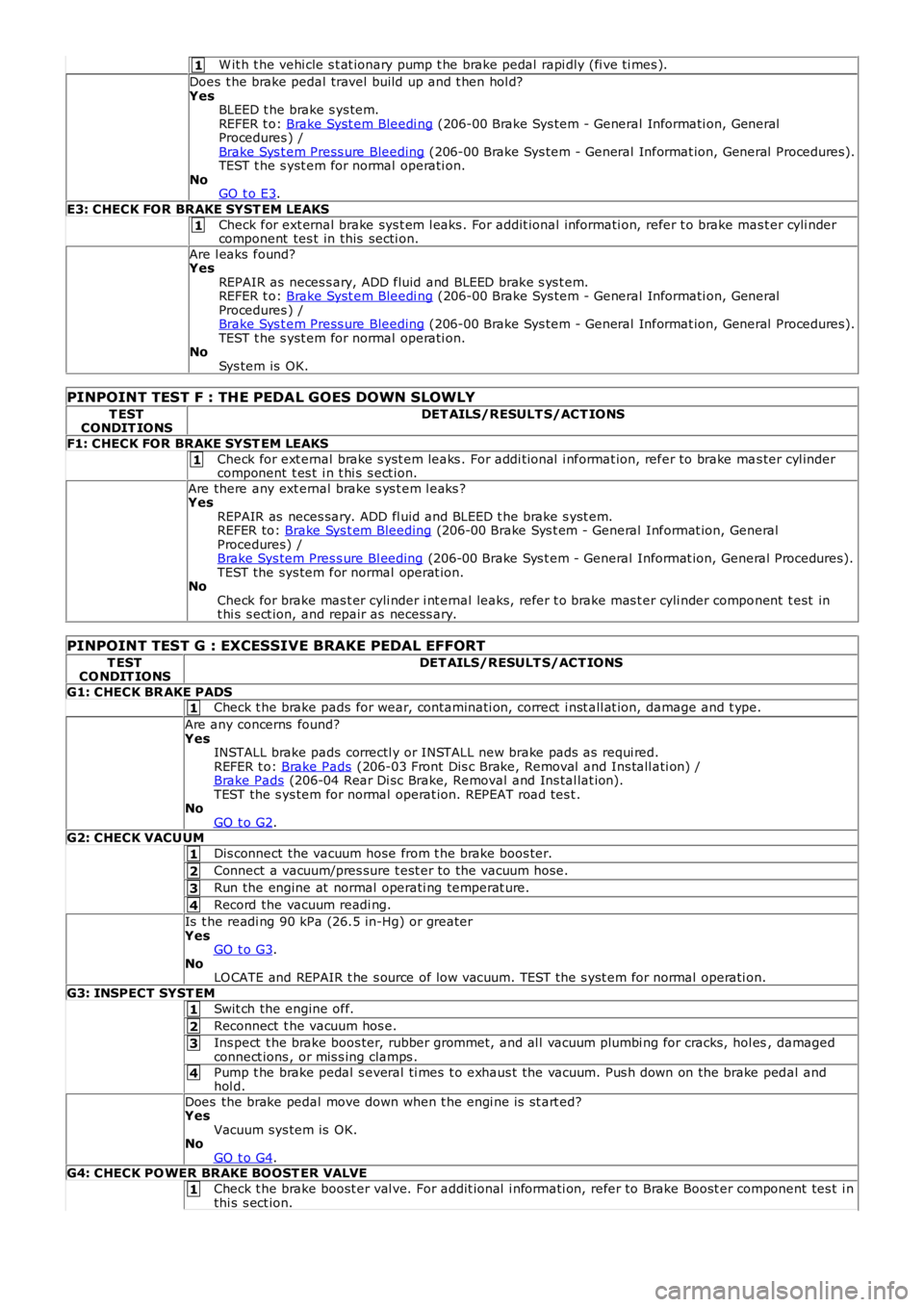
W it h t he vehi cle s t at ionary pump t he brake pedal rapi dly (fi ve ti mes ).
Does t he brake pedal travel build up and t hen hol d?YesBLEED t he brake s ys tem.REFER t o: Brake Syst em Bleedi ng (206-00 Brake Sys tem - General Informati on, GeneralProcedures ) /Brake Sys t em Press ure Bleeding (206-00 Brake Sys tem - General Informat ion, General Procedures ).TEST t he s yst em for normal operati on.NoGO t o E3.
E3: CHECK FOR BRAKE SYST EM LEAKS
Check for ext ernal brake sys t em l eaks . For addit ional informati on, refer t o brake mas t er cyli ndercomponent tes t in this secti on.
Are l eaks found?YesREPAIR as neces s ary, ADD fluid and BLEED brake s ys t em.REFER t o: Brake Syst em Bleedi ng (206-00 Brake Sys tem - General Informati on, GeneralProcedures ) /Brake Sys t em Press ure Bleeding (206-00 Brake Sys tem - General Informat ion, General Procedures ).TEST t he s yst em for normal operati on.NoSys tem is OK.
PINPOINT TEST F : THE PEDAL GOES DOWN SLOWLY
T ESTCONDIT IONSDET AILS/RESULT S/ACT IONS
F1: CHECK FOR BRAKE SYST EM LEAKS
Check for ext ernal brake s yst em leaks . For addi ti onal i nformat ion, refer to brake mas ter cyl indercomponent t es t i n t hi s s ect ion.
Are there any ext ernal brake s ys t em l eaks ?YesREPAIR as neces sary. ADD fl uid and BLEED t he brake s yst em.REFER to: Brake Sys t em Bleeding (206-00 Brake Sys t em - General Informat ion, GeneralProcedures) /Brake Sys tem Pres s ure Bl eeding (206-00 Brake Sys t em - General Informat ion, General Procedures).TEST the sys tem for normal operat ion.NoCheck for brake mas t er cyli nder i nt ernal leaks, refer t o brake mas t er cyli nder component t est int hi s s ect ion, and repair as necess ary.
PINPOINT TEST G : EXCESSIVE BRAKE PEDAL EFFORT
T ESTCO NDIT IONSDET AILS/RESULT S/ACT IONS
G1: CHECK BR AKE PADSCheck t he brake pads for wear, contaminati on, correct i nst all at ion, damage and t ype.
Are any concerns found?YesINSTALL brake pads correctl y or INSTALL new brake pads as requi red.REFER t o: Brake Pads (206-03 Front Dis c Brake, Removal and Ins tall ati on) /Brake Pads (206-04 Rear Di sc Brake, Removal and Ins tal lat ion).TEST the s ys tem for normal operat ion. REPEAT road tes t .NoGO t o G2.G2: CHECK VACUUM
Dis connect the vacuum hose from t he brake boos ter.
Connect a vacuum/pres sure t est er to the vacuum hose.
Run the engine at normal operati ng temperat ure.
Record the vacuum readi ng.
Is t he readi ng 90 kPa (26.5 in-Hg) or greaterYesGO t o G3.NoLO CATE and REPAIR t he s ource of low vacuum. TEST t he s yst em for normal operati on.
G3: INSPECT SYST EM
Swit ch the engine off.
Reconnect t he vacuum hos e.
Ins pect t he brake boos ter, rubber grommet, and al l vacuum plumbi ng for cracks, hol es, damagedconnect ions , or mis s ing clamps .
Pump t he brake pedal s everal ti mes t o exhaus t the vacuum. Pus h down on the brake pedal andhol d.
Does the brake pedal move down when t he engi ne is st art ed?YesVacuum sys tem is OK.NoGO t o G4.G4: CHECK PO WER BRAKE BOOST ER VALVE
Check t he brake boost er val ve. For addit ional i nformati on, refer to Brake Boost er component tes t i nthi s s ect ion.
Page 417 of 3229
Publi s hed: 11-May-2011
Brake System - General Information - Brake System Bleeding
General Procedures
W ARNING: If any component s upst ream of the Hydraul ic Control Uni t (HCU), including the HCU it sel f are replaced,t he brake s ys t em mus t be bl ed usi ng Land Rover approved diagnos t ic equipment . Thi s wil l ens ure that all ai r is expelledfrom the new component (s).
• NOTE: The fol lowi ng procedure covers bleedi ng t he brake s yst em i f components down st ream of the HCU have beenrepl aced. W here onl y t he primary or s econdary brake ci rcuit s have been di s turbed in i sol ati on, i t should onl y be neces s aryt o bleed t hat ci rcuit . Parti al bl eedi ng of the hydrauli c s ys t em i s only permis s ible if a brake tube or hos e has beendis connected wi th onl y mi nimal los s of fluid.
1. W ARNING: Do not work on or under a vehi cle s upported onl yby a jack. Al ways support t he vehi cl e on s afet y s tands .
Rais e and s upport t he vehi cl e.
1.
Check that t he brake fl uid l ines are s ecure and that t here are nos igns of a brake fl ui d l eak. If a brake fluid leak is det ect ed,i nves ti gat e and rect ify t he caus e of t he leak before bleeding t hebrakes .
Refer t o: Brake Syst em (206-00 Brake Sys t em - General Informat ion,Di agnos is and Tes ti ng).
2.
Pump t he brake pedal unt il t he brake vacuum ass i st ance isexhaus t ed.3.
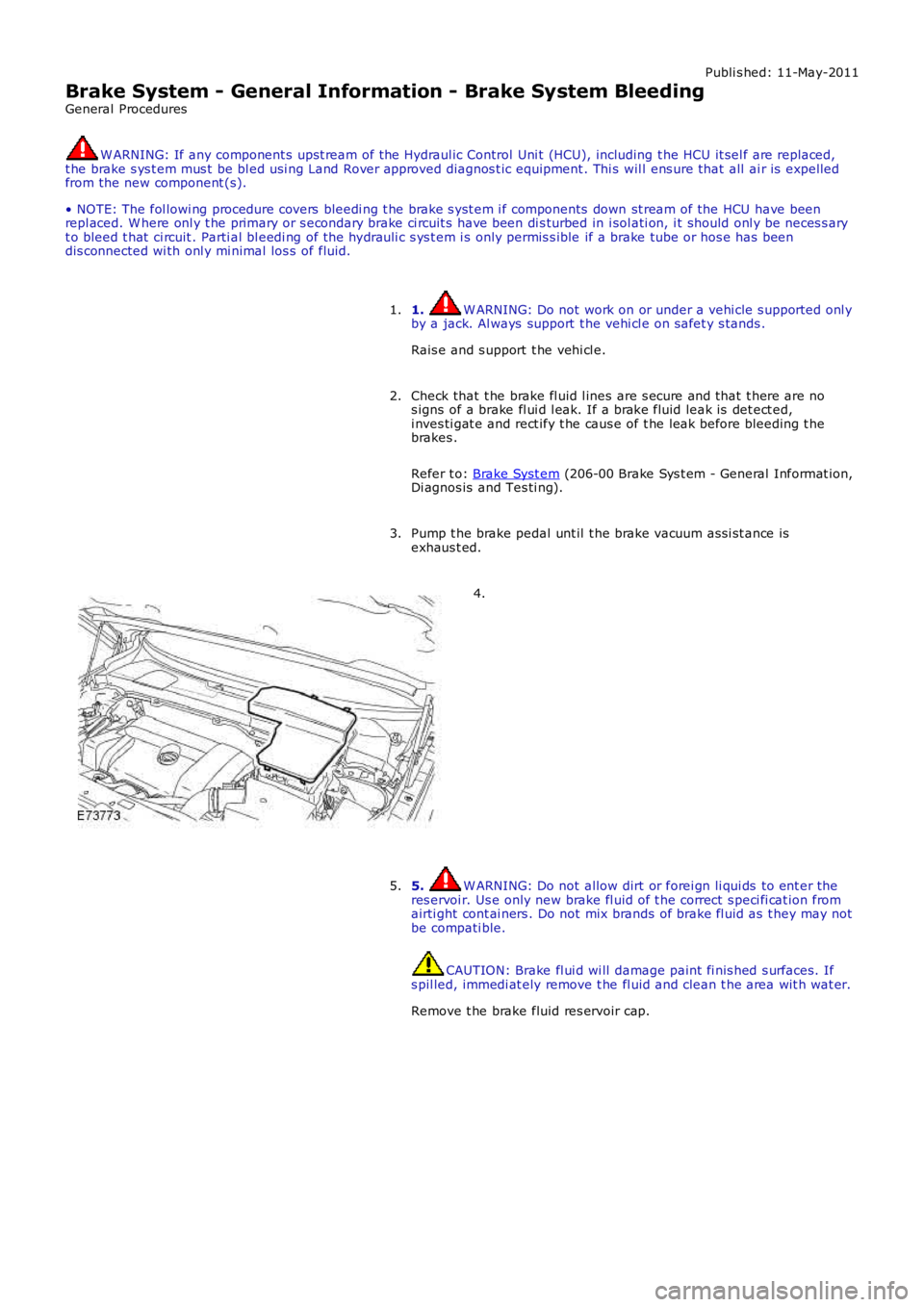
4.
5. W ARNING: Do not allow dirt or forei gn li qui ds to ent er theres ervoi r. Us e only new brake fl uid of t he correct s peci fi cat ion fromairti ght cont ai ners . Do not mix brands of brake fl uid as t hey may notbe compati ble.
CAUTION: Brake fl ui d wi ll damage paint fi nis hed s urfaces. Ifs pil led, immedi at ely remove t he fl uid and clean t he area wit h wat er.
Remove t he brake fluid res ervoir cap.
5.
Page 419 of 3229
9. CAUTION: The brake flui d res ervoir mus t remain full wi th
new, clean brake fluid at al l ti mes duri ng bleeding.
W it h ass i st ance, depres s t he brake pedal s t eadil y t hrough it s ful l
s troke and all ow it t o return t o the res t pos i ti on. Repeat the
procedure unt il brake fluid, clean and air-free fl ows int o t he bleed
jar.
9.
W hen brake fl uid, cl ean and air-free flows i nto the bl eed jar, depres s
and hold the brake pedal down.
10.
11. CAUTION: Make s ure t he bleed s crew cap is i nst all ed aft er
bleeding. This wi ll prevent corros ion t o t he bleed s crew.
W it h the brake pedal ful ly depres s ed, ti ght en t he bleed s crew.
T orque: 10 Nm 11.
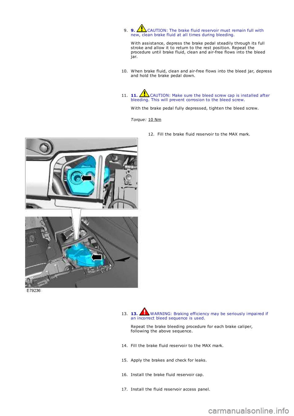
Fil l the brake fl ui d res ervoi r to t he MAX mark.
12.
13. W ARNING: Braking efficiency may be seriousl y i mpai red if
an i ncorrect bl eed s equence is us ed.
Repeat t he brake bl eedi ng procedure for each brake cali per,
fol lowi ng the above s equence.
13.
Fil l the brake fl ui d res ervoi r to t he MAX mark.
14.
Apply t he brakes and check for leaks.
15.
Inst all t he brake fluid res ervoir cap.
16.
Inst all t he fl uid reservoi r access panel.
17.
Page 551 of 3229
Refer t o:
Air Cleaner (303-12A Intake Ai r Dis tribut ion and Fil tering -
I6 3.2L Pet rol, Removal and Ins t al lat ion).
3. CAUTION: Di scard fl ui d s iphoned from t he power st eeri ng
s yst em.
Siphon t he fl uid from t he power s t eering res ervoi r.
3.
Pos it ion an abs orbent cl oth t o coll ect fluid s pi ll age.
4. 5. CAUTION: Before di s connect ing or removi ng
the component s , make s ure t he area around the joint
faces and connect ions are clean. Pl ug open
connect ions t o prevent cont aminat ion.
• NOTE: Some fluid spi llage i s inevit able duri ng t hi s
operati on.
• NOTE: Care mus t be t aken to avoi d cont aminat ion of
the acces s ory drive belt .
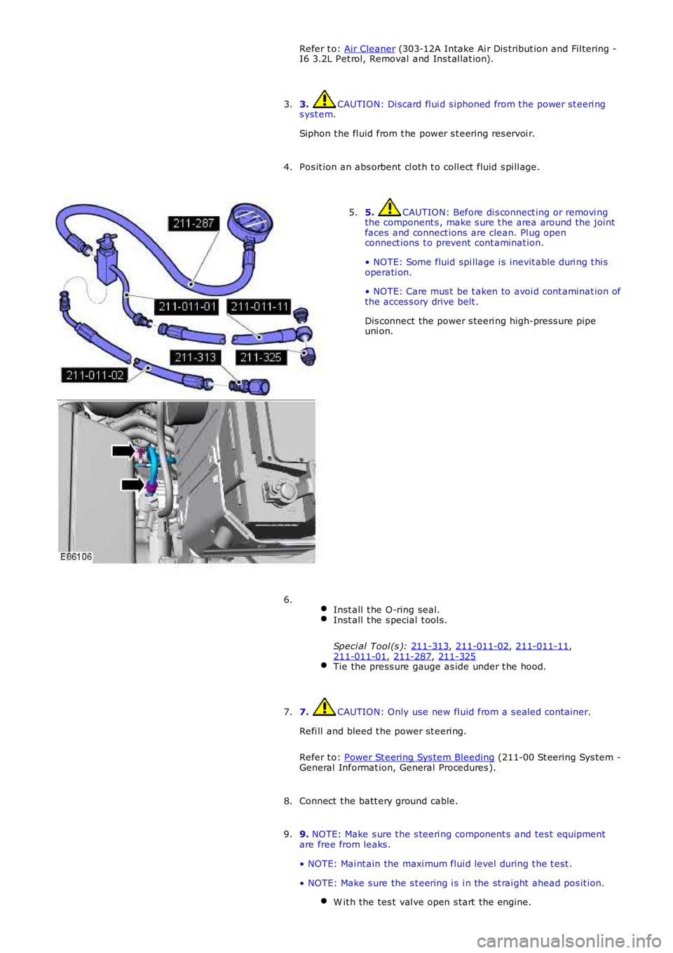
Dis connect the power s teeri ng high-press ure pipe
uni on.
5.
Inst all t he O-ring seal. Inst all t he s pecial t ool s.
Speci al Tool (s ): 211-313 ,
211-011-02 ,
211-011-11 ,
211-011-01 ,
211-287 ,
211-325 Tie the press ure gauge as ide under t he hood.6.
7. CAUTION: Only use new fl uid from a s ealed container.
Refi ll and bleed t he power st eeri ng.
Refer t o: Power St eering Sys tem Bleeding (211-00 St eering Sys tem -
General Informat ion, General Procedures ).
7.
Connect t he batt ery ground cable.
8.
9. NOTE: Make s ure t he s teeri ng component s and tes t equipment
are free from leaks .
• NOTE: Mai nt ain the maxi mum flui d level during t he t est .
• NOTE: Make s ure the s t eering i s i n the st rai ght ahead pos it ion. W it h the tes t val ve open s tart the engine. 9.
Page 556 of 3229
11.
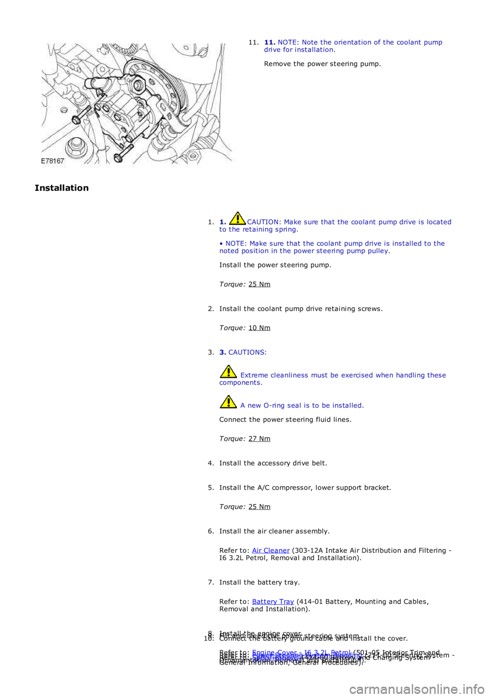
NOTE: Note t he orientat ion of t he cool ant pump
dri ve for i nst all at ion.
Remove t he power s t eering pump.
11.
Installation 1. CAUTION: Make s ure that the coolant pump drive i s located
t o t he ret aining s pri ng.
• NOTE: Make s ure that t he coolant pump drive i s ins t al led t o t he
noted pos it ion in t he power st eeri ng pump pulley.
Inst all t he power s t eering pump.
T orque: 25 Nm 1.
Inst all t he cool ant pump drive retai ni ng s crews .
T orque: 10 Nm 2.
3. CAUTIONS: Ext reme cl eanli ness must be exerci sed when handli ng t hes e
component s. A new O-ri ng s eal i s to be ins tal led.
Connect t he power s t eering flui d li nes.
T orque: 27 Nm 3.
Inst all t he acces sory dri ve bel t.
4.
Inst all t he A/C compress or, l ower support bracket.
T orque: 25 Nm 5.
Inst all t he air cleaner as s embly.
Refer t o: Air Cleaner (303-12A Intake Ai r Dis tribut ion and Fil tering -
I6 3.2L Pet rol, Removal and Ins t al lat ion).
6.
Inst all t he bat t ery t ray.
Refer t o: Bat t ery Tray (414-01 Bat tery, Mount ing and Cables ,
Removal and Ins tall ati on).
7.
Inst all t he engi ne cover.
Refer t o: Engi ne Cover - I6 3.2L Pet rol (501-05 Int eri or Trim and
Ornament ati on, Removal and Ins tal lat ion).
8.
Fil l and bl eed the power s t eering s ys tem.
Refer t o: Power St eering Sys tem Bleeding (211-00 St eering Sys tem -
General Informat ion, General Procedures ).
9.
Connect t he batt ery ground cable and ins tall t he cover.
Refer t o: Specificati ons (414-00 Bat tery and Charging Sys tem -
10.
Page 624 of 3229
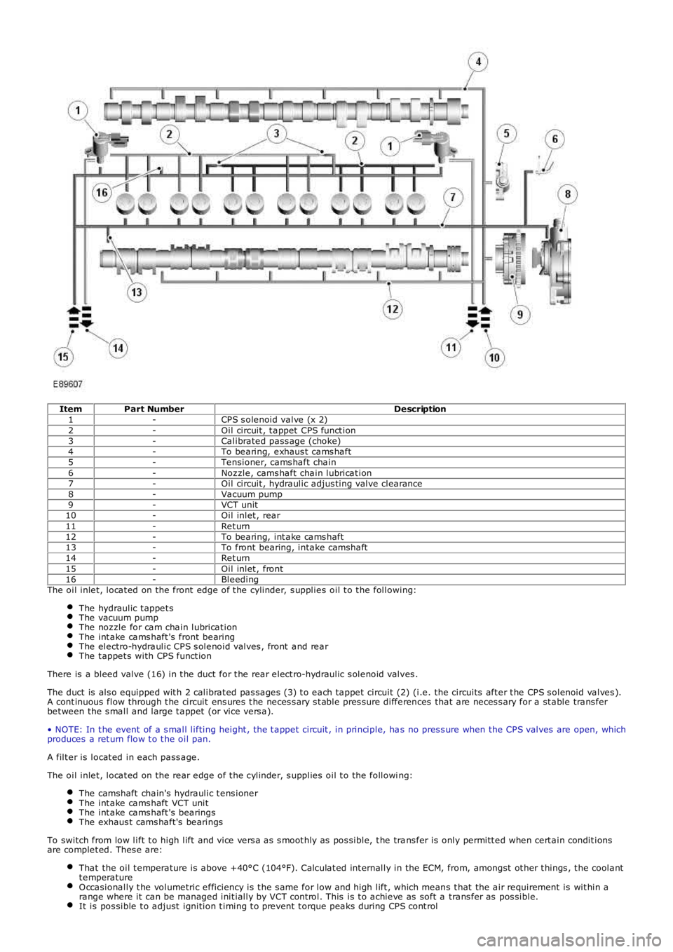
ItemPart NumberDescription1-CPS s olenoid valve (x 2)2-Oil circuit , t appet CPS funct ion3-Calibrated pass age (choke)4-To bearing, exhaus t cams haft5-Tensioner, cams haft chain6-Noz zle, cams haft chain lubricat ion7-Oil circuit , hydraulic adjus ting valve clearance8-Vacuum pump9-VCT unit10-Oil inlet , rear11-Ret urn12-To bearing, int ake cams haft13-To front bearing, intake camshaft14-Ret urn15-Oil inlet , front16-BleedingThe oil inlet , locat ed on the front edge of t he cylinder, s upplies oil t o t he following:
The hydraulic t appet sThe vacuum pumpThe noz zle for cam chain lubricat ionThe int ake cams haft 's front bearingThe electro-hydraulic CPS s olenoid valves , front and rearThe t appet s with CPS funct ion
There is a bleed valve (16) in t he duct for t he rear elect ro-hydraulic s olenoid valves .
The duct is als o equipped wit h 2 calibrat ed pas sages (3) t o each tappet circuit (2) (i.e. the circuits aft er t he CPS s olenoid valves ).A cont inuous flow through t he circuit ens ures t he neces s ary s t able pres sure differences that are neces s ary for a st able trans ferbet ween the s mall and large t appet (or vice vers a).
• NOTE: In t he event of a s mall lifting height , the t appet circuit , in principle, has no pres s ure when the CPS valves are open, whichproduces a ret urn flow t o t he oil pan.
A filt er is locat ed in each pass age.
The oil inlet , locat ed on the rear edge of t he cylinder, s upplies oil t o the following:
The camshaft chain's hydraulic t ens ionerThe int ake cams haft VCT unitThe int ake cams haft 's bearingsThe exhaus t cams haft's bearings
To switch from low lift t o high lift and vice vers a as s moot hly as pos sible, t he trans fer is only permitt ed when cert ain condit ionsare complet ed. Thes e are:
That the oil t emperature is above +40°C (104°F). Calculat ed int ernally in the ECM, from, amongst ot her t hings , t he coolantt emperatureO ccasionally t he volumetric efficiency is t he s ame for low and high lift , which means t hat the air requirement is wit hin arange where it can be managed init ially by VCT cont rol. This is t o achieve as soft a trans fer as pos sible.It is pos sible t o adjust ignition t iming t o prevent t orque peaks during CPS cont rol
Page 737 of 3229
Publi s hed: 11-May-2011
Engine - I6 3.2L Petrol - Engine
Removal
Special T ool(s)
205-857Remover, Halfs haft
General Equipment
Powert rai n Jack
• NOTE: In t hi s procedure t he engi ne and t rans mis s ion are removed t oget her.
1. W ARNING: Make sure t o s upport the vehicle wit h axles tands .
Rais e and s upport t he vehi cl e.
1.
Remove t he cover and dis connect the bat tery ground cabl e.
Refer t o: Specificati ons (414-00 Bat tery and Charging Sys tem -General Informat ion, Specificati ons).
2.
Remove t he engi ne cover.
Refer t o: Engi ne Cover - I6 3.2L Pet rol (501-05 Int eri or Trim andOrnament ati on, Removal and Ins tal lat ion).
3.
Remove t he plenum box acces s panel.
Refer t o: Plenum Chamber (412-01 Cl imat e Control, Removal andInst all at ion).
4.
Remove t he bat t ery t ray.
Refer t o: Bat t ery Tray (414-01 Bat tery, Mount ing and Cables ,Removal and Ins tall ati on).
5.
Remove t he air cleaner as s embly.
Refer t o: Air Cleaner (303-12A Intake Ai r Dis tribut ion and Fil tering -I6 3.2L Pet rol, Removal and Ins t al lat ion).
6.
Drai n t he cool ant .
Refer t o: Cool ing Sys tem Drai ni ng, Fi lli ng and Bleeding (303-03AEngine Cooli ng - I6 3.2L Petrol, General Procedures).
7.
Remove t he s tart er mot or.
Refer t o: Start er Motor (303-06A Starti ng Sys t em - I6 3.2L Pet rol ,Removal and Ins tall ati on).
8.
Remove t he cat alyti c convert ers .
Refer t o: Cat alyt ic Converter (309-00A Exhaus t Syst em - I6 3.2LPetrol, Removal and Ins tall ati on).
9.Remove t he lower engi ne s tabil izer bar.
Refer t o: Engi ne Lower Support Ins ulat or (303-01A Engine - I6 3.2LPetrol, Removal and Ins tall ati on).
10.Remove t he front subframe as s embly.
Refer t o: Front Subframe (502-00 Uni -Body, Subframe and Mount ing
11.
Page 750 of 3229
Secure t he A/C and power s t eering l ines .
24.
Inst all t he A/C compress or.
T orque: 25 Nm 25.
Inst all t he A/C compress or, upper s upport bracket.
T orque: M10 45 Nm M8
25 Nm M6
10 Nm 26.
Inst all t he A/C compress or, l ower support bracket.
T orque: 25 Nm 27.
Connect t he brake boost er vacuum hos e.
28.
Connect t he ECM elect rical connectors .
29.
Inst all t he s tart er mot or.
Refer t o: Start er Motor (303-06A Starti ng Sys t em - I6 3.2L Pet rol ,
Removal and Ins tall ati on).
30.
Remove t he front subframe as s embly.
Refer t o: Front Subframe (502-00 Uni -Body, Subframe and Mount ing
Syst em, Removal and Ins tall ati on).
31.
Inst all t he lower engi ne s tabil izer bar.
Refer t o: Engi ne Lower Support Ins ulat or (303-01B Engine - TD4 2.2L
Di es el, Removal and Ins tal lat ion).
32.
Remove t he cat alyti c convert ers .
Refer t o: Cat alyt ic Converter (309-00A Exhaus t Syst em - I6 3.2L
Petrol, Removal and Ins tall ati on).
33.
Refi ll and bleed t he cool ing s ys tem.
Refer t o: Cool ing Sys tem Drai ni ng, Fi lli ng and Bleeding (303-03A
Engine Cooli ng - I6 3.2L Petrol, General Procedures).
34.
Inst all t he air cleaner as s embly.
Refer t o: Air Cleaner (303-12B Intake Ai r Dis tribut ion and Fil tering -
TD4 2.2L Dies el, Removal and Inst all ati on).
35.
Remove t he bat t ery t ray.
Refer t o: Bat t ery Tray (414-01 Bat tery, Mount ing and Cables ,
Removal and Ins tall ati on).
36.
Remove t he plenum box acces s panel.
Refer t o: Plenum Chamber (412-01 Cl imat e Control, Removal and
Inst all at ion).
37.