2006 LAND ROVER FRELANDER 2 radio controls
[x] Cancel search: radio controlsPage 1859 of 3229
1
t o the ins tall ati on of a new module/component.
• NOTE: Generic scan t ool s may not read the codes li st ed, or may read only fi ve digit codes . Mat ch the five di git s from t hes can tool to the firs t fi ve di git s of the seven digi t code l is ted to ident ify t he faul t (t he las t t wo digi ts gi ve ext rainformat ion read by the manufact urer-approved diagnost ic s ys tem).
• NOTE: W hen performing volt age or res is t ance t est s , always use a digi tal mult imeter (DMM) accurat e t o t hree deci malplaces and wit h a current cal ibrat ion cert ificate. W hen tes ti ng res i st ance, always take the res is tance of the DMM l eads i ntoaccount.
• NOTE: Check and recti fy bas ic faul ts before beginni ng diagnos t ic rout ines i nvol vi ng pinpoint t es t s.
• NOTE: Ins pect connect ors for s igns of water ingres s , and pins for damage and/or corros ion.
• NOTE: If DTCs are recorded and, aft er performi ng the pi npoi nt tes ts , a fault is not present , an int ermi tt ent concern maybe t he caus e. Always check for loose connect ions and corroded terminals .
Informat ion and Ent ert ai nment Modul e (Low Line)
REFER to: Di agnos ti c Trouble Code (DTC) Index - DTC: Infotai nment Cont rol Modul e (ICM) - Low Li ne (100-00 GeneralInformat ion, Des cript ion and Operat ion).
Informat ion and Ent ert ai nment Modul e (High Line)
REFER to: Di agnos ti c Trouble Code (DTC) Index - DTC: Infotai nment Cont rol Modul e (ICM) - High Line (100-00 GeneralInformat ion, Des cript ion and Operat ion).
Audio Front Control Modul e (ACM)
REFER to: Di agnos ti c Trouble Code (DTC) Index - DTC: Audio Front Cont rol Modul e (ACM) (100-00 General Informati on,Des cript ion and Operat ion).
Audio Ampl ifier Modul e (AAM)
REFER to: Di agnos ti c Trouble Code (DTC) Index - DTC: Audio Ampl ifier Module (AAM) (100-00 General Informati on,Des cript ion and Operat ion).
Front Control Di s pl ay Int erface Modul e (FCDIM) (hi gh level di s pl ay front)
REFER to: Di agnos ti c Trouble Code (DTC) Index - DTC: Front Controls Di spl ay Int erface Module (FCDIM) - Front Int egratedControl Panel (100-00 General Informati on, Des cript ion and Operat ion).
Navigati on Cont rol Module (NCM)
REFER to: Di agnos ti c Trouble Code (DTC) Index - DTC: Navigati on Cont rol Module (NAV) (100-00 General Informat ion,Des cript ion and Operat ion).
Satell it e Radio Modul e (SRM)
REFER to: Di agnos ti c Trouble Code (DTC) Index - DTC: Satel lit e Di git al Audio Radi o Syst em Module (SARM) (100-00General Informat ion, Descri pti on and Operat ion).
Digi tal Audio Broadcast Modul e (DAB)
REFER to: Di agnos ti c Trouble Code (DTC) Index - DTC: Digi tal Audio Broadcas t Modul e (DABM) (100-00 GeneralInformat ion, Des cript ion and Operat ion).
High Defini ti on Tuner Module (HDR)
REFER to: Di agnos ti c Trouble Code (DTC) Index - DTC: High Defini ti on Radi o Module (HDR) (100-00 General Informat ion,Des cript ion and Operat ion).
Pinpoint Tests
• NOTE: Vis uall y ins pect for any of t he fol lowi ng condit ions and rect ify any faul t identi fied prior t o carryi ng out any tes tson t he MOST Net work.
Any s harp bends in the opt ical fibre harnes s (check for t hi s before dis turbing any module or connect or)Incorrect engagement of any opti cal connect orsIncorrect engagement of any elect rical connectorsDamage t o t he opt ical fi bre harnes s (chafing, abrasi on, ki nki ng, cuts , break, etc)Incorrect as s embly of t he opti cal network
• NOTE: Unles s ot herwis e s t at ed, ens ure vehi cl e igni ti on st atus is s et to 'ON' when carryi ng out MOST Network t est s .
PINPOINT TEST A : MOST NETWORK TESTS
T ESTCONDIT IONSDET AILS/RESULT S/ACT IONS
A1: CHECK HLDF DISPLAY
Check HLDF dis play
Is t he HLDF showi ng a flas hi ng Land Rover l ogo, or a blank s creen?YesGO to A2.NoNo ri ng break faul t has occurred. Sus pect invali d Car Configurat ion Fi le paramet er fault s , checkmodules on MOST Network for relat ed DTCs and refer t o t he rel evant DTC Index.
Page 1869 of 3229
The audi o s yst em is avail abl e in 2 vers ions , Standard and Premium.
The Standard audio s ys t em us es an int ernal ampli fier whi ch di rectl y dri ves the s ys tem s peakers and contai ns a s ingle di s cCompact Di s c (CD) pl ayer. The St andard audio s ys tem is controlled purely from the head uni t and the remote st eeri ngwheel controls . The head uni t is connect ed t o the vehicl e on t he medium speed Controll er Area Network (CAN) bus . Thisall ows the uni t to be int errogat ed for diagnost ic purpos es .
The Premi um audio sys tem compri ses t he fol lowi ng components :
Int egrat ed Audi o Module (IAM)Infotai nment Cont rol Modul e (ICM)Separate audio ampli fierRear seat audio control modul es wit h head phone socket sSurround s ound s peaker s ys t em
Control of t he Premi um audio sys tem is vi a t he ICM located in t he cent er of the i nstrument panel. Control s i gnal s from t heICM are sent t o t he res t of the audi o s ys t em on t he Media Ori ent ated Sys tem Trans port (MOST) ring. The ICM i s the ti mingmas ter for the MOST ri ng and als o host s a gat eway functi on between t he medium s peed CAN bus and the MOST ri ng.Audio s ignals are s ent on t he MOST ring from the Integrat ed Audio Modul e to the amplifier.
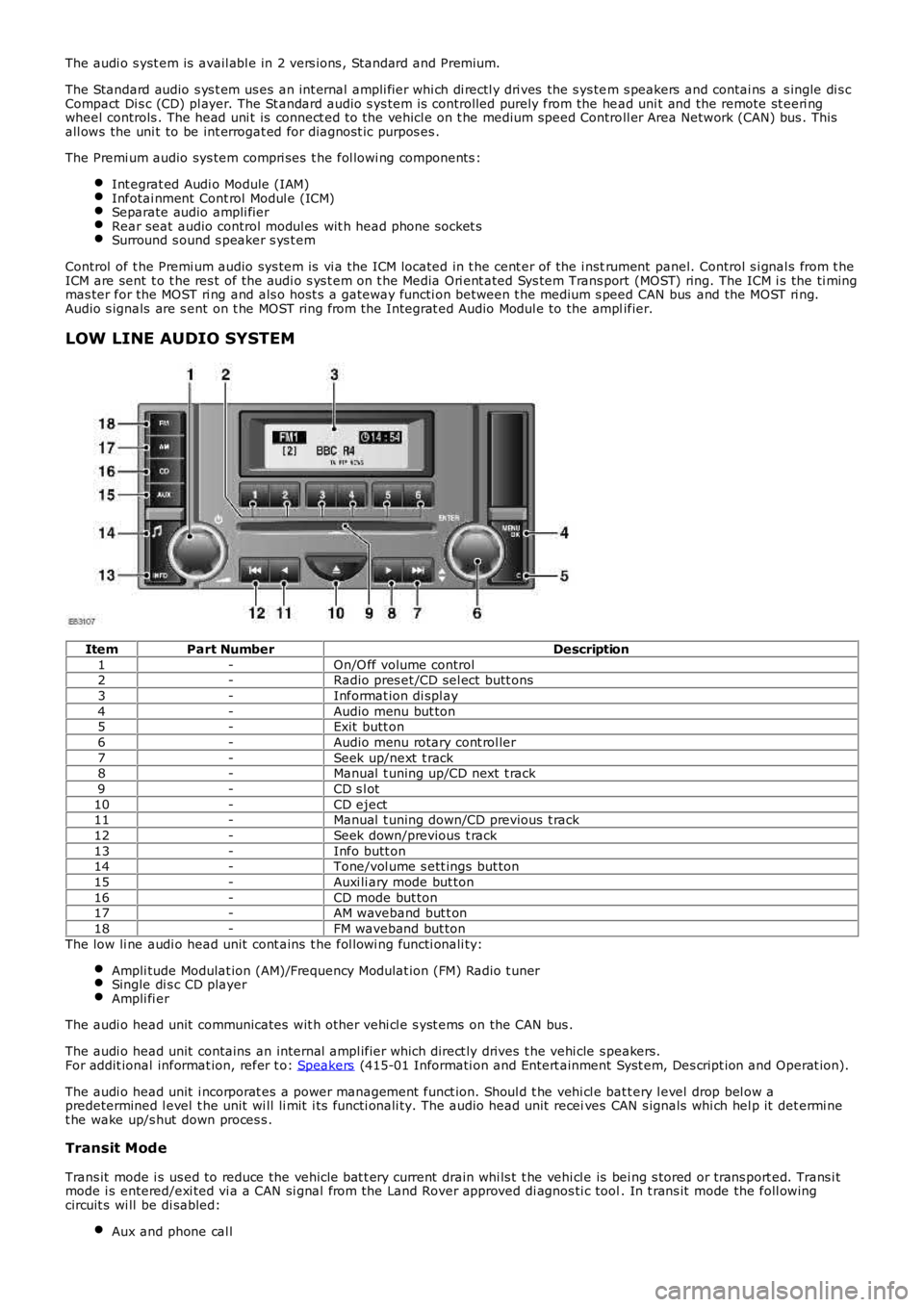
LOW LINE AUDIO SYSTEM
ItemPart NumberDescription
1-On/O ff volume control2-Radio pres et /CD sel ect butt ons
3-Informat ion di spl ay
4-Audio menu but ton5-Exit butt on
6-Audio menu rotary cont rol ler
7-Seek up/next t rack8-Manual t uning up/CD next t rack
9-CD s l ot
10-CD eject11-Manual t uning down/CD previous t rack
12-Seek down/previous t rack
13-Info butt on14-Tone/vol ume s ett ings but ton
15-Auxi li ary mode but ton
16-CD mode but ton17-AM waveband but t on
18-FM waveband but ton
The low li ne audi o head unit cont ains t he fol lowi ng functi onali ty:
Ampli tude Modulat ion (AM)/Frequency Modulat ion (FM) Radio t unerSingle di s c CD playerAmpli fi er
The audi o head unit communicates wit h other vehi cl e s yst ems on the CAN bus .
The audi o head unit contains an internal ampl ifier which direct ly drives t he vehi cle s peakers.For addit ional informat ion, refer t o: Speakers (415-01 Informati on and Entert ainment Syst em, Des cript ion and Operat ion).
The audi o head unit i ncorporat es a power management funct ion. Shoul d t he vehi cl e batt ery l evel drop bel ow apredetermined l evel t he unit wi ll li mit i ts functi onali ty. The audio head unit receives CAN s ignals whi ch hel p it det ermi net he wake up/s hut down proces s .
Transit Mode
Trans it mode i s us ed to reduce the vehicle bat t ery current drain whi ls t t he vehi cl e is bei ng s tored or trans port ed. Trans i tmode i s entered/exi ted vi a a CAN si gnal from the Land Rover approved di agnos ti c tool. In t rans it mode the foll owingcircuit s wi ll be di sabled:
Aux and phone cal l
Page 2073 of 3229
ModuleNetw orkSystemFunctionVehicle Location
Integrat ed Cont rolModuleMedi umspeed CANbus
Contains controls for the ent ert ai nment sys t em andgateway between audio s ys t em and ot her vehicles ys t ems
Int egral part of head uni t,located i n cent re cons ole
Integrat ed Head Unit(IHU)Medi umspeed CANbus
Contains controls for the ent ert ai nment sys t emInt egral part of head uni t,located i n cent re cons ole
RH rear door moduleLINControl s wi ndow and locki ng operati onMount ed i n RH rear door
LH rear door moduleLINControl s wi ndow and locki ng operati onMount ed i n LH rear doorGenerat orLINProvide l oad s ignal t o ECMLocat ed in engine compart ment .Locat ion on engine dependenton engine fit ment.
RH front s eat heatmoduleLINUs ed by ATC t o cont rol s eat heat er temperat ureUnders ide of s eat
LH front s eat heatmoduleLINUs ed by ATC t o cont rol s eat heat er temperat ureUnders ide of s eat
Air quali ty sens orLINMeasures air qualit y i n t he vehi cl e int eri orFit ted t o t he heater as sembl y
Flap act uat or modul e 1LINMoves fl aps wit hi n t he heat er ass embl y to direct airfl ow t o different parts of t he i nt eri orPart of t he heat er as s embly
Flap act uat or modul e 2LINMoves fl aps wit hi n t he heat er ass embl y to direct airfl ow t o different parts of t he i nt eri orPart of t he heat er as s embly
Flap act uat or modul e 3LINMoves fl aps wit hi n t he heat er ass embl y to direct airfl ow t o different parts of t he i nt eri orPart of t he heat er as s embly
Flap act uat or modul e 4LINMoves fl aps wit hi n t he heat er ass embl y to direct airfl ow t o different parts of t he i nt eri orPart of t he heat er as s embly
Flap act uat or modul e 5LINMoves fl aps wit hi n t he heat er ass embl y to direct airfl ow t o different parts of t he i nt eri orPart of t he heat er as s embly
Humi di ty sens orLINMeasures air qualit y i n t he vehi cl e int eri orInt egral wit h t he int eri or rearview mirror
HVAC control modul eLINControl s operat ion of t he HVAC s ys t em funct ionsInt egral wit h HVAC controlspanel i n cent re cons ole
St eering wheel moduleLINConverts analogue s ignals from s teering wheels wit ches i nto di git al mes s agesBehi nd s teering wheelclocks pri ngBatt ery backed s ounderLINActi vat ed by CJB when alarm t ri gger i s receivedMount ed i n a central pos it ionbetween t he bulkheads i n t heengi ne compartment
Electric st eeringcolumn l ockLINControl s t he locking and unlocki ng of the st eeri ngcol umnOn unders ide of s t eeringcol umn, under lower columns hroud
CJBLINControl body funct ions and power di st ributi onPass enger footwell , behi ndglovebox
Light s wit ch moduleLINControl of headlamp operat ion and l evel lingDri ver's s i de of ins trument panelVolumet ri c s ens orLINDetects movement i n vehicle i nterior and act ivatesanti -t heft alarm s ys temIn hous ing in centre ofheadl ining
Rain sens or modul eLINDetects mois t ure on t he wi nds hiel dAt top of windshi el dSt art cont rol unitLINUs ed to identi fy t he remote hands et - component oft he keyles s s t art s yst emIn ins trument panel, adjacent tothe st eeri ng col umnRF recei verLINRecei ves RF trans mi s si ons from t he TPMS s yst emand t he remot e hands etPosi ti oned adjacent t o the rearint erior l amp, behi nd theheadl ining
Headlamp l evel li ngmoduleLINControl s t he dynami c headl amp l evell ing funct ionsPass enger footwell , behi ndglovebox, int egral wit hheadl amp levell ing module
RH headlampLINProvides pos it ional i nformati on to the headlamplevell ing moduleAtt ached t o t he headl ampass embl y
LH headlampLINProvides pos it ional dat a t o t he headlamp levell ingmoduleAtt ached t o t he headl ampass embl y
Driver's window s wi tchLINControl s operat ion of t he driver's wi ndowMount ed i n dri ver's door
Driver's door moduleLINControl s wi ndow and locki ng functi onsMount ed i n dri ver's doorPas senger door moduleLINControl s wi ndow and locki ng functi onsMount ed i n pass enger door
Trans mi ss ion sel ect orl ever moduleLINSends sel ect or l ever pos it ion t o t he TCMLocat ed bel ow centre cons ole
TCMLINRecei ves s elect or l ever pos it ion i nformat ion tocont rol t rans mis s ion operat ionMount ed on t he t op of thetransmis s ion housi ngIntegrat ed Cont rolModuleMOSTContains controls for the ent ert ai nment sys t em andgateway between audio s ys t em and ot her vehicles ys t ems
Int egral part of head uni t,located i n cent re cons ole
Integrat ed Head UnitMOSTContains controls for the ent ert ai nment sys t emInt egral part of head uni t,located i n cent re cons oleDi gi tal Audio Broadcas t(DAB) recei verMOSTRecei ves di git al radi o broadcast sMount ed i n LH s ide of t heluggage compartmentBluet oot h phonemoduleMOSTControl s t he operati on of the Bl uet ooth phones ys t emMount ed i n RH s i de of theluggage compartment
Ampl ifi er/TunerMOSTProvides ampl ifi cat ion for the ent ert ainments ys t ems and recepti on of radio RF broadcas t sMount ed i n RH s i de of theluggage compartment
Navigati on comput erMOSTReads map data from a DVD t o cal cul ate and di spl ayvis ual route gui dance i nformat ion vi a t he TAD andaudi ble gui dance via the ampl ifier to the driver
Below t he IHU i n t he cent recons ole
Page 2723 of 3229

Contents
3
R
Quick start
QUICK START ................................................... 7
Filling station information
FILLING STATION INFORMATION................... 33
Introduction
SYMBOLS GLOSSARY .................................... 35
LABEL LOCATIONS ......................................... 35
HEALTH AND SAFETY ..................................... 36
DATA RECORDING.......................................... 37
DISABILITY MODIFICATIONS ......................... 37
PARTS AND ACCESSORIES ............................ 37
Keys and remote controls
USING THE KEY .............................................. 40
GENERAL INFORMATION ON RADIO
FREQUENCIES ................................................ 40
USING THE REMOTE CONTROL ..................... 41
Locks
LOCKING AND UNLOCKING ............................ 44
Alarm
ARMING THE ALARM ..................................... 45
DISARMING THE ALARM ............................... 46
Seats
SITTING IN THE CORRECT POSITION ............ 47
MANUAL SEATS ............................................. 48
ELECTRIC SEATS ............................................ 49
HEAD RESTRAINTS ........................................ 51
REAR SEATS................................................... 51
HEATED SEATS............................................... 53
Seat belts
PRINCIPLE OF OPERATION ............................ 54
SEAT BELT REMINDER ................................... 55
FASTENING THE SEAT BELTS ........................ 56
SEAT BELT HEIGHT ADJUSTMENT................. 56
USING SEAT BELTS DURI NG PREGNANCY .... 57
Supplementary restraints system
PRINCIPLE OF OPERATION ............................ 58
AIRBAG WARNING LAMP ............................... 61
DISABLING THE PASSENGER AIRBAG ........... 62
AIRBAG SERVICE INFORMATION ................... 63
Child safety
CHILD SEATS ................................................. 64
BOOSTER CUSHIONS ..................................... 66
ISOFIX ANCHOR POINTS................................ 67
CHILD SAFETY LOCKS ................................... 69
Steering wheel
ADJUSTING THE STEERING WHEEL .............. 70
AUDIO CONTROL ........................................... 70
Lighting
LIGHTING CONTROL ...................................... 72
FRONT FOG LAMPS........................................ 72
REAR FOG LAMPS.......................................... 73
ADJUSTING THE HEADLAMPS....................... 73
HEADLAMP LEVELLING ................................. 73
HAZARD WARNING FLASHERS...................... 74
ADAPTIVE FRONT LIGHTING SYSTEM (AFS) . 74
DIRECTION INDICATORS ............................... 75
INTERIOR LAMPS .......................................... 76
APPROACH LAMPS ........................................ 76
CHANGING A BULB ........................................ 77
BULB SPECIFICATION CHART ........................ 86
Wipers and washers
WINDSCREEN WIPERS .................................. 87
RAIN SENSOR ................................................ 87
WINDSCREEN WASHERS............................... 88
HEADLAMP WASHERS................................... 88
REAR WINDOW WIPER AND WASHERS ........ 89
ADJUSTING THE WINDSCREEN WASHER JETS .
89
CHECKING THE WIPER BLADES .................... 90
CHANGING THE WIPER BLADES.................... 90
Windows and mirrors
ELECTRIC WINDOWS ..................................... 93
EXTERIOR MIRRORS ..................................... 94
ELECTRIC EXTERIOR MIRRORS .................... 95
INTERIOR MIRROR ........................................ 96
Instruments
INSTRUMENT PANEL OVERVIEW .................. 97
Information displays
TRIP COMPUTER ........................................... 99
INFORMATION MESSAGES ............................ 99
Page 2725 of 3229

Contents
5
R
ENGINE COOLANT CHECK ............................ 163
BRAKE AND CLUTCH FLUID CHECK ............. 165
POWER STEERING FLUID CHECK ................ 166
WASHER FLUID CHECK ................................ 167
TECHNICAL SPECIFICATIONS ...................... 169
Vehicle battery
BATTERY WARNING SYMBOLS ................... 171
BATTERY CARE ............................................ 171
USING BOOSTER CABLES ............................ 173
CHARGING THE VE HICLE BATTERY ............. 174
CHANGING THE VE HICLE BATTERY ............. 174
Wheels and tyres
GENERAL INFORMATION ............................. 176
TYRE CARE ................................................... 177
USING WINTER TYRES................................. 183
CHANGING A ROAD WHEEL ......................... 183
TYRE REPAIR KIT ......................................... 187
USING SNOW CHAINS.................................. 192
TYRE GLOSSARY.......................................... 193
TECHNICAL SPECIFICATIONS ...................... 194
Fuses
FUSE BOX LOCATIONS ................................. 195
CHANGING A FUSE ....................................... 195
FUSE SPECIFICATION CHART....................... 196
Emergency equipment
HAZARD WARNING FLASHERS .................... 204
WARNING TRIANGLE ................................... 204
Status after a collision
DRIVING AFTER A COLLISION...................... 205
INSPECTING SAFETY SYSTEM COMPONENTS ...
206
Vehicle recovery
TOWING POINTS .......................................... 207
LASHING POINTS ......................................... 208
TRANSPORTING THE VEHICLE..................... 208
TOWING THE VEHICLE ON FOUR WHEELS .. 208
Vehicle identification
VEHICLE IDENTIFICATION PLATE................. 210
VEHICLE IDENTIFI CATION NUMBER (VIN) ... 210
VEHICLE BUILD DATE PLATE ....................... 210
Technical specifications
ENGINE SPECIFICATIONS ............................ 211
WEIGHTS...................................................... 212
DIMENSIONS................................................ 213
Type approval
Declarations of conformity ........................... 215
Audio introduction
RADIO RECEPTION....................................... 218
Audio unit overview
AUDIO UNIT OVERVIEW............................... 219
Audio unit operation
ON OR OFF CONTROL .................................. 223
VOLUME CONTROL ...................................... 223
AUDIO CONTROL ......................................... 223
WAVEBAND BUTTON ................................... 224
AUTOSTORE CONTROL ................................ 225
STATION PRESET BUTTONS ........................ 226
TRAFFIC INFORMATION CONTROL .............. 226
Audio unit menus
RADIO DATA SYSTEM (RDS) ....................... 228
REGIONAL MODE (REG) .............................. 228
ENHANCED OTHER NETWORK (RDS-EON).. 229
ALTERNATIVE FREQUENCIES ...................... 229
NEWS BROADCASTS ................................... 230
PRIORITY PROGRAMME TYPE (PTY) .......... 231
RESETTING THE AUDIO UNIT ...................... 233
Digital audio broadcasting
GENERAL INFORMATION ............................. 234
AUDIO CONTROLS ....................................... 235
DISPLAY OPTIONS ....................................... 236
CHANNEL AUTOMATIC TUNING................... 236
CHANNEL OPTIONS ..................................... 236
PRESET BUTTONS ....................................... 238
SETTINGS..................................................... 240
Compact disc player
LOADING COMPACT DISCS ......................... 245
EJECTING COMPACT DISCS ........................ 246
EJECTING MULTIPLE CO MPACT DISCS....... 246
COMPACT DISC SELECTION ........................ 246
COMPACT DISC PLAYBACK ......................... 246
Page 2749 of 3229
29
Quick start
R
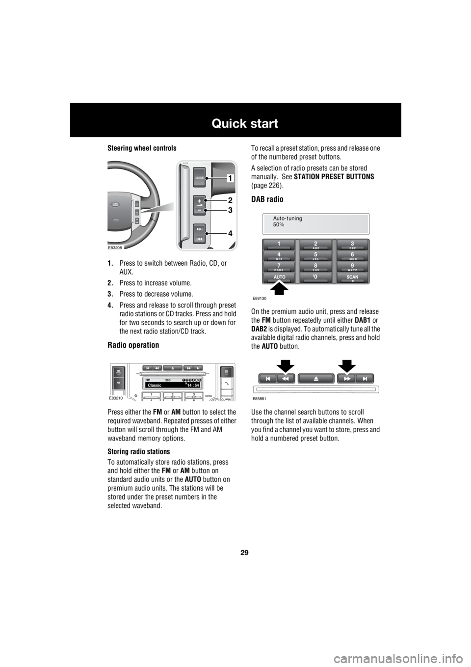
Steering wheel controls
1. Press to switch between Radio, CD, or
AUX.
2. Press to increase volume.
3. Press to decrease volume.
4. Press and release to scroll through preset
radio stations or CD tracks. Press and hold
for two seconds to search up or down for
the next radio station/CD track.
Radio operation
Press either the FM or AM button to select the
required waveband. Repeat ed presses of either
button will scroll through the FM and AM
waveband memory options.
Storing radio stations
To automatically store radio stations, press
and hold either the FM or AM button on
standard audio units or the AUTO button on
premium audio units. The stations will be
stored under the preset numbers in the
selected waveband. To recall a preset stati
on, press and release one
of the numbered preset buttons.
A selection of radio pr esets can be stored
manually. See STATION PRESET BUTTONS
(page 226).
DAB radio
On the premium audio unit, press and release
the FM button repeatedly until either DAB1 or
DAB2 is displayed. To auto matically tune all the
available digital radio channels, press and hold
the AUTO button.
Use the channel search buttons to scroll
through the list of available channels. When
you find a channel you want to store, press and
hold a numbered preset button.
1
2
3
4
E83208
FM114 : 54Classic1234 6
100.3
E83210
Auto-tuning
50%
E88130
E85661
Page 2760 of 3229
Keys and remote controls
40
L
Keys and remote controlsUSING THE KEY
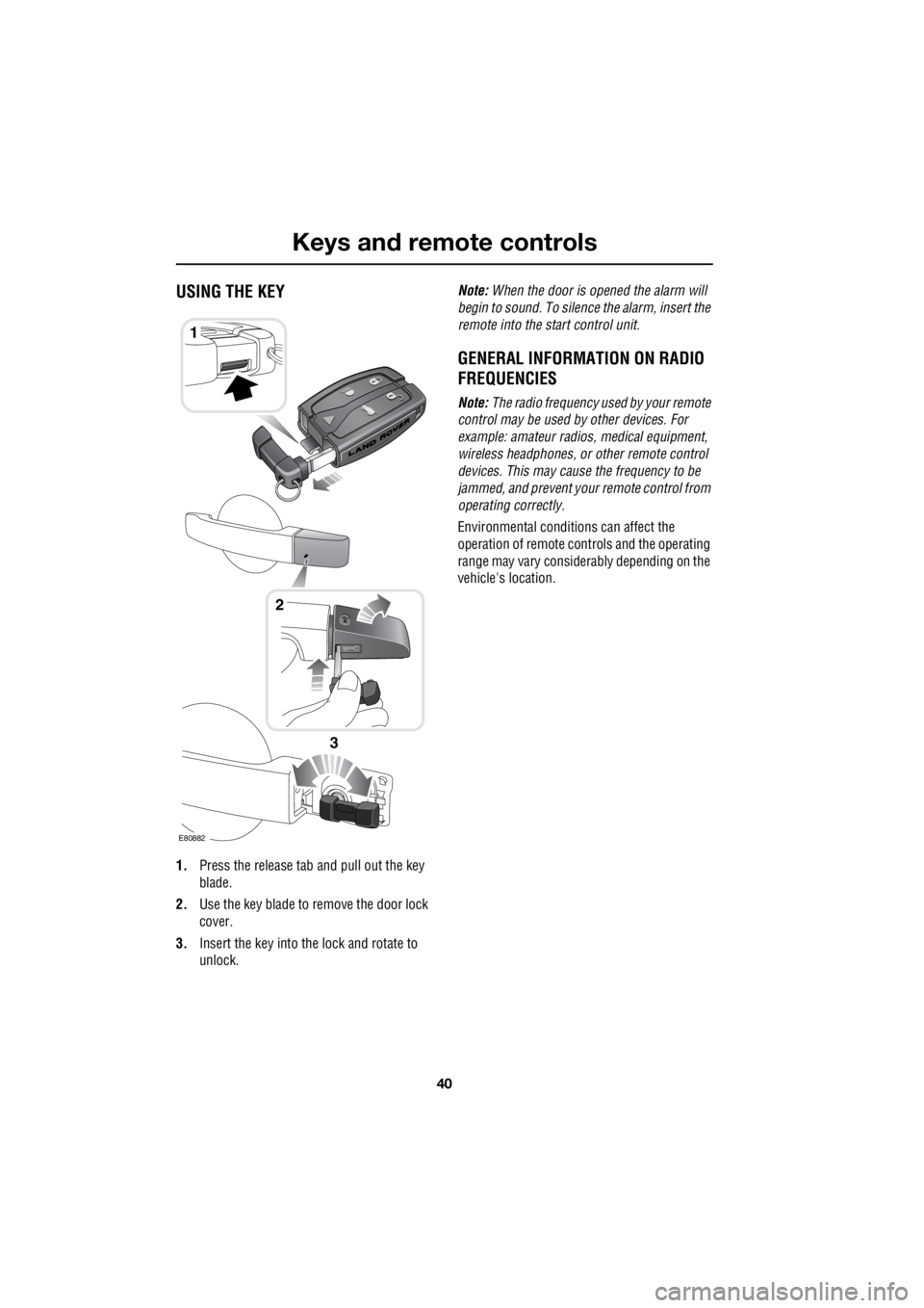
1. Press the release tab and pull out the key
blade.
2. Use the key blade to remove the door lock
cover.
3. Insert the key into the lock and rotate to
unlock. Note:
When the door is opened the alarm will
begin to sound. To silenc e the alarm, insert the
remote into the start control unit.
GENERAL INFORMATION ON RADIO
FREQUENCIES
Note: The radio frequency used by your remote
control may be used by other devices. For
example: amateur radios , medical equipment,
wireless headphones, or other remote control
devices. This may cause the frequency to be
jammed, and prevent your remote control from
operating correctly.
Environmental conditions can affect the
operation of remote cont rols and the operating
range may vary considerably depending on the
vehicle's location.
1
E80882
2
3
Page 2972 of 3229
Rear passenger controls
252
L
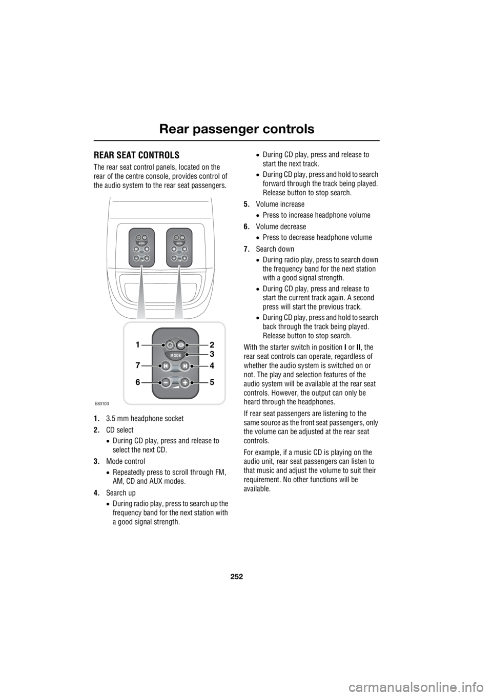
Rear passenger controlsREAR SEAT CONTROLS
The rear seat control panels, located on the
rear of the centre consol e, provides control of
the audio system to the rear seat passengers.
1. 3.5 mm headphone socket
2. CD select
• During CD play, press and release to
select the next CD.
3. Mode control
• Repeatedly press to scroll through FM,
AM, CD and AUX modes.
4. Search up
• During radio play, press to search up the
frequency band for the next station with
a good signal strength. •
During CD play, press and release to
start the next track.
• During CD play, press and hold to search
forward through the track being played.
Release button to stop search.
5. Volume increase
• Press to increase headphone volume
6. Volume decrease
• Press to decrease headphone volume
7. Search down
• During radio play, press to search down
the frequency band for the next station
with a good signal strength.
• During CD play, press and release to
start the current track again. A second
press will start the previous track.
• During CD play, press and hold to search
back through the track being played.
Release button to stop search.
With the starter switch in position I or II, the
rear seat controls can operate, regardless of
whether the audio system is switched on or
not. The play and selection features of the
audio system will be available at the rear seat
controls. However, the output can only be
heard through the headphones.
If rear seat passengers are listening to the
same source as the front seat passengers, only
the volume can be adjusted at the rear seat
controls.
For example, if a music CD is playing on the
audio unit, rear seat pa ssengers can listen to
that music and adjust the volume to suit their
requirement. No other functions will be
available.
MODE
+
MODE
+
MODE
+
1
7
6
4
3
2
5
E83103