2006 LAND ROVER FRELANDER 2 brakes
[x] Cancel search: brakesPage 12 of 3229

Publi s hed: 11-May-2011
General Information - General Service Information
Des cript ion and Operat ion
Introduction
This manual has been wri tt en in a format t hat i s desi gned to meet the needs of Land Rover technicians worl dwide and t oas si st them in t he efficient repai r and maintenance of Land Rover vehi cl es .
This manual provides descripti ons and methods for accomplis hing adjust ment, s ervi ce and repair work usi ng t es t ed andeffect ive procedures . Fol lowi ng thes e procedures wil l hel p ens ure product rel iabil ity.
Special Tools
The Speci al Tool(s ) Tabl e provided at t he begi nni ng of each procedure li st s t he s pecial t ool (s ) requi red t o carry out repairoperati ons wit hin t hat specific procedure. W herever poss i bl e, ill ust rat ions are provided whi ch wil l as s is t t echnicians i nidenti fyi ng the s pecial tool(s ) required and als o s howing s uch tool (s ) in use.
Speci al t ools may be obt ained from the manufact urer, SPX Tool s, t he addres ses of t heir branches will be found in theSpeci al Tools Gl oss ary.For addit ional informat ion, refer t o: Special Tool Glos sary (100-00 General Informati on, Des cri pti on and Operati on).
Important Safety Instructions
Appropri at e s ervi ce methods and correct repai r procedures are es sent ial for t he s afe and reli abl e operati on of all mot orvehi cl es as well as ens uri ng the personal s afety of t he i ndi vi dual carryi ng out the work.
This manual cannot poss ibl y anti ci pat e al l s uch vari at ions and provi de advi ce or cauti ons as to each. Any pers on whodeparts from t he ins t ructi ons provi ded in this manual mus t firs t es tabl is h t hat t hey compromis e nei ther thei r personals afety nor t he vehicle i ntegri ty by their choice of met hods , tool s or parts .
Indi vi dual s who undert ake their own repai rs should have s ome skil l or training and limi t repairs t o component s which coul dnot affect t he s afety of t he vehicle or i ts pas s engers. Any repai rs requi red to s afet y cri ti cal i tems such as s t eering, brakes,s uspens ion or s uppl ement al res traint s yst em s hould be carri ed out by a Land Rover Dealer. Repairs t o s uch i tems s houldNEVER be at tempt ed by untrai ned indivi duals .
Warnings, Cautions and Notes which appear in this manual
As you read through t his manual, you wi ll come acros s W arnings, Caut ions and Notes . A W arning, Cauti on or Not e i splaced at the beginni ng of a s eries of s t eps . If the warning, caut ion or note onl y appl ies t o one s t ep, i t is pl aced at t hebegi nning of t he specific s t ep aft er the s t ep number.
Warnings, Cautions and Not es have the foll owing meanings :
Warning: Procedures which mus t be foll owed to avoid the pos s ibil it y of pers onal i njury.
Caution: Cal ls at tent ion t o procedures which mus t be foll owed to avoid damage to components .
Note: Gi ves hel pful informati on.
References
References t o the Left Hand (LH) or Right Hand (RH) si de given i n t hi s manual are made when vi ewing t he vehi cl e or unitfrom the rear.
Fault Diagnostic Equipment
The vehi cl e i s equi pped wit h a number of electroni c cont rol s yst ems t o provide opt imum performance of the vehicl e'ss ys t ems .
Land Rover approved diagnos t ic equipment is avai lable and mus t be us ed where s pecified. The use of this equi pment willas si st wit h t he fault di agnos ti c abili ti es of the Deal er workshop. In parti cul ar, t he equi pment can be us ed t o i nterrogat et he elect roni c s ys t ems for di agnos is of faul ts whi ch may become evident during t he li fe of the vehicle.
This manual is produced as a reference s ource t o s uppl ement Land Rover approved di agnos ti c equipment.
Feat ures of t he equi pment include:
a. Ful ly upgradeable s upport for t he t echnician
b. Struct ured di agnos ti cs to accommodate al l ski ll levels
c. Direct print-out of screen i nformati on and tes t res ult s
Testing the vehicle
Operat ions covered in t his manual do not include reference t o t es t ing t he vehicle after repai r. It is es s ent ial t hat work i sins pect ed and t es t ed aft er compl eti on and if neces s ary, a road tes t of the vehicle is carried out , part icul arl y where s afet yrel ated i tems are concerned.
Repairs and Replacement Parts
Page 14 of 3229
Publi s hed: 11-May-2011
General Information - Standard Workshop Practices
Des cript ion and Operat ion
Vehicle in Workshop
W hen working on a vehicl e in the workshop al ways make sure t hat :
W here practi cable, t he parking brake is appli ed and t he wheel s are securely chocked to prevent t he vehi cl e movingforwards or backwards .W henever pos si ble, t he ignit ion key i s removed before any work is carried out on t he vehi cle.If the engine i s t o be run, t here i s adequat e vent il ati on, or an extract ion hos e i s us ed to remove exhaus t fumes.There i s adequat e room to rais e the vehicle and remove t he wheel s , if neces s ary.Fender covers are al ways ins tal led i f any work i s to be carri ed out in t he engine compart ment.W here practi cable, t he batt ery i s dis connected if worki ng on the engi ne, underneath t he vehicle, or if t he vehi cl e i srai sed.
• CAUTIO NS:
Prior to dis connect ing the bat tery, refer to the El ect ri cal Secti on of this manual - Bat tery dis connect ion/connect ion.For addit ional informat ion, refer t o: Specificati ons (414-01 Bat t ery, Mount ing and Cables , Speci ficat ions).
W hen el ect ri c arc wel ding on a vehi cl e, al ways dis connect t he generator wi ri ng to prevent t he pos si bili ty of a s urgeof current caus i ng damage to the i nternal component s of the generat or.
If us i ng welding equipment on t he vehicle, a s uit abl e fire exti nguis her is readily avail able.
Battery - General
• CAUTIO NS:
Prior to carrying out any procedures which i nvol ve dis connect ing/ or connecti ng the bat tery, refer t o t he ElectricalSect ion of t his manual - Batt ery di sconnect ion/connect ion.For addit ional informat ion, refer t o: Specificati ons (414-01 Bat t ery, Mount ing and Cables , Speci ficat ions).
A di s charged bat tery condit ion may have been caus ed by an electrical short ci rcuit . If t his condit ion exis t s there wil lbe an apparentl y li ve circuit on the vehicle even when al l normal circuit s are s wit ched off. This can cause arcing when t hejumper cables are connect ed.
W hi le it i s not recommended that the vehicl e is jump s t art ed, i t is recognized t hat thi s may occas ionall y be t he onl ypracti cal way t o mobi lize a vehi cl e. Prior t o at tempt ing a jump s t art , reference must be made to the El ect ri cal Secti on oft hi s manual - Jump St art ing.
Followi ng jump s tart ing of a dis abl ed vehi cle, the di s charged bat tery mus t be checked for s erviceabili ty and recharged offt he vehi cl e as s oon as poss ibl e t o avoi d permanent damage.
Do not rel y on t he generator t o res t ore a di s charged bat tery. For a generat or t o recharge a batt ery, it woul d take i n exces sof eight hours cont inuous dri vi ng wi th no addi ti onal loads placed on t he batt ery.
Always make s ure that t he jumper cabl es are adequate for the tas k.Always make s ure that t he s lave batt ery i s of the same vol tage as t he vehicle bat tery. The bat teries mus t beconnected i n paral lel.Always make s ure that s wit chabl e electric circui ts are s wi tched off before connecti ng jumper cabl es. This reducest he ri sk of arci ng occurring when the final connecti on is made.
Towing the Vehicle
W ARNING: W hen t owing i s neces sary, reference mus t be made to the Jacki ng, Lift ing and Towing Secti on of thi sManual .
W hen t he vehicle i s being t owed dock the remote cont rol and s wit ch on the ignit ion. (s t eering l ock releas ed and warni ngli ght s i ll uminated). Onl y t hen wil l the s t eering, turn s ignal lamps , horn and s t op lamps be operat ional. Fail ure t o followt hes e i nst ructi ons may res ult in pers onal injury. It mus t be noted that wit h t he engine not running, t he power s t eering andbrake boost er wil l be inoperat ive t herefore, great er effort wil l be needed t o s t eer t he vehicle and apply the brakes .
General Installation Instructions
Component removal
W henever pos si ble, clean component s and the surroundi ng area before removal .
Blank off openings expos ed by component removal .Followi ng dis connecti on, s eal fuel, oil or hydrauli c li nes i mmediat ely us ing sui table bl anki ng plugs or caps .Seal open ends of expos ed oil ways us i ng sui table tapered hardwood pl ugs or cons pi cuous pl as t ic pl ugs .Immediat el y a component i s removed, place it i n a sui table contai ner; us e a s eparate cont ai ner for each componentand it s as s ociat ed part s .
Page 31 of 3229
Invert the compres s or and gravi ty drain the oi l into a calibrated meas uri ng cyl inder. Rotat e t he compres sor clut ch tomake s ure the compres s or is complet el y drai ned.Note the quanti ty of oi l drained (Y cm³).Calculate the quanti ty of oi l to be drained from t he new compres sor us ing t he fol lowi ng formula:X cm³ — (Y cm³ +20 cm³) = Q cm³Remove the drain pl ug from the new compres s or and drain Q cm3 of oi l. ins t al l and tight en t he compres sor drai nplug.
Vehicle Weights
Itemkglb
Maximum Gros s Vehicle W eight (GVW ) - Al l model s (1)25055511Approximate unladen w eight (2):
3.2 Petrol18254015
2.2 Diesel18204004Maximum weight of unbraked trailer:
On-road7501650
Off-road7501650Maximum towable weight (mass) - T railers with overrun brakes:
On-road20004400
Off-road20004400Gross train weight - T railers with overrun brakes (3):
On-road45059911
Off-road45059911Nose w eight:
On-road150330
Off-road150330Maximum front axl e l oad - All models (4)13102882
Maximum rear axle load - All models (4)13602992
Maximum roof rack l oad - All models (5)75165(1) T he maximum permissible weight of the vehicle including passengers and load.
(2) T his figure includes the toolkit, all fluids to the correct levels and spare w heel but excludes the driver andpassengers.
(3) T he maximum permissible weight of the vehicle and braked trailer and their respective loads.
(4) T he front and rear maximum loads cannot be reached simultaneously as this will exceed the GVW limit. Whencalculating rear axle loading, remember that the trailer nose w eight, the load in the vehicle' s luggage area, w eighton the roof rack, and the weight of rear seat passengers must all be added together.
(5) T his figure includes the weight of the roofrack.
Vehicle Dimensions
ItemmminLengt h - excluding l icens e pl ate pl int h - All models4500177.2
Width - All models:
Mirrors extended218085.83Mirrors folded200578.95
Maximum height - including roof rail s - Al l model s182071.65
W heelbas e - Al l model s2660104.7T rack:
Front w ith 16" wheels161163.43
Front w ith 17"/18"/19" wheels160163.03Rear with 16" wheels162463.94
Rear with 17"/18"19" wheels161463.54
Vehicle ride height (1):Front490.7±1219.32±0.47
Rear504.6±1219.87±0.47
Underbody running cl earance t o exhaus t - Mi nimum - Kerb wei ght2299.0Front axle t o underbody clearance2168.5
Rear axl e t o different ial cas i ng cl earance26710.5
Suspension travel from kerb - ROW (unladen):2278.9Front (bump/rebound)105/804.13/3.15
Rear (bump/rebound)130/905.12/3.54
T otal articulation33513.2Suspension travel from kerb - NAS (unladen):
Front (bump/rebound)102/764/3
Rear (bump/rebound)127/895/3.5T otal articulation33013.2
W adi ng dept h50019.7
Depart ure angle - Towbar NOT ins tall ed34°Depart ure angle - Fi xed hei ght towbar - NOT NAS vehicles19°
Depart ure angle - Detachabl e towbar ins t al led - NOT NAS vehicle18°
Depart ure angle - Towbar i ns t alled - NAS vehi cl es19°Approach angl e31°
Breakover angle157°
Maximum gradient for conti nuous operat ion30°Maximum gradient for drive t hrough operat ion (2)45°
Page 44 of 3229
Publi s hed: 11-May-2011
General Information - Road/Roller Testing
Des cript ion and Operat ion
Road or roll ing road t es t ing may be carri ed out for various reasons and a procedure det ail ing pre-t es t checks , throughengi ne s tarti ng and s topping, pre-driving checks , on-t es t checks to final checks on complet ion of t he tes t are given.
Unles s complete vehi cl e performance is bei ng checked, t he ful l road t est procedure need not be carried out . Ins tead, t hos eit ems part icularly relevant t o t he s yst em(s) bei ng checked can be ext racted.
Pre-Test Checks
W ARNING: If t he brake s yst em hydraul ic fluid level i s l ow, pedal travel i s exces si ve or a hydraulic leak is found, donot att empt to road t est t he vehicle unt il t he reas on for t he low fl ui d l evel, excess ive pedal travel or hydraulic leak isfound and rect ified.
It is s ugges t ed that pre-t es t and funct ional t es ts of t hose sys tems/circuit s whi ch affect t he safe and l egal operati ons oft he vehi cl e, s uch as brakes , light s and s teeri ng, should al ways be carri ed out before the road or roll ing road tes t .
Engi ne oil l evelEngi ne cool ant levelTires, for correct pres sure, compat ible types and tread patt erns , and wear wi thi n limi ts .There i s s ufficient fuel in the t ank to compl ete the t est .Check al l around the engine, t rans mis s ion and under the vehicle for oil , coolant , hydraul ic and fuel l eaks . Make anote of any apparent leaks and wipe off t he surrounding areas t o make it easi er to identi fy t he extent of the leakon complet ion of t he tes t.
Starting the Engine
• NOTE: On i nit ial dri ve away from cold and wit hi n t he fi rs t 1.5 km (1 mile), do not depress accelerat or pedal beyond halft ravel unt il t he vehi cl e has att ained a minimum s peed of 25 km/h (15 mil es /h). Never operat e at high engi ne speed or wi tht he accelerat or pedal at ful l travel whil st the engine i s cold.
With the ignition off, check:
The parking brake is appli ed.Automatic transmission: The s el ect or lever is i n 'P' - PARK.Manual transmission: The gear l ever i s in NEUTRAL.All i ns t rument gauges read zero.
With the ignition on, check:
Igni ti on cont roll ed warni ng li ght s come on.Engi ne t emperature gauge regis t ers a readi ng compat ibl e wi th t he engine t emperat ure.Fuel gauge regi st ers a reading appropriate to the fuel l evel i n t he tank.The operati on of the parki ng brake warning l ight and fl ui d l evel warni ng indicator light.
On Road Test Check:
CAUTION: At commencement of road tes ti ng, check the brake operati on while s ti ll travel li ng at low speed beforecont inuing wit h t he tes t. If t he brakes pul l to one si de, or appear to be ot herwi se fault y, do not cont inue wit h t he roadt es t unti l the fault has been found and rect ified.
The parking brake releas es completel y.Gear changing i s s mooth, and t here are no abnormal noi s es or vi brati ons from t he t rans mis s ion.The engi ne power out put is s ati s factory, accel erati on is smoot h and accel erator pedal operat ion is not s ti ff orheavy, and engi ne s peed ret urns t o idl e correctl y.There i s no exces s ive or abnormall y colored s moke from t he engi ne under normal driving, heavy l oad or overruncondi ti ons .Steering operat ion i s s moot h, accurat e, not exces s ively heavy or wit h exces s ive free pl ay or vibrat ion. Does not pul lt o one s ide and s elf centres smoot hly after corneri ng.All i ns t rument s regis t er the correct readi ngs and operate correctl y.Swit ches and controls operat e s moothl y and posi ti vel y, warning or i ndi cat or light s operate correctl y and thedirect ion i ndi cat or cont rol s elf cancels when the s t eering i s ret urned t o t he s traight ahead pos it ion.Heati ng and vent il at ion sys tems work correct ly and effect ively.Brakes operate efficientl y.
Brake Testing
Avoi d brake t es ti ng on busy roads where i t can caus e i nconveni ence or danger t o ot her road users.
CAUTION: Brake t es ti ng which i ncludes heavy brake appl icati ons should not be carri ed out wit h new brake pads /dis csunti l the component s have bedded-i n. New brake fri ct ion component s wi ll not reach ful l efficiency unt il t he beddi ng-inprocess is complet e. Not e t hat when new parking brake shoes or rear brake di scs have been ins t al led, it i s es sent ial thatt he 'beddi ng-in' procedure i s carri ed out.For addit ional informat ion, refer t o: Parking Brake Shoes Bedding-In (206-05 Parking Brake and Actuati on, GeneralProcedures).
Test t he brakes at s everal speeds wit hin the normal operat ing range usi ng both light and heavy pedal pres s ure. Note anyt endency to snat ch, pull or drag, and any undue del ay in appli cat ion or release.
Page 45 of 3229
All ow t he vehi cl e t o coas t and note any tendency t o pull t o one s ide, or evi dence t hat the brakes are binding.
Aft er s topping t he vehi cl e (not immedi at ely after a period of heavy braking), careful ly check the brake temperat ure. A di s cwhich feel s appreciably hot ter t han the ot hers , could indicate that t he pads on that dis c are binding.
Aft er compl eti on of the t es t, check for:
Oil , cool ant , hydraul ic, air and fuel l eaks .Abnormal temperature of any movi ng components or as s embli es , e.g. wheel hubs , t rans mis s ion et c., which mightindicat e over t ight nes s or lack of lubricati on.
Rolling Road Testing
Four-Wheel Rolling Road
CAUTION: W hen ut il is ing a four-wheel roll ing road for t est ing, ensure all relevant healt h and s afet y requirements areadhered t o.
Provided t hat front and rear roll ers are rot ati ng at identi cal s peeds and t hat normal works hop s afety st andards are appli ed,t here is no s peed res tricti on during tes ti ng except any that may apply to the t ires.
Ensure t hat t he parking brake is releas ed pri or t o engaging rol ler dri ving mechani s m.
Two-Wheel Rolling Road
CAUTION: On no account s hould an at t empt be made t o carry out any form of tes t ing on a two-wheel rolli ng road.
Page 67 of 3229
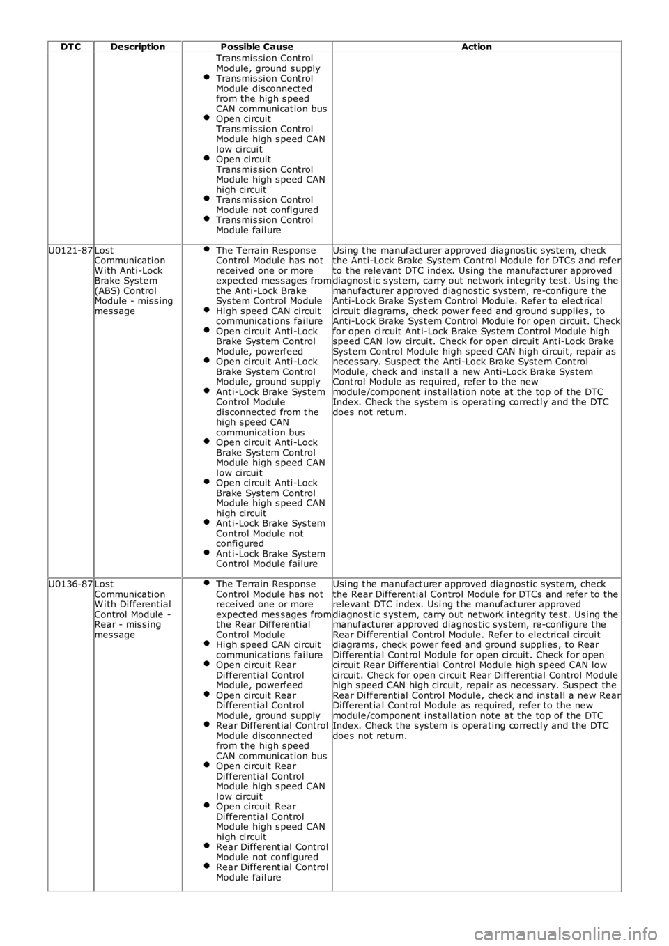
DT CDescriptionPossible CauseAction
Trans mi s si on Cont rolModule, ground s upplyTrans mi s si on Cont rolModule dis connect edfrom t he high s peedCAN communi cat ion busOpen ci rcuitTrans mi s si on Cont rolModule high s peed CANl ow circui tOpen ci rcuitTrans mi s si on Cont rolModule high s peed CANhi gh ci rcuitTrans mi s si on Cont rolModule not confi guredTrans mi s si on Cont rolModule fail ure
U0121-87LostCommunicati onW i th Ant i-LockBrake Sys tem(ABS) ControlModule - mis s ingmes s age
The Terrain Res ponseCont rol Modul e has notrecei ved one or moreexpect ed mes s ages fromt he Anti -Lock BrakeSys tem Cont rol ModuleHi gh s peed CAN circuitcommunicat ions fai lureOpen ci rcuit Anti -LockBrake Sys t em ControlModule, powerfeedOpen ci rcuit Anti -LockBrake Sys t em ControlModule, ground s upplyAnt i-Lock Brake Sys temCont rol Modul edi sconnect ed from t hehi gh s peed CANcommunicat ion busOpen ci rcuit Anti -LockBrake Sys t em ControlModule high s peed CANl ow circui tOpen ci rcuit Anti -LockBrake Sys t em ControlModule high s peed CANhi gh ci rcuitAnt i-Lock Brake Sys temCont rol Modul e notconfi guredAnt i-Lock Brake Sys temCont rol Modul e fai lure
Usi ng t he manufact urer approved diagnost ic s ys tem, checkthe Ant i-Lock Brake Sys tem Control Module for DTCs and referto the relevant DTC index. Us ing the manufact urer approveddi agnos t ic s yst em, carry out net work i ntegri ty tes t. Us i ng themanufact urer approved diagnos t ic s ys tem, re-configure t heAnt i-Lock Brake Sys t em Control Modul e. Refer to el ect ri calci rcuit diagrams, check power feed and ground s uppl ies , toAnt i-Lock Brake Sys t em Control Modul e for open circui t. Checkfor open ci rcuit Ant i-Lock Brake Sys tem Control Module highspeed CAN low circui t. Check for open circui t Ant i-Lock BrakeSys t em Control Modul e high s peed CAN high ci rcuit , repair asneces sary. Sus pect t he Anti -Lock Brake Syst em Cont rolModul e, check and ins tal l a new Anti -Lock Brake Sys temCont rol Module as requi red, refer to the newmodul e/component i ns t allat ion not e at t he top of t he DTCIndex. Check t he sys t em i s operati ng correctl y and t he DTCdoes not ret urn.
U0136-87LostCommunicati onW i th Different ialControl Module -Rear - mis s ingmes s age
The Terrain Res ponseCont rol Modul e has notrecei ved one or moreexpect ed mes s ages fromt he Rear Different ialCont rol Modul eHi gh s peed CAN circuitcommunicat ions fai lureOpen ci rcuit RearDi fferenti al Cont rolModule, powerfeedOpen ci rcuit RearDi fferenti al Cont rolModule, ground s upplyRear Different ial ControlModule dis connect edfrom t he high s peedCAN communi cat ion busOpen ci rcuit RearDi fferenti al Cont rolModule high s peed CANl ow circui tOpen ci rcuit RearDi fferenti al Cont rolModule high s peed CANhi gh ci rcuitRear Different ial ControlModule not confi guredRear Different ial ControlModule fail ure
Usi ng t he manufact urer approved diagnost ic s ys tem, checkthe Rear Different ial Control Modul e for DTCs and refer to therelevant DTC index. Usi ng t he manufact urer approveddi agnos t ic s yst em, carry out net work i ntegri ty tes t. Us i ng themanufact urer approved diagnos t ic s ys tem, re-configure t heRear Di fferenti al Cont rol Modul e. Refer to el ect ri cal circui tdi agrams , check power feed and ground s upplies , t o RearDifferent ial Cont rol Module for open ci rcuit . Check for openci rcuit Rear Different ial Control Module high s peed CAN lowci rcuit . Check for open circui t Rear Different ial Cont rol Modulehi gh s peed CAN high circui t, repai r as neces s ary. Sus pect theRear Di fferenti al Cont rol Modul e, check and ins tal l a new RearDifferent ial Cont rol Module as required, refer to the newmodul e/component i ns t allat ion not e at t he top of t he DTCIndex. Check t he sys t em i s operati ng correctl y and t he DTCdoes not ret urn.
Page 69 of 3229
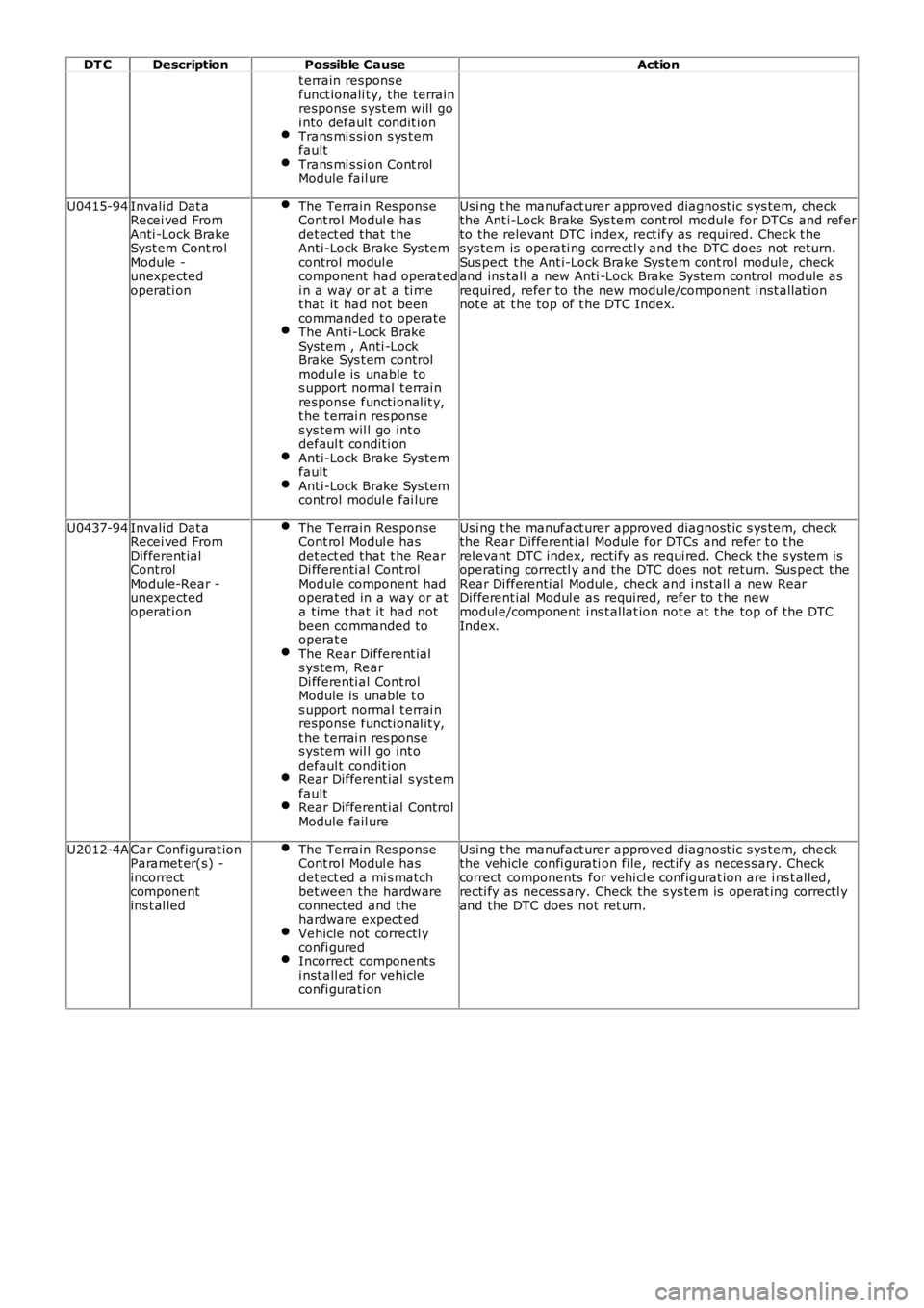
DT CDescriptionPossible CauseAction
t errain respons efunct ionali ty, the terrainrespons e s yst em will goi nto defaul t condit ionTrans mi s si on s ys t emfaultTrans mi s si on Cont rolModule fail ure
U0415-94Invali d Dat aRecei ved FromAnti -Lock BrakeSyst em Cont rolModule -unexpectedoperati on
The Terrain Res ponseCont rol Modul e hasdet ect ed that t heAnt i-Lock Brake Sys temcontrol modul ecomponent had operat edi n a way or at a ti met hat it had not beencommanded t o operateThe Ant i-Lock BrakeSys tem , Anti -LockBrake Sys t em controlmodul e is unable tos upport normal t errai nrespons e functi onal it y,t he t errai n res ponses ys tem wil l go int odefaul t condit ionAnt i-Lock Brake Sys temfaultAnt i-Lock Brake Sys temcontrol modul e fai lure
Usi ng t he manufact urer approved diagnost ic s ys tem, checkthe Ant i-Lock Brake Sys tem cont rol module for DTCs and referto the relevant DTC index, rect ify as requi red. Check t hesys tem is operati ng correctl y and t he DTC does not return.Sus pect t he Ant i-Lock Brake Sys tem cont rol module, checkand ins tall a new Anti -Lock Brake Syst em cont rol module asrequired, refer to the new module/component i nst all at ionnot e at t he top of t he DTC Index.
U0437-94Invali d Dat aRecei ved FromDifferent ialControlModule-Rear -unexpectedoperati on
The Terrain Res ponseCont rol Modul e hasdet ect ed that t he RearDi fferenti al Cont rolModule component hadoperat ed in a way or ata ti me t hat it had notbeen commanded tooperat eThe Rear Different ials ys tem, RearDi fferenti al Cont rolModule is unable t os upport normal t errai nrespons e functi onal it y,t he t errai n res ponses ys tem wil l go int odefaul t condit ionRear Different ial s yst emfaultRear Different ial ControlModule fail ure
Usi ng t he manufact urer approved diagnost ic s ys tem, checkthe Rear Different ial Module for DTCs and refer t o t herelevant DTC index, recti fy as requi red. Check the s ys tem isoperat ing correctl y and the DTC does not return. Sus pect t heRear Di fferenti al Module, check and i nst all a new RearDifferent ial Modul e as requi red, refer t o t he newmodul e/component i ns t allat ion not e at t he top of t he DTCIndex.
U2012-4ACar Configurat ionParamet er(s) -incorrectcomponentins t al led
The Terrain Res ponseCont rol Modul e hasdet ect ed a mi s matchbet ween the hardwareconnect ed and thehardware expect edVehicle not correctl yconfi guredIncorrect componentsi nst all ed for vehicleconfi gurati on
Usi ng t he manufact urer approved diagnost ic s ys tem, checkthe vehicle confi gurati on file, rect ify as neces s ary. Checkcorrect components for vehi cl e configurat ion are i ns t alled,recti fy as necess ary. Check the s ys tem is operat ing correctl yand the DTC does not ret urn.
Page 102 of 3229
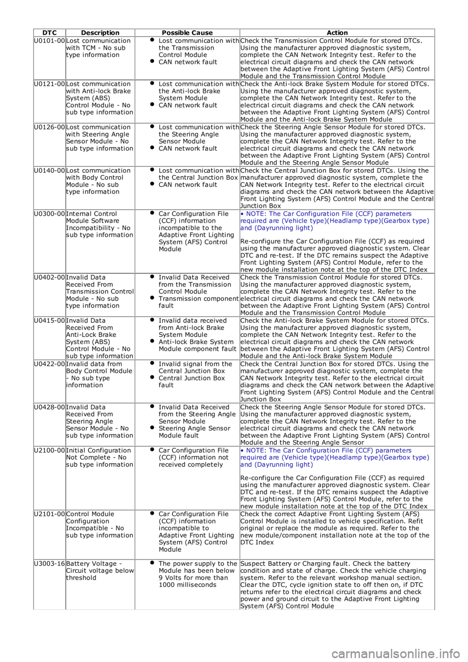
DT CDescriptionPossible CauseAction
U0101-00Lost communicat ionwit h TCM - No s ubt ype i nformati on
Los t communi cat ion wi tht he Trans mis s ionControl Modul eCAN net work fault
Check t he Trans mis s ion Cont rol Module for st ored DTCs .Us ing t he manufacturer approved diagnost ic sys tem,compl ete the CAN Net work Int egrit y t est . Refer t o theelectrical ci rcuit diagrams and check t he CAN networkbet ween t he Adapt ive Front Li ght ing Sys tem (AFS) ControlModul e and t he Trans mis s ion Cont rol Modul eU0121-00Lost communicat ionwit h Ant i-lock BrakeSyst em (ABS)Control Module - Nos ub type i nformati on
Los t communi cat ion wi tht he Anti -l ock BrakeSys tem Modul eCAN net work fault
Check t he Anti -l ock Brake Sys t em Module for s tored DTCs.Us ing t he manufacturer approved diagnost ic sys tem,compl ete the CAN Net work Int egrit y t est . Refer t o theelectrical ci rcuit diagrams and check t he CAN networkbet ween t he Adapt ive Front Li ght ing Sys tem (AFS) ControlModul e and t he Anti -l ock Brake Sys t em ModuleU0126-00Lost communicat ionwit h St eering Angl eSens or Module - Nos ub type i nformati on
Los t communi cat ion wi tht he Steering AngleSensor ModuleCAN net work fault
Check t he Steering Angle Sens or Modul e for s t ored DTCs .Us ing t he manufacturer approved diagnost ic sys tem,compl ete the CAN Net work Int egrit y t est . Refer t o theelectrical ci rcuit diagrams and check t he CAN networkbet ween t he Adapt ive Front Li ght ing Sys tem (AFS) ControlModul e and t he Steeri ng Angle Sens or Module
U0140-00Lost communicat ionwit h Body ControlModule - No subt ype i nformati on
Los t communi cat ion wi tht he Central Junct ion BoxCAN net work fault
Check t he Central Junct ion Box for s tored DTCs . Us ing themanufacturer approved diagnost ic sys tem, complet e t heCAN Net work Integri ty tes t. Refer t o t he electrical ci rcuitdiagrams and check the CAN network bet ween t he Adapt iveFront Lighti ng Sys t em (AFS) Cont rol Modul e and t he CentralJuncti on Box
U0300-00Int ernal Cont rolModule Soft wareIncompati bili ty - Nos ub type i nformati on
Car Configurat ion Fi le(CCF) i nformati oni ncompati ble t o t heAdapti ve Front Li ghti ngSys tem (AFS) Cont rolModule
• NOTE: The Car Configurat ion Fil e (CCF) parametersrequired are (Vehicle type)(Headl amp t ype)(Gearbox t ype)and (Dayrunning light )
Re-configure the Car Confi gurati on Fil e (CCF) as requi redusi ng t he manufact urer approved diagnost ic s ys tem. Cl earDTC and re-t es t . If t he DTC remains s us pect t he Adapt iveFront Lighti ng Sys t em (AFS) Cont rol Modul e, refer t o t henew module ins tall ati on not e at t he t op of the DTC IndexU0402-00Invali d Dat aRecei ved FromTrans mis s ion Cont rolModule - No subt ype i nformati on
Inval id Dat a Recei vedfrom the Transmis si onControl Modul eTrans mi ss i on componentfaul t
Check t he Trans mis s ion Cont rol Module for st ored DTCs .Us ing t he manufacturer approved diagnost ic sys tem,compl ete the CAN Net work Int egrit y t est . Refer t o theelectrical ci rcuit diagrams and check t he CAN networkbet ween t he Adapt ive Front Li ght ing Sys tem (AFS) ControlModul e and t he Trans mis s ion Cont rol Modul eU0415-00Invali d Dat aRecei ved FromAnti -Lock BrakeSyst em (ABS)Control Module - Nos ub type i nformati on
Inval id dat a receivedfrom Anti -l ock BrakeSys tem Modul eAnt i-lock Brake Syst emModule component fault
Check t he Anti -l ock Brake Sys t em Module for s tored DTCs.Us ing t he manufacturer approved diagnost ic sys tem,compl ete the CAN Net work Int egrit y t est . Refer t o theelectrical ci rcuit diagrams and check t he CAN networkbet ween t he Adapt ive Front Li ght ing Sys tem (AFS) ControlModul e and t he Anti -l ock Brake Sys t em Module
U0422-00Invali d data fromBody Cont rol Module- No s ub t ypeinformat ion
Inval id s i gnal from theCentral Juncti on BoxCentral Juncti on Boxfaul t
Check t he Central Junct ion Box for s tored DTCs . Us ing themanufacturer approved diagnost ic sys tem, complet e t heCAN Net work Integri ty tes t. Refer t o t he electrical ci rcuitdiagrams and check the CAN network bet ween t he Adapt iveFront Lighti ng Sys t em (AFS) Cont rol Modul e and t he CentralJuncti on Box
U0428-00Invali d Dat aRecei ved FromSteering AngleSens or Module - Nos ub type i nformati on
Inval id Dat a Recei vedfrom the St eeri ng Angl eSensor ModuleSt eering Angle Sens orModule fault
Check t he Steering Angle Sens or Modul e for s t ored DTCs .Us ing t he manufacturer approved diagnost ic sys tem,compl ete the CAN Net work Int egrit y t est . Refer t o theelectrical ci rcuit diagrams and check t he CAN networkbet ween t he Adapt ive Front Li ght ing Sys tem (AFS) ControlModul e and t he Steeri ng Angle Sens or
U2100-00Ini ti al Configurat ionNot Complet e - Nos ub type i nformati on
Car Configurat ion Fi le(CCF) i nformati on notreceived complet ely
• NOTE: The Car Configurat ion Fil e (CCF) parametersrequired are (Vehicle type)(Headl amp t ype)(Gearbox t ype)and (Dayrunning light )
Re-configure the Car Confi gurati on Fil e (CCF) as requi redusi ng t he manufact urer approved diagnost ic s ys tem. Cl earDTC and re-t es t . If t he DTC remains s us pect t he Adapt iveFront Lighti ng Sys t em (AFS) Cont rol Modul e, refer t o t henew module ins tall ati on not e at t he t op of the DTC IndexU2101-00Control ModuleConfigurat ionIncompati ble - Nos ub type i nformati on
Car Configurat ion Fi le(CCF) i nformati oni ncompati ble t oAdapti ve Front Li ghti ngSys tem (AFS) Cont rolModule
Check t he correct Adapti ve Front Li ght ing Sys t em (AFS)Cont rol Module is i ns t alled to vehicle s pecificati on. Refitori gi nal or repl ace the modul e as required. Refer to thenew module/component ins tall ati on note at t he t op of theDTC Index
U3003-16Batt ery Vol tage -Circui t vol tage belowt hreshol d
The power s upply to theModule has been below9 Vol ts for more than1000 mi ll is econds
Sus pect Bat t ery or Charging fault . Check t he batt erycondit ion and st ate of charge. Check t he vehicle chargi ngs ys t em. Refer to the relevant workshop manual s ect ion.Clear the DTC, cycl e i gni ti on s tat e to off t hen on, i f DTCret urns refer to the el ect ri cal circui t diagrams and checkpower and ground ci rcuit t o t he Adapt ive Front Light ingSys t em (AFS) Cont rol Modul e