2006 LAND ROVER FRELANDER 2 warning lights
[x] Cancel search: warning lightsPage 1791 of 3229
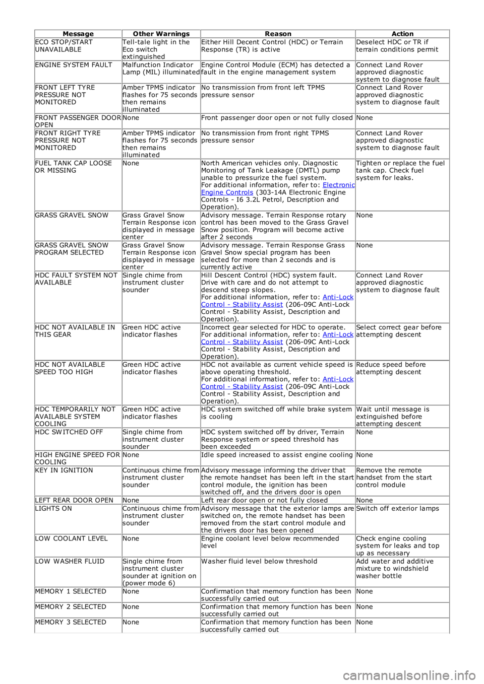
MessageO ther WarningsReasonAction
ECO STOP/STARTUNAVAILABLETel l-tal e li ght in t heEco swi tchext inguis hed
Eit her Hi ll Decent Control (HDC) or TerrainRespons e (TR) i s act iveDes elect HDC or TR i fterrain condit ions permi t
ENGINE SY STEM FAULTMalfunct ion Indi cat orLamp (MIL) il lumi nat edEngi ne Cont rol Module (ECM) has detected afault i n t he engi ne management s ys temConnect Land Roverapproved di agnos ti csys tem t o diagnos e faultFRONT LEFT TY REPRESSURE NOTMONITORED
Amber TPMS indicatorfl ashes for 75 secondsthen remainsil lumi nat ed
No t rans mis s ion from front left TPMSpres sure s ensorConnect Land Roverapproved di agnos ti csys tem t o diagnos e fault
FRONT PASSENGER DOOROPENNoneFront pas s enger door open or not fully cl osedNone
FRONT RIGHT TY REPRESSURE NOTMONITORED
Amber TPMS indicatorfl ashes for 75 secondsthen remainsil lumi nat ed
No t rans mis s ion from front ri ght TPMSpres sure s ensorConnect Land Roverapproved di agnos ti csys tem t o diagnos e fault
FUEL TANK CAP LOOSEOR MISSINGNoneNort h American vehi cl es onl y. Diagnos t icMonit oring of Tank Leakage (DMTL) pumpunabl e to pres surize t he fuel s yst em.For addit ional informati on, refer t o: Elect roni cEngi ne Cont rol s (303-14A Electroni c Engi neCont rol s - I6 3.2L Pet rol, Des cri pt ion andOperati on).
Ti ght en or repl ace t he fueltank cap. Check fuelsys tem for l eaks .
GRASS GRAVEL SNOWGras s Gravel SnowTerrai n Res pons e i condis played in mess agecent er
Advi sory mes s age. Terrain Res pons e rotarycont rol has been moved to the Grass GravelSnow posi ti on. Program will become acti veaft er 2 s econds
None
GRASS GRAVEL SNOWPROGRAM SELECTEDGras s Gravel SnowTerrai n Res pons e i condis played in mess agecent er
Advi sory mes s age. Terrain Res pons e Gras sGravel Snow special program has beens el ect ed for more t han 2 s econds and i scurrent ly acti ve
None
HDC FAULT SY STEM NOTAVAILABLESingle chime fromins trument cl ust ers ounder
Hil l Des cent Cont rol (HDC) sys tem faul t.Dri ve wit h care and do not at tempt t odes cend s teep s lopes .For addit ional informati on, refer t o: Ant i-LockCont rol - St abi li ty As s is t (206-09C Anti -LockCont rol - St abi li ty As s is t , Des cri pti on andOperati on).
Connect Land Roverapproved di agnos ti csys tem t o diagnos e fault
HDC NOT AVAILABLE INTHIS GEARGreen HDC act iveindicator flas hesIncorrect gear s el ect ed for HDC to operate.For addit ional informati on, refer t o: Ant i-LockCont rol - St abi li ty As s is t (206-09C Anti -LockCont rol - St abi li ty As s is t , Des cri pti on andOperati on).
Sel ect correct gear beforeat t empt ing des cent
HDC NOT AVAILABLESPEED TOO HIGHGreen HDC act iveindicator flas hesHDC not avai lable as current vehi cl e s peed isabove operat ing t hres hold.For addit ional informati on, refer t o: Ant i-LockCont rol - St abi li ty As s is t (206-09C Anti -LockCont rol - St abi li ty As s is t , Des cri pti on andOperati on).
Reduce s peed beforeat t empt ing des cent
HDC TEMPORARILY NOTAVAILABLE SY STEMCOOLING
Green HDC act iveindicator flas hesHDC s yst em swi tched off whi le brake s ys t emis cooli ngW ait unt il mes sage i sext inguis hed beforeat t empt ing des cent
HDC SW ITCHED O FFSingle chime fromins trument cl ust ers ounder
HDC s yst em swi tched off by driver, TerrainRespons e s ys t em or s peed thres hold hasbeen exceeded
None
HIGH ENGINE SPEED FORCOOLINGNoneIdl e s peed increased to as s is t engine cool ingNone
KEY IN IGNITIONCont inuous chi me fromins trument cl ust ers ounder
Advi sory mes s age informing the driver thatthe remot e hands et has been left i n t he s tartcont rol module, t he ignit ion has beens wit ched off, and t he dri vers door i s open
Remove t he remotehands et from t he s tartcontrol modul e
LEFT REAR DOOR O PENNoneLeft rear door open or not ful ly cl os edNone
LIGHTS ONCont inuous chi me fromins trument cl ust ers ounder
Advi sory mes s age that t he ext eri or l amps ares wit ched on, t he remot e hands et has beenremoved from the s t art control modul e andthe drivers door has been opened
Swi tch off ext eri or lamps
LOW COOLANT LEVELNoneEngi ne cool ant l evel below recommendedlevelCheck engine cool ingsys tem for l eaks and t opup as neces sary
LOW W ASHER FLUIDSingle chime fromins trument cl ust ers ounder at ignit ion on(power mode 6)
W as her flui d level bel ow t hres hol dAdd water and addi ti vemixt ure t o wi nds hiel dwas her bott le
MEMORY 1 SELECTEDNoneConfirmati on t hat memory funct ion has beens uccess ful ly carried outNone
MEMORY 2 SELECTEDNoneConfirmati on t hat memory funct ion has beens uccess ful ly carried outNone
MEMORY 3 SELECTEDNoneConfirmati on t hat memory funct ion has beens uccess ful ly carried outNone
Page 1920 of 3229
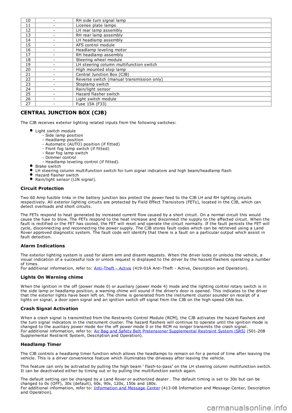
10-RH s i de turn s ignal lamp
11-Licens e pl ate lamps
12-LH rear l amp as s embl y13-RH rear lamp as s embly
14-LH headlamp as s embly
15-AFS cont rol module16-Headl amp l evel ing mot or
17-RH headlamp as s embly
18-Steering wheel modul e19-LH s t eering column mult ifunct ion s wit ch
20-High mount ed s top lamp
21-Central Junct ion Box (CJB)22-Revers e s wit ch (manual transmis si on only)
23-Stoplamp s wit ch
24-Rain/light s ensor25-Hazard flas her s wi tch
26-Light s wit ch modul e
27-Fuse 15A (F33)
CENTRAL JUNCTION BOX (CJB)
The CJB receives exteri or li ght ing relat ed inputs from t he fol lowing s wi tches:
Light s wit ch modul e- Side l amp pos it ion- Headlamp pos it ion- Automat ic (AUTO) posi ti on (if fi tt ed)- Front fog lamp swi tch (if fit ted)- Rear fog l amp s wit ch- Dimmer cont rol- Headlamp l evel ing control (if fit ted).Brake s wi tchLH s t eering column mult ifunct ion s wit ch for t urn si gnal i ndi cat ors and hi gh beam/headl amp flas hHazard flas her s wi tchRain/light s ensor (LIN si gnal ).
Circuit Protection
Two 60 Amp fus ibl e li nks in t he batt ery junct ion box protect the power feed to the CJB LH and RH li ght ing ci rcuit sres pect ively. All ext erior l ighti ng ci rcuit s are prot ect ed by Field Effect Trans is t ors (FETs ), l ocat ed in the CJB, which candetect overloads and s hort circuit s .
The FETs res pond to heat generated by increased current fl ow caus ed by a s hort ci rcuit . On a normal ci rcuit t his woul dcaus e t he fus e to bl ow. The FETs respond t o t he heat i ncrease and di s connect t he s uppl y t o t he affect ed ci rcuit . W hen t hefaul t is rect ified or t he FET has cool ed, t he FET wil l res et and operate t he circui t normall y. If t he faul t pers is ts the FET wi llcycle, di sconnect ing and reconnect ing t he power supply. The CJB s tores fault codes which can be ret rieved usi ng a LandRover approved diagnost ic sys tem. The fault code wil l identi fy t hat there is a fault on a part icular out put which as si s t infaul t det ect ion.
Alarm Indications
The exteri or li ght ing s ys tem is us ed for al arm arm and dis arm reques ts . W hen t he driver l ocks or unlocks the vehicle, avis ual i ndicat ion of a s uccess ful l ock or unlock reques t is di spl ayed t o t he dri ver by the hazard flas hers operat ing a numberof ti mes .For addit ional informat ion, refer t o: Anti -Theft - Act ive (419-01A Anti -Theft - Acti ve, Des cri pt ion and Operati on).
Lights On Warning chime
W hen t he i gni ti on in the off (power mode 0) or auxi liary (power mode 4) mode and the l ighti ng cont rol rotary swit ch is i nt he si de lamp or headlamp posi ti on, a warning chime wi ll s ound i f the driver's door is opened. This indicates t o t he dri vert hat t he exterior li ght s have been left on. The chime is generat ed from t he i ns t rument clus ter s ounder on receipt of ali ght s on s i gnal , a door open s ignal and an ignit ion swi tch off s ignal from t he CJB on the hi gh s peed CAN bus.
Crash Signal Activation
W hen a crash s ignal i s t rans mit ted from t he Rest rai nts Cont rol Modul e (RCM), t he CJB act ivat es the hazard flas hers andt he turn s ignal indicators in t he i ns t rument clus ter. The hazard fl ashers wil l continue to operate unt il t he ignit ion mode ischanged t o t he auxi liary power mode 4or the off power mode 0 or the RCM no longer trans mi ts the cras h si gnal .For addit ional informat ion, refer t o: Air Bag and Safet y Belt Pretens ioner Supplement al Res traint Syst em (SRS) (501-20BSuppl ement al Rest rai nt Sys tem, Des cri pti on and Operati on).
Headlamp Timer
The CJB cont rol s a headl amp t imer funct ion whi ch allows the headlamps t o remain on for a peri od of ti me after leaving t hevehi cl e. Thi s is a dri ver conveni ence feat ure which il lumi nat es t he dri veway after leaving t he vehicle.
This feat ure can onl y be acti vat ed by pulli ng t he high beam ' flas h-t o-pas s' on t he LH s t eering column mult ifunct ion s wi tch.It can be deacti vat ed eit her by ti ming out or by pull ing t he mul ti funct ion swi tch again.
The default s ett ing can be changed by a Land Rover or authorized deal er . The default t imi ng is s et t o 30s but can bechanged t o 0s (OFF), 30s (defaul t), 60s , 90s , 120s , 150s and 180s .For addit ional informat ion, refer t o: Informat ion and Mes s age Cent er (413-08 Informat ion and Mes s age Cent er, Des cript ionand Operat ion).
Page 2761 of 3229
41
Keys and remote controls
R
USING THE REMOTE CONTROL
Remote control
Note: The operational range of the remote
control will vary considerably depending on
atmospheric conditions and interference from
other transmitting devices.
The vehicle is supplied with two remote
controls, but up to six can be programmed to
the vehicle at any one time.
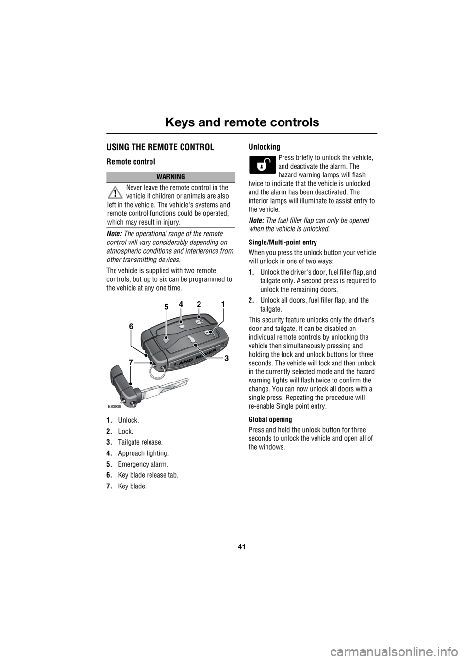
1. Unlock.
2. Lock.
3. Tailgate release.
4. Approach lighting.
5. Emergency alarm.
6. Key blade release tab.
7. Key blade.
Unlocking
Press briefly to unlock the vehicle,
and deactivate the alarm. The
hazard warning lamps will flash
twice to indicate that the vehicle is unlocked
and the alarm has been deactivated. The
interior lamps will illuminate to assist entry to
the vehicle.
Note: The fuel filler flap can only be opened
when the vehicle is unlocked.
Single/Multi- point entry
When you press the unlock button your vehicle
will unlock in one of two ways:
1. Unlock the driver's door, fuel filler flap, and
tailgate only. A second press is required to
unlock the remaining doors.
2. Unlock all doors, fuel filler flap, and the
tailgate.
This security feature unlocks only the driver’s
door and tailgate. It can be disabled on
individual remote controls by unlocking the
vehicle then simultaneously pressing and
holding the lock and unlock buttons for three
seconds. The vehicle will lock and then unlock
in the currently selected mode and the hazard
warning lights will flas h twice to confirm the
change. You can now unlock all doors with a
single press. Repeating the procedure will
re-enable Single point entry.
Global opening
Press and hold the unlock button for three
seconds to unlock the ve hicle and open all of
the windows.
WARNING
Never leave the remote control in the
vehicle if children or animals are also
left in the vehicle. The vehicle's systems and
remote control functions could be operated,
which may result in injury.
2
E80909
451
3
6
7
Page 2765 of 3229
45
Alarm
R
AlarmARMING THE ALARM
The engine is automatically
immobilised when the remote
control is removed from the starter
control unit. The alarm system is automatically
armed when the remote lock button is pressed.
The hazard lamps will flash to indicate that the
alarm is armed.
Full alarm
To set full alarm protection ensure that all the
windows and the sunroof are closed. Then
press the lock button twice within three
seconds. The hazard warn ing lights will flash
twice to confirm the alarm state.
Once fully armed the alarm will sound if :-
• the bonnet, tailgate, or a door are opened.
• movement is detected within the vehicle
interior.
• a window, front or rear windscreen, or
sunroof glass are broken.
• the vehicle is raised or tilted.
• the vehicle battery is disconnected.
• an attempt is made to disconnect the alarm
siren.
Note: If the alarm is armed and a window or the
sunroof are left open the alarm will sound due
to movement of air currents.
Partial alarm
To set partial alarm protection, briefly press the
lock button once. The hazard warning lights
will flash once to confirm the alarm state.
Once partially armed the alarm will sound if :-
• the bonnet, tailgate, or a door are opened.
• the vehicle battery is disconnected.
• an attempt is made to disconnect the alarm
siren. Note:
This setting should be used in
circumstances such as travelling on a ferry,
when pets are to be left in the vehicle, when a
window must be left open etc
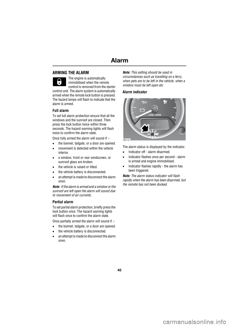
Alarm indicator
The alarm status is disp layed by the indicator.
• Indicator off - alarm disarmed.
• Indicator flashes once per second - alarm
is armed and engine immobilised.
• Indicator flashes rapidly - the alarm has
been triggered.
Note: The alarm status in dicator will flash
rapidly when the alarm has been disarmed, but
the remote has not been docked.
E81141
Page 2871 of 3229
151
Towing
R
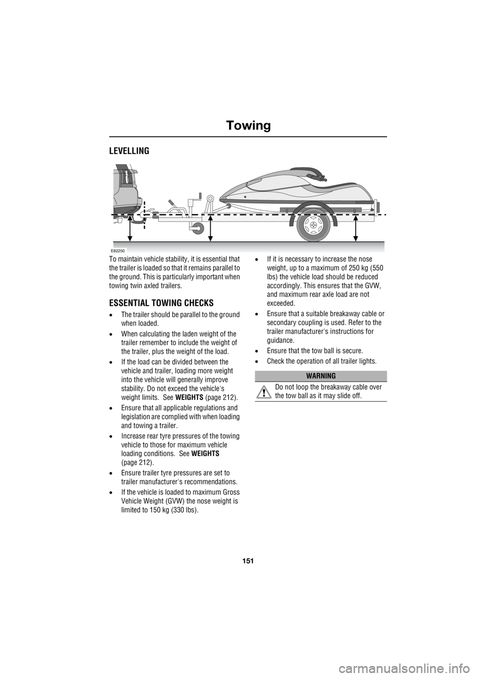
LEVELLING
To maintain vehicle stability, it is essential that
the trailer is loaded so that it remains parallel to
the ground. This is partic ularly important when
towing twin axled trailers.
ESSENTIAL TOWING CHECKS
• The trailer should be pa rallel to the ground
when loaded.
• When calculating the laden weight of the
trailer remember to include the weight of
the trailer, plus the weight of the load.
• If the load can be divided between the
vehicle and trailer, loading more weight
into the vehicle will generally improve
stability. Do not exceed the vehicle's
weight limits. See WEIGHTS (page 212).
• Ensure that all applic able regulations and
legislation are complied with when loading
and towing a trailer.
• Increase rear tyre pressures of the towing
vehicle to those for maximum vehicle
loading conditions. See WEIGHTS
(page 212).
• Ensure trailer tyre pressures are set to
trailer manufacture r's recommendations.
• If the vehicle is loaded to maximum Gross
Vehicle Weight (GVW) the nose weight is
limited to 150 kg (330 lbs). •
If it is necessary to increase the nose
weight, up to a maximum of 250 kg (550
lbs) the vehicle load should be reduced
accordingly. This ensures that the GVW,
and maximum rear axle load are not
exceeded.
• Ensure that a suitable breakaway cable or
secondary coupling is used. Refer to the
trailer manufacturer' s instructions for
guidance.
• Ensure that the tow ball is secure.
• Check the operation of all trailer lights.
E82250
WARNING
Do not loop the breakaway cable over
the tow ball as it may slide off.
Page 2874 of 3229
Vehicle care
154
L
Vehicle careCLEANING THE ALLOY WHEELS
Wash the wheels with soap and water, this
should be done more frequently when the
wheels are exposed to he avy dirt deposits, salt,
clay etc. If you are unsure how often to clean
the wheels in particular conditions, seek advice
from your Land Rover Dealer/Authorised
Repairer.
Land Rover approved wheel cleaner should be
used to remove heavy soiling.
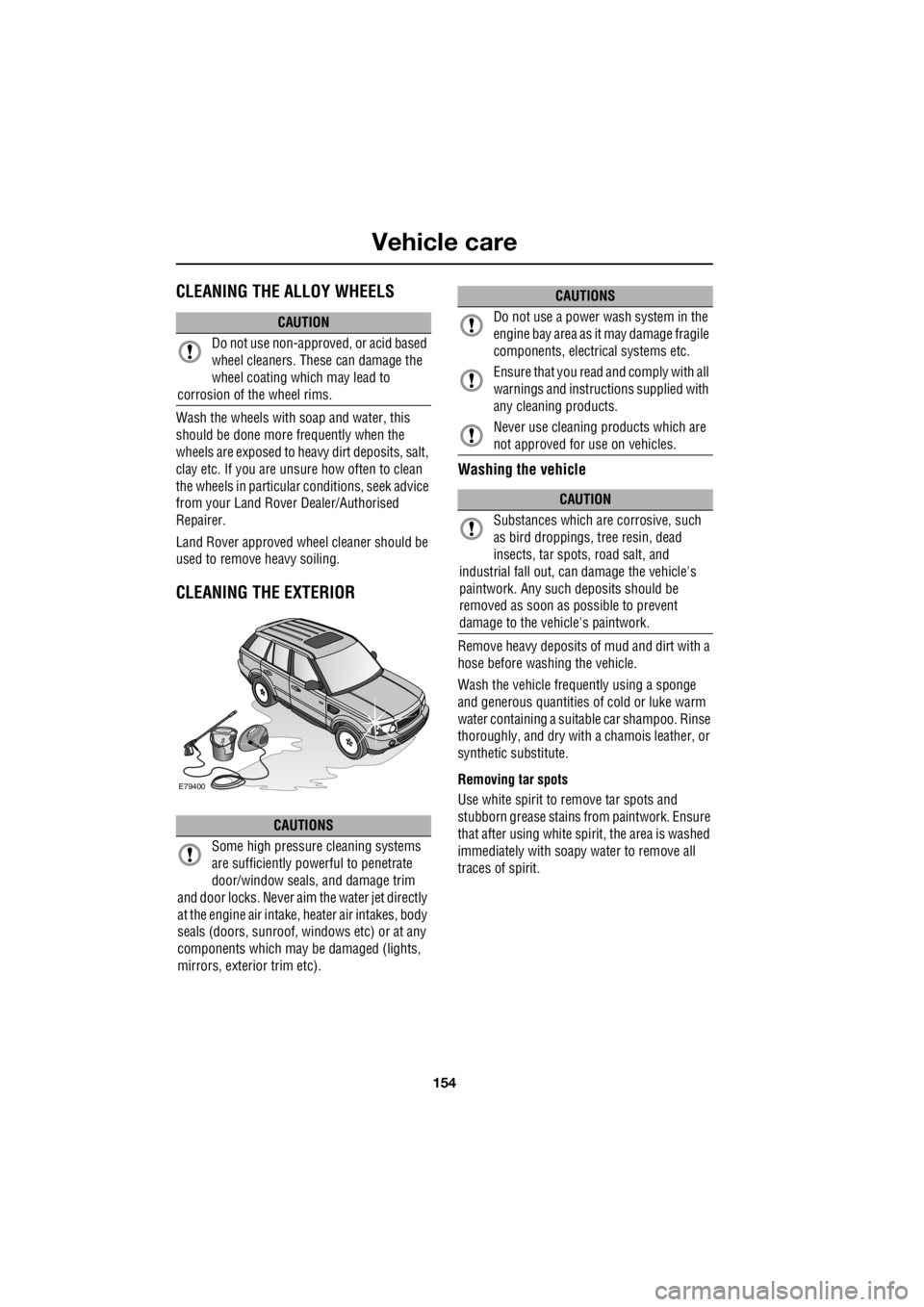
CLEANING THE EXTERIOR
Washing the vehicle
Remove heavy deposits of mud and dirt with a
hose before washing the vehicle.
Wash the vehicle frequently using a sponge
and generous quantities of cold or luke warm
water containing a suit able car shampoo. Rinse
thoroughly, and dry with a chamois leather, or
synthetic substitute.
Removing tar spots
Use white spirit to remove tar spots and
stubborn grease stains from paintwork. Ensure
that after using white spirit, the area is washed
immediately with soapy water to remove all
traces of spirit.
CAUTION
Do not use non-approved, or acid based
wheel cleaners. These can damage the
wheel coating which may lead to
corrosion of the wheel rims.
CAUTIONS
Some high pressure cleaning systems
are sufficiently pow erful to penetrate
door/window seals, and damage trim
and door locks. Never aim the water jet directly
at the engine air intake, heater air intakes, body
seals (doors, sunroof, windows etc) or at any
components which may be damaged (lights,
mirrors, exterior trim etc).
E79400
Do not use a power wash system in the
engine bay area as it may damage fragile
components, electrical systems etc.
Ensure that you read and comply with all
warnings and instruct ions supplied with
any cleaning products.
Never use cleaning products which are
not approved for use on vehicles.
CAUTION
Substances which are corrosive, such
as bird droppings, tr ee resin, dead
insects, tar spots, road salt, and
industrial fall out, can damage the vehicle's
paintwork. Any such deposits should be
removed as soon as possible to prevent
damage to the vehicle's paintwork.
CAUTIONS
Page 2879 of 3229
159
Maintenance
R
In addition, engine se ttings must not be
tampered with. These have been established to
ensure that your vehicle complies with
stringent exhaust em ission regulations.
Incorrect engine settings may adversely affect
exhaust emissions, engi ne performance and
fuel consumption. The y may also cause high
temperatures, which will result in damage to
the catalytic converter and the vehicle.
Road testing dynamometers (rolling
roads)
Because your vehicle is equipped with anti-lock
brakes and four wheel drive, it is essential that
any dynamometer testing is carried out only by
a qualified person, familiar with the
dynamometer testing an d safety procedures
practised by Land Rove r Dealers/Authorised
Repairers.
Safety in the garage
Fuel system
Poisonous fluids
Fluids used in motor vehicles are poisonous
and should not be consumed or brought into
contact with open wounds. These include;
battery acid, antifreeze, brake, clutch and
power steering fluid, petr ol, diesel, engine oil
and windscreen washer additives.
For your own safety, al ways read and obey all
instructions printed on labels and containers.
Used engine oil
Prolonged contact with engine oil may cause
serious skin disorders, including dermatitis
and cancer of the skin. Always wash
thoroughly after contact.
It is illegal to pollute drains, water
courses or soil. Use authorised
waste disposal sites to dispose of
used oil and toxic chemicals.
WARNINGS
If the vehicle has been driven recently,
do not touch exhaust and cooling
system components un til the engine has
cooled.
Never leave the engine running in an
unventilated area - exhaust gases are
poisonous and extremely dangerous.
Do not work beneath the vehicle with
the wheel changing jack as the only
means of support.
Keep your hands and clothing away
from drive belt s and pulleys.
Remove metal wr ist bands and
jewellery, before working in the engine
compartment.
Do not touch electrical leads or
components while the engine is
running, or with the starter switch turned on.
Do not allow tools or metal parts of the
vehicle to make contact with the battery
leads or terminals.
WARNINGS
Under no circumstances should any
part of the fuel system be dismantled or
replaced by anyone other than a suitably
qualified vehicle technician. Failure to comply
with this instruction, may result in fuel spillage
with a consequent serious risk of fire.
Ensure sparks and naked lights are kept
away from the engine compartment.
Wear protective cl othing, including,
where practicable, gloves made from
an impervious material.
WARNINGS
Page 2910 of 3229

Wheels and tyres
190
L
Using the Land Rover tyre repair kit
Note: All vehicle drivers and occupants should
be made aware that a temporary repair has
been made to a tyre fitted to the vehicle. They
should also be made aware of the special
driving conditions im posed when using a
repaired tyre. Repair procedure
1. Open the tyre repair kit and peel off the
maximum speed label. Attach the label to
the facia in the driver's field of view. Take
care not to obstruct any of the instruments
or warning lights.
2. Uncoil the compressor power cable and
the inflation hose.
3. Unscrew the orange cap from the sealant
bottle receiver, and the sealant bottle cap.
4. Screw the sealant bottle into the receiver
(clockwise) until tight.
• Screwing the bottle onto the receiver will
pierce the bottle's se al. Do not unscrew
a full, or partly us ed bottle from the
receiver. Doing so will result in the
sealant leaking from the bottle.
5. Remove the valve cap from the damaged
tyre.
6. Remove the protective cap from the
inflation hose, and c onnect the inflation
hose to the tyre valve. Ensure that the hose
is screwed on firmly.
7. Ensure that the compressor switch is in
the off ( O) position.
8. Insert the power cable connector into an
auxiliary power socket. See AUXILIARY
POWER SOCKETS (page 110).
9. Unless the vehicle is in an enclosed or
poorly ventilated area , start the engine.
10. Set the compressor switch to the on ( l)
position.
11. Inflate the tyre to a minimum of 1.8 bar (26
lb/in²) and a maximum of 3.5 bar (51
lb/in²).
†
WARNINGS
Avoid skin contact with the sealant
which contains natu ral rubber latex.
Do not unscrew the sealant bottle from the
receiver until it is empty, as sealant will leak
out.
If the tyre inflation pressure does not
reach 1.8 bar (26 lb/in²) within seven
minutes, the tyre may have suffered excessive
damage. A temporary repair will not be
possible, and the vehicle should not be driven
until the tyre has been replaced.
CAUTIONS
Before attempting a tyre repair, ensure
that the vehicle is parked safely, as far
away from passing traffic as possible.
Ensure that the parki ng brake is applied,
and P is selected if an automatic
transmission is fitted.
Do not attempt to remove foreign objects
such as nails, screws, etc from the tyre.
Always run the engine when using the
compressor, unless the vehicle is in an
enclosed, or poorly ventilated space.
To prevent overheating do not operate
the compressor continuously for longer
than ten minutes.