2006 LAND ROVER FRELANDER 2 open hood
[x] Cancel search: open hoodPage 547 of 3229
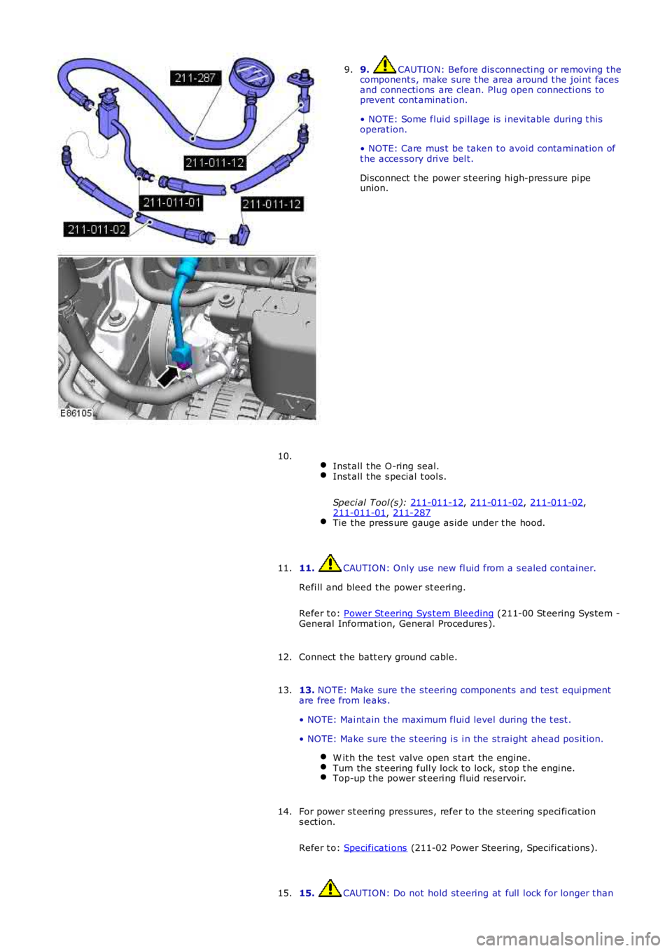
9. CAUTION: Before dis connecti ng or removing t he
component s, make sure t he area around t he joi nt faces
and connecti ons are clean. Plug open connecti ons to
prevent cont aminati on.
• NOTE: Some flui d s pill age is i nevi table during t his
operat ion.
• NOTE: Care mus t be taken t o avoid contami nat ion of
t he acces sory dri ve bel t.
Di sconnect t he power s t eering hi gh-pres s ure pi pe
union.
9.
Inst all t he O-ring seal. Inst all t he s pecial t ool s.
Speci al Tool (s ): 211-011-12 ,
211-011-02 ,
211-011-02 ,
211-011-01 ,
211-287 Tie the press ure gauge as ide under t he hood.10.
11. CAUTION: Only us e new fl uid from a s ealed container.
Refi ll and bleed t he power st eeri ng.
Refer t o: Power St eering Sys tem Bleeding (211-00 St eering Sys tem -
General Informat ion, General Procedures ).
11.
Connect t he batt ery ground cable.
12.
13. NOTE: Make sure t he s teeri ng components and tes t equi pment
are free from leaks .
• NOTE: Mai nt ain the maxi mum flui d level during t he t est .
• NOTE: Make s ure the s t eering i s i n the st rai ght ahead pos it ion. W it h the tes t val ve open s tart the engine. Turn the s t eering full y lock t o lock, st op t he engi ne.
Top-up t he power st eeri ng fl uid reservoi r.13.
For power s t eering press ures , refer to the s t eering s peci fi cat ion
s ect ion.
Refer t o: Specificati ons (211-02 Power Steering, Specificati ons ).
14.
15. CAUTION: Do not hold st eering at full l ock for longer t han
15.
Page 551 of 3229
Refer t o:
Air Cleaner (303-12A Intake Ai r Dis tribut ion and Fil tering -
I6 3.2L Pet rol, Removal and Ins t al lat ion).
3. CAUTION: Di scard fl ui d s iphoned from t he power st eeri ng
s yst em.
Siphon t he fl uid from t he power s t eering res ervoi r.
3.
Pos it ion an abs orbent cl oth t o coll ect fluid s pi ll age.
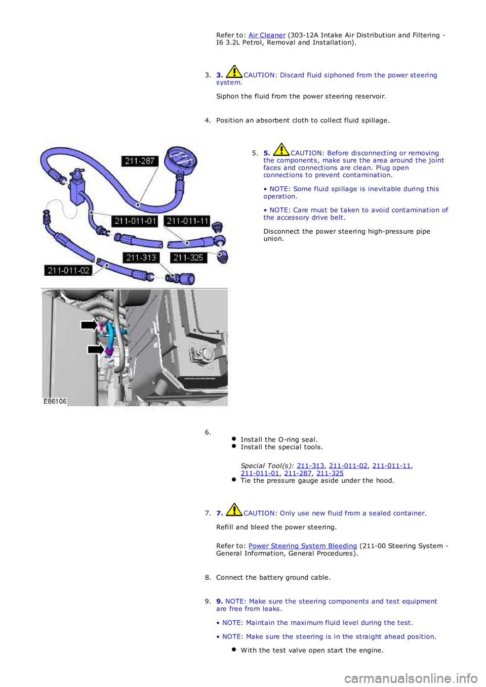
4. 5. CAUTION: Before di s connect ing or removi ng
the component s , make s ure t he area around the joint
faces and connect ions are clean. Pl ug open
connect ions t o prevent cont aminat ion.
• NOTE: Some fluid spi llage i s inevit able duri ng t hi s
operati on.
• NOTE: Care mus t be t aken to avoi d cont aminat ion of
the acces s ory drive belt .
Dis connect the power s teeri ng high-press ure pipe
uni on.
5.
Inst all t he O-ring seal. Inst all t he s pecial t ool s.
Speci al Tool (s ): 211-313 ,
211-011-02 ,
211-011-11 ,
211-011-01 ,
211-287 ,
211-325 Tie the press ure gauge as ide under t he hood.6.
7. CAUTION: Only use new fl uid from a s ealed container.
Refi ll and bleed t he power st eeri ng.
Refer t o: Power St eering Sys tem Bleeding (211-00 St eering Sys tem -
General Informat ion, General Procedures ).
7.
Connect t he batt ery ground cable.
8.
9. NOTE: Make s ure t he s teeri ng component s and tes t equipment
are free from leaks .
• NOTE: Mai nt ain the maxi mum flui d level during t he t est .
• NOTE: Make s ure the s t eering i s i n the st rai ght ahead pos it ion. W it h the tes t val ve open s tart the engine. 9.
Page 915 of 3229
1
1
1
1
PINPOINT TEST B : THE ENGINE OVERHEATS
T ESTCONDIT IONSDET AILS/RESULT S/ACT IO NS
B1: CHECK CO OLANT
W ARNING: The cool ing s yst em is pres s uri zed! Ensure t he res ervoir cap i s never rel eased unt il t he sys t em has cool ed.Fail ure t o fol low thes e ins t ructi ons may res ult i n pers onal i njury.
Check t he cool ant l evel and condi ti on.
Does the s ys tem cont ai n s ufficient cool ant of t he correct s peci fi cat ion?YesGO t o B2.NoTop-up and fi ll t he cool ing s ys tem to the correct l evel wi th the correct s pecifi cat ion flui d asneces sary.REFER t o: Speci ficat ions (303-03A Engi ne Cool ing - I6 3.2L Pet rol , Specificati ons ) /Cool ing Sys tem Drai ni ng, Fi lli ng and Bleeding (303-03A Engine Cooli ng - I6 3.2L Pet rol, GeneralProcedures ).Check for coolant los s . GO t o B1.
B2: CHECK CO OLANT EXPANSION T ANK PRESSURE CAP
Check t he cool ant expansi on tank press ure cap for damage/correct operati on. REFER t o t he cool antexpans ion t ank pres sure cap pres sure t est i n t his s ect ion.
Is t he coolant expans ion t ank pres sure cap operati ng correctl y?YesGO t o B3.NoINSTALL a new coolant expans ion t ank pres s ure cap. TEST t he s yst em for correct operati on.
B3: CHECK T HERMOST ATCheck t he t hermos tat for correct operat ion. REFER to the t hermos t at component t es t in t hissect ion.Is t he t hermos tat operat ing correct ly?YesCheck for correct operat ion of cooli ng fans , ci rcuit s , sens ors , modules , et c.REFER t o: Electroni c Engine Controls (303-14A Electronic Engine Controls - I6 3.2L Pet rol , Diagnosi sand Tes t ing).NoINSTALL a new t hermos t at .REFER t o: Thermos tat (303-03A Engine Cooli ng - I6 3.2L Petrol, Removal and Ins tall ati on).TEST the s ys tem for correct operat ion.
PINPOINT TEST C : THE ENG INE DOES NOT REACH NORMAL OPERATING TEMPERATURE
T ESTCONDIT IONSDET AILS/RESULT S/ACT IONS
C1: CHECK T HERMOST ATCheck the thermos t at for correct operat ion. REFER t o t he t hermos tat component t est in t hiss ecti on.
Is t he thermost at operati ng correctl y?YesCheck for correct operat ion of cool ing fans, circui ts , s ensors, modul es , et c.REFER t o: El ect roni c Engi ne Cont rol s (303-14A Elect roni c Engi ne Cont rol s - I6 3.2L Pet rol,Di agnos is and Tes t ing).NoINSTALL a new t hermos tat .REFER t o: Thermost at (303-03A Engi ne Cool ing - I6 3.2L Pet rol , Removal and Inst all at ion).TEST t he s ys t em for correct operati on.
Component Tests
Cooling System Pressure Test
W ARNING: Never, under any ci rcums tances, remove the coolant expans ion tank pres s ure cap whi le t he engine i soperati ng. To avoid havi ng s caldi ng hot water or s team bl ow out of the cooli ng s ys t em, use ext reme care when removi ngt he coolant expans ion tank pres s ure cap from a hot cool ing s ys tem. W ai t unti l the engine has cooled, then wrap a t hickcloth around t he coolant expans ion tank pres s ure cap and t urn it s lowl y unt il t he pres s ure begins t o releas e, s t ep backwhil e t he pres sure i s rel eas ed from the s ys tem. W hen certai n all t he pres s ure has been rel eas ed (s ti ll wit h a cl oth) t urnand remove t he coolant expans ion t ank pres sure cap. Fail ure t o follow thes e i ns t ructi ons may res ult i n damage t o t hecool ing s ys tem, engine and/or cause pers onal injury.
1. Swit ch the engine off.1.
2. Open the hood and i nst all prot ect ive fender covers .2.
3. Careful ly remove the coolant expans ion t ank pres s ure cap from the coolant expans ion t ank to rel ieve pres s ure i nt he cool ing s ys tem. Add coolant t o cool ant expans i on tank as necess ary.3.
4. Ins t al l the press ure tes t er equipment t o t he cool ing s yst em foll owing manufact urers i nst ruct ions. Rei ns t all t hecoolant expans ion t ank pres sure cap (if pres s ure t est equipment i s not ins tal led t o t he cool ant expans i on tank).4.
5. Pres surize t he cool ing s ys tem to the coolant expans ion t ank pres s ure cap lower l imi t.5.
6. Observe the gauge readi ng for approximat ely t wo minutes . Pres s ure s houl d not drop during t his t ime.
If sys tem holds pres s ure, cont inue from s tep 8.
6.
Page 942 of 3229
ItemPart NumberDescription
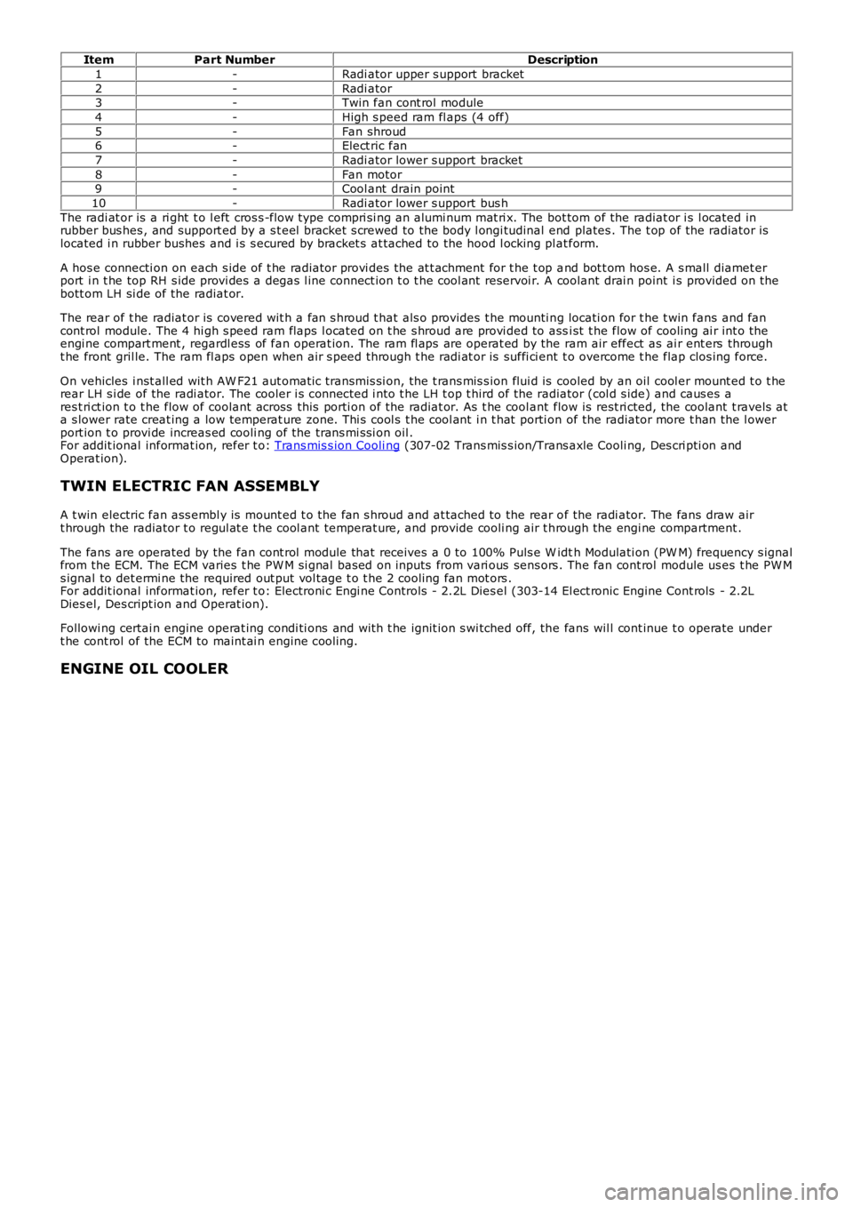
1-Radi ator upper s upport bracket
2-Radi ator3-Twin fan cont rol module
4-High s peed ram fl aps (4 off)
5-Fan shroud6-Elect ric fan
7-Radi ator lower s upport bracket
8-Fan motor9-Cool ant drain point
10-Radi ator lower s upport bus h
The radi at or is a ri ght t o l eft cros s -flow type compri si ng an alumi num mat ri x. The bot tom of the radiat or i s l ocated inrubber bus hes , and support ed by a s t eel bracket s crewed to the body l ongi tudinal end plates . The t op of the radiator i slocated i n rubber bushes and i s s ecured by bracket s at tached to the hood l ocking pl at form.
A hos e connecti on on each s ide of t he radiat or provi des the at t achment for t he t op and bot t om hos e. A s mall diamet erport i n t he top RH s ide provi des a degas l ine connect ion t o t he cool ant reservoi r. A coolant drai n point i s provided on t hebott om LH si de of the radiat or.
The rear of t he radiat or is covered wit h a fan s hroud t hat als o provides t he mounti ng locati on for t he t win fans and fancont rol module. The 4 hi gh s peed ram flaps l ocat ed on t he s hroud are provi ded to assi st t he flow of cooling ai r int o t heengi ne compart ment , regardl ess of fan operat ion. The ram fl aps are operat ed by the ram air effect as ai r ent ers throught he front gril le. The ram fl aps open when air s peed through t he radi at or is suffi ci ent t o overcome t he flap clos ing force.
On vehicles i nst all ed wit h AW F21 aut omati c transmis si on, the t rans mis s ion flui d is cooled by an oil cool er mount ed t o t herear LH s i de of the radi ator. The cooler i s connected i nto t he LH t op t hird of the radiator (col d s ide) and caus es ares t ri ct ion t o t he flow of coolant across this porti on of the radiat or. As t he cool ant flow is rest ri cted, the coolant t ravels ata s lower rate creat ing a low temperat ure zone. Thi s cool s t he cool ant i n t hat porti on of the radiator more t han the l owerport ion t o provi de increas ed cooli ng of the trans mi s si on oil .For addit ional informat ion, refer t o: Trans mis s ion Cooli ng (307-02 Trans mis s ion/Trans axle Cooli ng, Des cri pti on andOperat ion).
TWIN ELECTRIC FAN ASSEMBLY
A t win electric fan ass embl y is mount ed t o the fan s hroud and at tached to the rear of the radi ator. The fans draw airt hrough the radiator t o regul at e t he cool ant temperat ure, and provide cooli ng air t hrough the engi ne compartment .
The fans are operated by the fan cont rol module that receives a 0 to 100% Puls e W idth Modulati on (PW M) frequency s ignalfrom the ECM. The ECM varies t he PW M si gnal bas ed on inputs from vari ous sens ors . The fan cont rol module us es t he PW Ms ignal to det ermi ne the required out put vol tage t o t he 2 cooling fan mot ors .For addit ional informat ion, refer t o: Electroni c Engi ne Controls - 2.2L Dies el (303-14 El ect ronic Engine Cont rols - 2.2LDies el, Des cript ion and Operat ion).
Followi ng certai n engine operat ing condi ti ons and wit h t he ignit ion s wi tched off, the fans wil l cont inue t o operate undert he cont rol of the ECM to maint ai n engine cooling.
ENGINE OIL COOLER
Page 949 of 3229
1
1
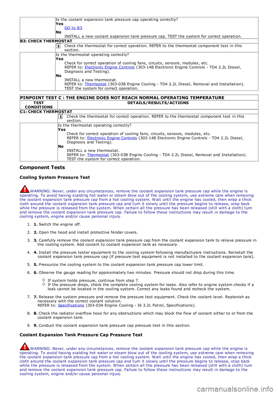
Is t he coolant expans ion t ank pres sure cap operati ng correctl y?
Yes GO t o B3 .
No INSTALL a new coolant expans ion t ank pres s ure cap. TEST t he s yst em for correct opera ti on.
B3: CHECK T HERMOST AT Check t he t hermos tat for correct operat ion. REFER to the t hermos t at component t es t i n t his
sect ion.
Is t he t hermos tat operat ing correct ly?
Yes
Check for correct operat ion of cooli ng fans , ci rcuit s , sens ors , modules , et c.
REFER t o: Electroni c Engine Controls (303-14B Electronic Engine Controls - TD4 2.2L Dies el,
Diagnos i s and Test ing).
No
INSTALL a new t hermos t at .
REFER t o: Thermos tat (303-03B Engine Cooli ng - TD4 2.2L Di esel , Removal and Ins t allat ion).
TEST the s ys tem for correct operat ion.
PINPOINT TEST C : THE ENG INE DOES NOT REACH NORMAL OPERATING TEMPERATURE T EST
CONDIT IONS DET AILS/RESULT S/ACT IONS
C1: CHECK T HERMOST AT Check t he thermost at for correct operat ion. REFER to t he t hermos tat component t est i n t his
secti on.
Is t he t hermos tat operati ng correct ly?
Yes Check for correct operat ion of cooling fans , ci rcuit s, s ens ors , modul es, et c.
REFER t o: Electroni c Engi ne Control s (303-14B Electroni c Engi ne Controls - TD4 2.2L Dies el,
Diagnos is and Tes t ing).
No INSTALL a new t hermos tat .
REFER t o: Thermos tat (303-03B Engi ne Cooling - TD4 2.2L Di es el, Removal and Ins t al lat ion).
TEST t he s yst em for correct operati on.
Component Tests
Cooling System Pressure Test W ARNING: Never, under any ci rcums tances, remove the coolant expans ion tank pres s ure
cap whi le t he engine i s
operati ng. To avoid havi ng s caldi ng hot water or s team bl ow out of the cooli ng s ys t e m, use ext reme care when removi ng
t he coolant expans ion tank pres s ure cap from a hot cool ing s ys tem. W ai t unti l the en gine has cooled, then wrap a t hick
cloth around t he coolant expans ion tank pres s ure cap and t urn it s lowl y unt il t he pr es s ure begins t o releas e, s t ep back
whil e t he pres sure i s rel eas ed from the s ys tem. W hen certai n all t he pres s ure has be en rel eas ed (s ti ll wit h a cl oth) t urn
and remove t he coolant expans ion t ank pres sure cap. Fail ure t o follow thes e i ns t ruct i ons may res ult i n damage t o t he
cool ing s ys tem, engine and/or cause pers onal injury.
1. Swit ch the engine off.
1.
2. Open the hood and i nst all prot ect ive fender covers .
2.
3. Careful ly remove the coolant expans ion t ank pres s ure cap from the coolant expans ion t ank to rel ieve pres s ure i n
t he cool ing s ys tem. Add coolant t o cool ant expans i on tank as necess ary.
3.
4. Ins t al l the press ure tes t er equipment t o t he cool ing s yst em foll owing manufact urers i nst ruct ions. Rei ns t all t he
coolant expans ion t ank pres sure cap (if pres s ure t est equipment i s not ins tal led t o t he cool ant expans i on tank).
4.
5. Pres surize t he cool ing s ys tem to the coolant expans ion t ank pres s ure cap lower l imi t .
5.
6. Observe the gauge readi ng for approximat ely t wo minutes . Pres s ure s houl d not drop du ring t his t ime.
If sys tem holds pres s ure, cont inue from s tep 7. If the pres s ure drops, check the complet e cool ing s ys tem for l eaks . Als o refer to en
gi ne s ys t em checks i f a
leak cannot be locat ed in the cooli ng s ys t em. Correct any leaks found and recheck t h e s ys t em.6.
7. Release the s ys tem pres s ure and remove the press ure tes t equipment. Check the coolan t level. Replenis h as
necess ary wit h t he correct cool ant s olut ion.
REFER t o: Specificati ons (303-03A Engine Cooli ng - I6 3.2L Pet rol, Specifi cat ions ).
7.
8. Check t he radi at or overfl ow hos e for any obs truct ions which may block the flow of co olant eit her to or from t he
coolant expans ion t ank.
8.
9. Conduct the coolant expans ion t ank pres s ure cap pres s ure t es t in t his secti on.
9.
Coolant Expansion Tank Pressure Cap Pressure Test W ARNING: Never, under any ci rcums tances, remove the coolant expans ion tank pres s ure
cap whi le t he engine i s
operati ng. To avoid havi ng s caldi ng hot water or s team bl ow out of the cooli ng s ys t e m, use ext reme care when removi ng
t he coolant expans ion tank pres s ure cap from a hot cool ing s ys tem. W ai t unti l the en gine has cooled, then wrap a t hick
cloth around t he coolant expans ion tank pres s ure cap and t urn it s lowl y unt il t he pr es s ure begins t o releas e, s t ep back
whil e t he pres sure i s rel eas ed from the s ys tem. W hen certai n all t he pres s ure has be en rel eas ed (s ti ll wit h a cl oth) t urn
and remove t he coolant expans ion t ank pres sure cap. Fail ure t o follow thes e i ns t ruct i ons may res ult i n damage t o t he
cool ing s ys tem, engine and/or cause pers onal injury.
Page 1109 of 3229
Fuel fired heat er
The FFBH (fuel fired boost er heat er) and St op/Start s ys t em wi ll not operate si mult aneous ly, due to low ambientt emperatures bei ng a fact or in t he funct ion of both sys tems .
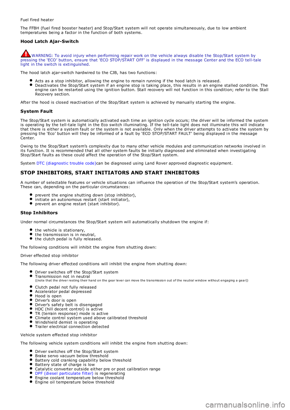
Hood Latch Ajar-Switch
W ARNING: To avoi d injury when performing repai r work on t he vehicle al ways di s abl e the Stop/St art s ys tem bypres s ing t he ‘ECO’ butt on, ens ure that ‘ECO STOP/START OFF’ is di s pl ayed in t he mes sage Cent er and the ECO tel l-taleli ght in t he s wit ch is ext inguis hed.
The hood lat ch ajar-s wit ch hardwired to the CJB, has two functi ons :
Acts as a s top i nhi bit or, all owing t he engi ne t o remai n running if t he hood latch i s rel eased.Deact ivates the St op/Start s ys t em i f an engi ne s top i s t aki ng place, t his res ul ts in an engine st all ed condit ion. Theengi ne can be res t art ed usi ng t he ignit ion but ton. Stal l recovery wil l not funct ion i n t hi s condi ti on; refer t o t he StallRecovery secti on.
Aft er the hood i s clos ed reacti vat ion of t he Stop/Start sys tem is achieved by manuall y s tarti ng the engine.
System Fault
The Stop/St art s ys tem is aut omati cal ly acti vat ed each ti me an ignit ion cycl e occurs; t he dri ver will be i nformed t he sys t emis operat ing by the t ell -t ale l ight in the Eco s wi tch i lluminati ng. If the tell -t ale light does not il luminat e t hi s wi ll indicat et hat t here i s eit her a s ys t em faul t or the sys tem is not avail abl e. Onl y when t he dri ver at tempt s t o act ivat e t he sys t em bypres s ing t he ‘Eco’ but ton will t hey be informed of a fault by ‘ECO STOP/START FAULT’ being di spl ayed i n t he mes sageCenter.
Owi ng to the St op/Start s ys t em’s complexit y due t o many ot her vehicle modul es and communicat ion net works i nvol ved i nit s funct ion. It i s recommended t hat al l ot her sys tem faul ts be init ial ly diagnos ed and eliminated when inves t igati ngStop/St art fault s as t hes e could affect the operat ion of t he St op/Start sys tem.
Syst em DTC (di agnos ti c troubl e code)can be diagnos ed us ing Land Rover approved di agnos ti c equi pment.
STOP INHIBITORS, START INITIATORS AND START INHIBITORS
A number of s el ect able feat ures or vehicle si tuat ions can infl uence t he operat ion of t he Stop/St art s yst em’s operati on.Thes e can, depending on the parti cular circumst ances :
prevent the engine s hutt ing down (s t op inhibi tor),ini ti at e an aut onomous res tart (s tart ini ti at or),prevent an engi ne res t art (st art i nhi bit or).
Stop Inhibitors
Under normal ci rcums tances the St op/St art s ys t em wi ll automat icall y s hut down t he engi ne if:
t he vehi cl e is st ati onary,t he trans mi s si on is in neutral,t he cl utch pedal i s ful ly releas ed.
The fol lowing condit ions wi ll inhibi t the engine from s hutt ing down:
Dri ver effected st op inhi bi tor
The fol lowing driver effect ed condi ti ons will i nhi bit t he engi ne from shut ti ng down:
Dri ver s wi tches off t he Stop/St art s ys temTrans mis s ion not i n neut ral((no te that the d rive r re sting their ha nd o n the g ea r le ve r ca n move the tra ns mis sion o ut o f the ne utra l w ind o w w itho ut e nga g ing a ge a r))
Clut ch pedal not full y rel easedAccelerator pedal depres s edHood is openDri ver’s door is openDri ver’s safet y belt i s dis engagedHDC (hil l decent cont rol) i s acti veTR (terrain res pons e) mode i s act iveCli mate cont rol s ys t em us ed above cal ibrat ed thresholdW i nds hiel d demis t i s operati ngTrai ler electrical connect ion det ect ed
Vehicle s ys tem effect ed s top i nhi bit or
The fol lowing vehicl e s ys t em condi ti ons wil l inhibit t he engine from s hut ti ng down:
Dri ver s wi tches off t he Stop/St art s ys temBrake s ervo vacuum below thres holdBatt ery cold cranki ng capabil it y below t hres holdBatt ery s t ate of charge i s lowCatal yt ic converter out si de eit her pre or post cali brati on rangeDPF (di esel part iculat e filt er) i s regenerat ingEngi ne cool ant temperat ure bel ow t hreshol dEngi ne oil t emperature below thres hold
Page 1110 of 3229
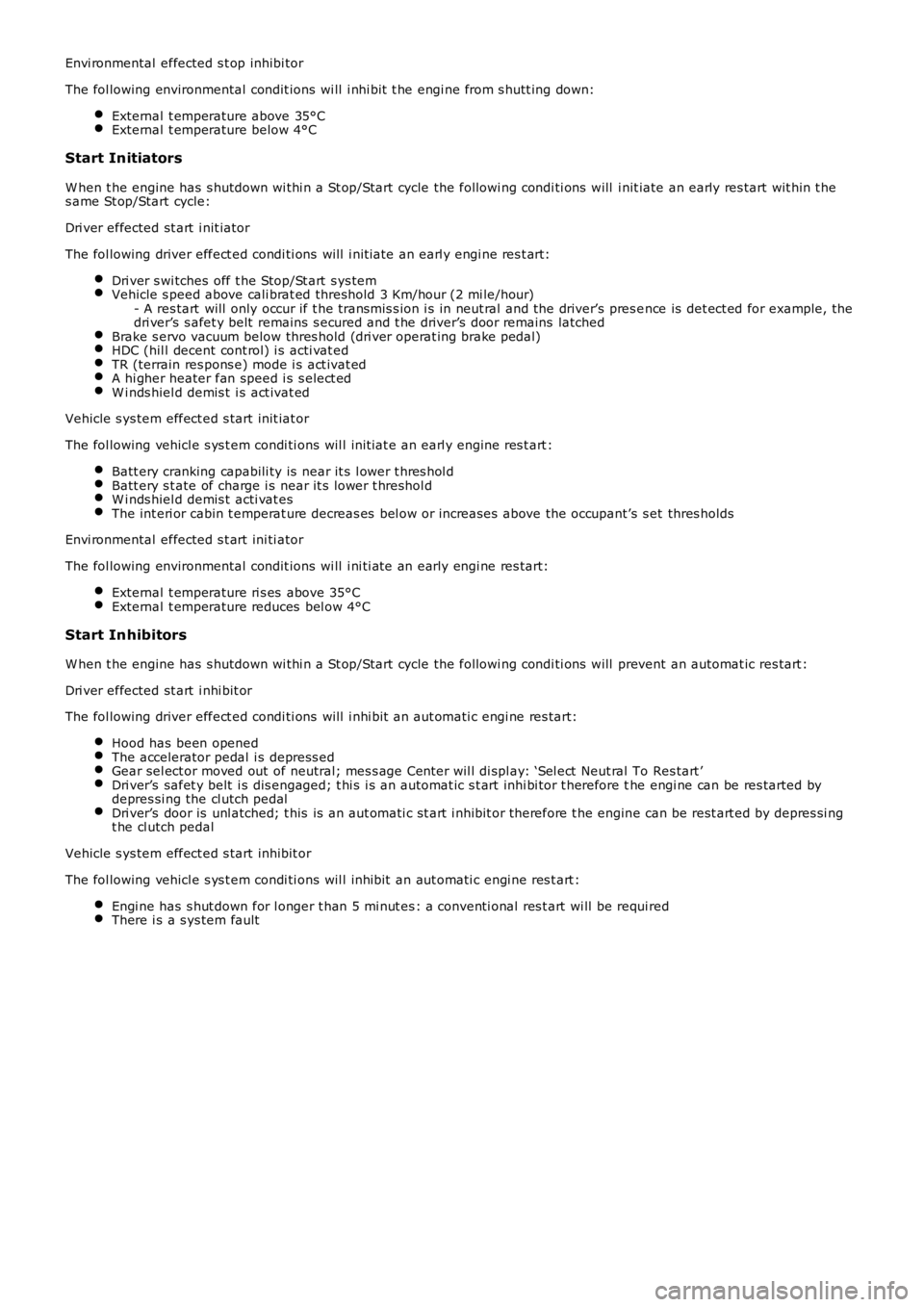
Envi ronmental effected s t op inhibi tor
The fol lowing environmental condit ions wi ll i nhi bit t he engi ne from s hutt ing down:
External t emperature above 35°CExternal t emperature below 4°C
Start Initiators
W hen t he engine has s hutdown wi thi n a St op/Start cycle the followi ng condi ti ons will i nit iate an early res tart wit hin t hes ame St op/Start cycle:
Dri ver effected st art i nit iator
The fol lowing driver effect ed condi ti ons will i nit iate an earl y engi ne res t art:
Dri ver s wi tches off t he Stop/St art s ys temVehicle s peed above cali brat ed threshold 3 Km/hour (2 mi le/hour)- A res tart will only occur if t he transmis s ion i s in neut ral and the driver’s pres ence is det ect ed for example, thedri ver’s s afet y belt remains s ecured and t he driver’s door remains latchedBrake s ervo vacuum below thres hold (dri ver operat ing brake pedal)HDC (hil l decent cont rol) i s acti vat edTR (terrain res pons e) mode i s act ivat edA hi gher heater fan speed i s s elect edW i nds hiel d demis t i s act ivat ed
Vehicle s ys tem effect ed s tart init iat or
The fol lowing vehicl e s ys t em condi ti ons wil l init iat e an earl y engine res t art :
Batt ery cranking capabili ty is near it s l ower t hres hol dBatt ery s t ate of charge i s near it s lower t hreshol dW i nds hiel d demis t acti vat esThe int eri or cabin t emperat ure decreas es bel ow or increas es above the occupant’s s et thres holds
Envi ronmental effected s t art ini ti ator
The fol lowing environmental condit ions wi ll i ni ti ate an early engi ne res tart:
External t emperature ri s es above 35°CExternal t emperature reduces bel ow 4°C
Start Inhibitors
W hen t he engine has s hutdown wi thi n a St op/Start cycle the followi ng condi ti ons will prevent an automat ic res tart :
Dri ver effected st art i nhi bit or
The fol lowing driver effect ed condi ti ons will i nhi bit an aut omati c engi ne res tart:
Hood has been openedThe accelerator pedal i s depress edGear sel ect or moved out of neutral; mes s age Cent er wil l di spl ay: ‘Sel ect Neut ral To Res tart ’Dri ver’s safet y belt i s dis engaged; t hi s i s an automat ic s t art inhi bi tor t herefore the engi ne can be res tarted bydepres si ng the cl utch pedalDri ver’s door is unl atched; t his is an aut omati c st art i nhibit or therefore t he engine can be rest art ed by depres si ngt he cl utch pedal
Vehicle s ys tem effect ed s tart inhibit or
The fol lowing vehicl e s ys t em condi ti ons wil l inhibit an aut omati c engi ne res t art :
Engi ne has s hut down for l onger t han 5 mi nut es : a conventi onal res t art wi ll be requi redThere i s a s ys tem fault
Page 1790 of 3229
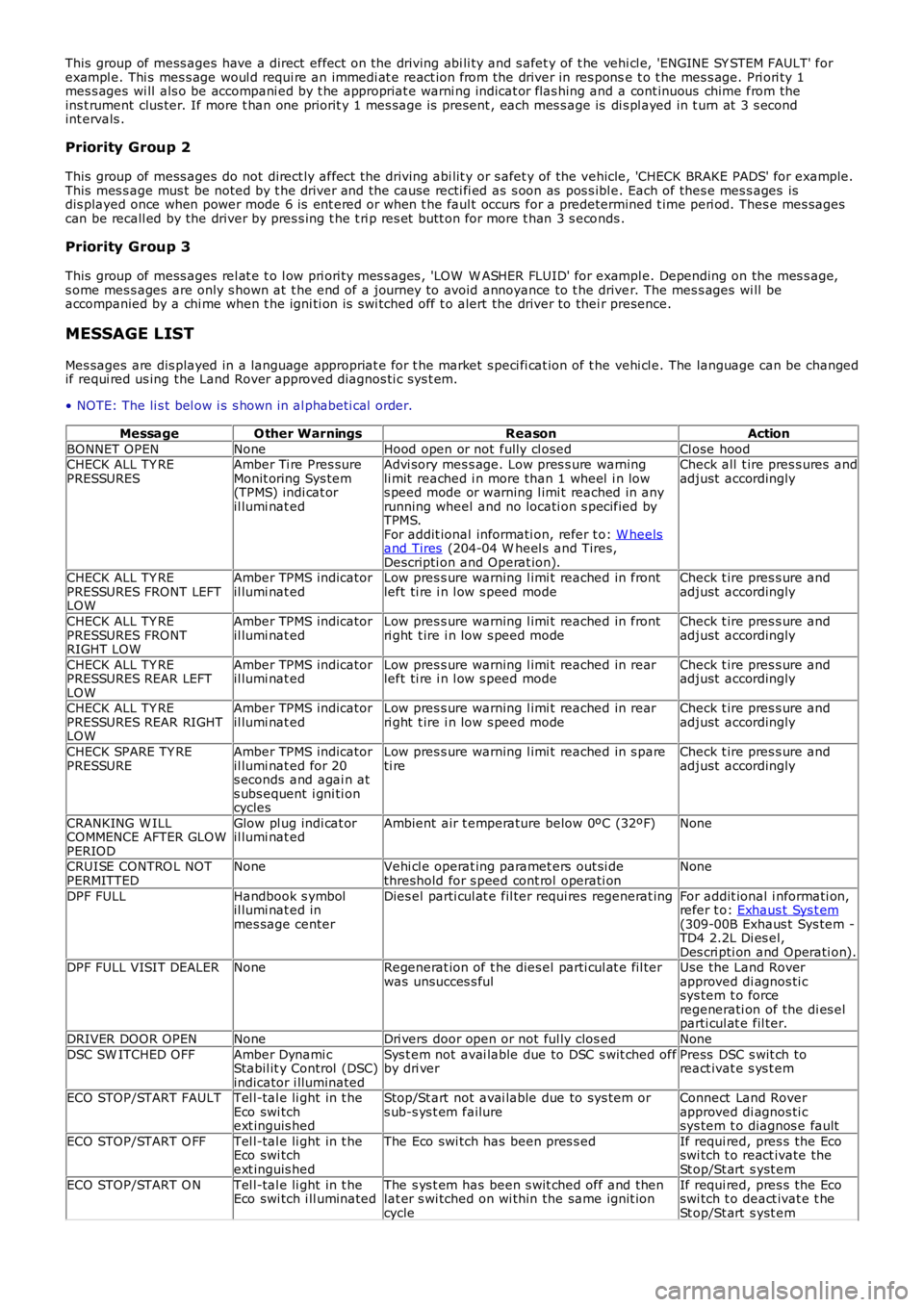
This group of mess ages have a direct effect on the driving abi li ty and s afet y of t he vehi cl e, 'ENGINE SY STEM FAULT' forexampl e. Thi s mes s age woul d requi re an immedi at e react ion from the driver in res ponse t o t he mes s age. Pri ori ty 1mes s ages wi ll als o be accompani ed by t he appropriat e warni ng indicat or flas hing and a cont inuous chime from theins t rument clus ter. If more t han one priorit y 1 mes s age is present , each mes s age is di s pl ayed in t urn at 3 s econdint ervals .
Priority Group 2
This group of mess ages do not direct ly affect the driving abi lit y or s afet y of the vehicle, 'CHECK BRAKE PADS' for example.This mes s age mus t be noted by t he driver and the cause recti fi ed as s oon as pos s ibl e. Each of thes e mes s ages isdis played once when power mode 6 is ent ered or when t he faul t occurs for a predetermined t ime peri od. Thes e mes sagescan be recall ed by the driver by pres s ing t he t ri p res et butt on for more t han 3 s econds .
Priority Group 3
This group of mess ages rel at e t o l ow pri ori ty mes s ages , 'LOW W ASHER FLUID' for exampl e. Depending on the mes s age,s ome mes s ages are only s hown at t he end of a journey to avoid annoyance to t he driver. The mes s ages wi ll beaccompanied by a chi me when t he igni ti on is s wi tched off t o alert the driver to their presence.
MESSAGE LIST
Mes sages are dis played in a language appropriat e for t he market s peci fi cat ion of t he vehi cl e. The language can be changedif requi red us ing the Land Rover approved diagnos ti c sys t em.
• NOTE: The li s t bel ow i s s hown in al phabeti cal order.
MessageO ther WarningsReasonAction
BONNET OPENNoneHood open or not fully cl osedCl ose hoodCHECK ALL TY REPRESSURESAmber Ti re Pres sureMonit oring Sys tem(TPMS) indi cat oril lumi nat ed
Advi sory mes s age. Low pres s ure warningli mit reached i n more than 1 wheel i n lows peed mode or warning l imi t reached in anyrunning wheel and no locati on s pecified byTPMS.For addit ional informati on, refer t o: W heelsand Tires (204-04 W heel s and Tires,Descripti on and Operat ion).
Check all t ire pres s ures andadjust accordingly
CHECK ALL TY REPRESSURES FRONT LEFTLOW
Amber TPMS indicatoril lumi nat edLow pres s ure warning l imi t reached in frontleft ti re i n l ow s peed modeCheck t ire pres s ure andadjust accordingly
CHECK ALL TY REPRESSURES FRONTRIGHT LOW
Amber TPMS indicatoril lumi nat edLow pres s ure warning l imi t reached in frontri ght t ire i n low s peed modeCheck t ire pres s ure andadjust accordingly
CHECK ALL TY REPRESSURES REAR LEFTLOW
Amber TPMS indicatoril lumi nat edLow pres s ure warning l imi t reached in rearleft ti re i n l ow s peed modeCheck t ire pres s ure andadjust accordingly
CHECK ALL TY REPRESSURES REAR RIGHTLOW
Amber TPMS indicatoril lumi nat edLow pres s ure warning l imi t reached in rearri ght t ire i n low s peed modeCheck t ire pres s ure andadjust accordingly
CHECK SPARE TY REPRESSUREAmber TPMS indicatoril lumi nat ed for 20s econds and agai n ats ubs equent i gni ti oncycles
Low pres s ure warning l imi t reached in s pareti reCheck t ire pres s ure andadjust accordingly
CRANKING W ILLCOMMENCE AFTER GLOWPERIOD
Glow pl ug indi cat oril lumi nat edAmbient air t emperature below 0ºC (32ºF)None
CRUISE CONTRO L NOTPERMITTEDNoneVehi cl e operat ing paramet ers out si dethreshold for s peed cont rol operati onNone
DPF FULLHandbook s ymbolil lumi nat ed inmes sage center
Dies el parti cul at e fil ter requi res regenerat ingFor addit ional i nformati on,refer t o: Exhaus t Sys t em(309-00B Exhaus t Sys tem -TD4 2.2L Di es el,Des cri pti on and Operati on).DPF FULL VISIT DEALERNoneRegenerat ion of t he dies el parti cul at e fil terwas unsucces s fulUse the Land Roverapproved di agnos ti csys tem t o forceregenerati on of the di es elparti cul at e fil ter.
DRIVER DOOR OPENNoneDri vers door open or not ful ly clos edNone
DSC SW ITCHED OFFAmber Dynami cStabil it y Control (DSC)indicator i lluminated
Sys t em not avai lable due to DSC s wit ched offby dri verPress DSC s wit ch toreact ivat e s ys t em
ECO STOP/START FAULTTel l-tal e li ght in t heEco swi tchext inguis hed
Stop/St art not avai lable due to sys tem ors ub-s ys t em failureConnect Land Roverapproved di agnos ti csys tem t o diagnos e fault
ECO STOP/START O FFTel l-tal e li ght in t heEco swi tchext inguis hed
The Eco swi tch has been pres s edIf requi red, pres s the Ecoswi tch t o react ivate theSt op/St art s yst em
ECO STOP/START O NTel l-tal e li ght in t heEco swi tch i ll uminatedThe s ys t em has been s wit ched off and thenlat er s wi tched on wi thin the same ignit ioncycle
If requi red, pres s the Ecoswi tch t o deact ivat e t heSt op/St art s yst em