2006 LAND ROVER FRELANDER 2 brakes
[x] Cancel search: brakesPage 451 of 3229
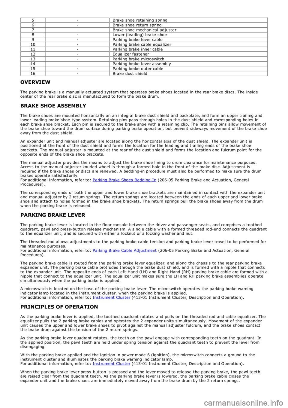
5-Brake shoe retai ni ng s pri ng
6-Brake shoe return s pri ng
7-Brake shoe mechanical adjust er8-Lower (l eadi ng) brake s hoe
9-Parki ng brake l ever cabl e
10-Parki ng brake cabl e equalizer11-Parki ng brake i nner cabl e
12-Equali zer fas t ener
13-Parki ng brake mi cros wit ch14-Parki ng brake l ever as sembl y
15-Parki ng brake outer cable
16-Brake dus t s hield
OVERVIEW
The parking brake is a manual ly actuat ed s ys t em t hat operat es brake s hoes located i n t he rear brake di scs . The ins idecent er of the rear brake dis c is manufact ured t o form the brake drum.
BRAKE SHOE ASSEMBLY
The brake s hoes are mount ed horizontal ly on an int egral brake dus t s hield and backplat e, and form an upper t rai li ng andlower l eading brake s hoe type s yst em. Retai ni ng pins pas s t hrough hol es in the dus t s hield and corres ponding hol es ineach brake s hoe bracket . Each pi n is secured t o t he brake s hoe wit h a ret ai ning cli p. The ret ai ning pins al low movement oft he brake s hoe toward the drum surface duri ng parking brake operat ion, but prevent si deways movement of the brake shoeaway from the dus t s hi eld.
An expander unit and manual adjust er are l ocat ed along t he hori zont al axis of t he dus t shi el d. The expander uni t isposi ti oned at the front of the dus t s hield and forms t he locati on for t he leading and t rai ling ends of t he brake s hoebracket s . The manual adjus t er i s mounted at t he rear of t he dust s hiel d and forms t he l ocati on and ful crum poi nt for theoppos it e ends of t he brake s hoe bracket s.
The manual adjus t er provides the means to adjust t he brake s hoe l ining t o drum clearance for maintenance purposes .Acces s t o t he manual adjus t er knurl ed wheel i s t hrough a formed hole in the front of the brake dis c. Adjust ment isrequired if t he brake s hoes or dis cs are renewed. A bedding-in procedure must al so be performed t o make s ure the drumbrakes operate sat is fact oril y.For addit ional informat ion, refer t o: Parking Brake Shoes Bedding-In (206-05 Parking Brake and Actuati on, GeneralProcedures).
The corres pondi ng ends of bot h t he upper and l ower brake shoe brackets are mai ntained i n contact wit h t he expander uni tand manual adjus t er by 2 ret urn springs . The return s pri ngs are l ocat ed bet ween t he ends of each upper and l ower brakes hoe and att ach to hol es formed in the brake shoe brackets . The ret urn springs pull t he brake s hoes away from t he drumwhen t he parking brake is released.
PARKING BRAKE LEVER
The parking brake lever is l ocat ed in t he floor cons ole bet ween the driver and pass enger s eats , and compri ses a toot hedquadrant , pawl and pres s-butt on rel eas e mechanis m. A si ngl e cabl e wi th a formed t hreaded rod-end connect s t he quadrantt o the equali zer unit , and is secured wit h eit her a locknut or a l ocking was her and nut.
The t hreaded rod all ows adjus tment s t o t he parking brake cable tens ion and parki ng brake lever travel t o be performed formaint enance purpos es.For addit ional informat ion, refer t o: Parking Brake Cabl e Adjus tment (206-05 Parki ng Brake and Actuat ion, GeneralProcedures).
The parking brake cable is routed from t he parking brake l ever equalizer, and al ong the chas si s t o t he rear parking brakeexpander uni t. The parki ng brake cabl e prot rudes t hrough t he brake dust s hiel d, and is formed wit h a nippl e that connectst o the expander unit . The oppos i te ends of each Left-Hand (LH) and Ri ght -Hand (RH) parking brake cabl e are formed wit h anipple that connect to the equali zer unit . The equal izer uni t makes sure t he LH and RH parki ng brake as s embl ies operat es imul taneous l y when the parking brake i s applied.
A micros wit ch is locat ed on t he base of the parki ng brake lever. The micros wit ch operates t he parking brake warni ngindicat or l amp l ocat ed in t he i ns t rument clus ter, when the parki ng brake i s appl ied.For addit ional informat ion, refer t o: Ins t rument Clus ter (413-01 Inst rument Cl us t er, Des cript ion and Operat ion).
PRINCIPLES OF OPERATION
As t he parking brake lever i s applied, t he toot hed quadrant rotat es and pul ls on the t hreaded rod and cable equali zer. Theequal izer pul ls t he 2 parki ng brake cables and operat es the 2 expander uni ts s i mult aneous ly. Movement of t he expanderunit caus es t he upper and l ower brake s hoes t o pivot agains t the manual adjus ter fulcrum, and t he brake s hoes cont actt he brake drum agai nst t he t ens i on of the 2 ret urn s pri ngs .
As t he parking brake lever quadrant rot ates , t he teet h on t he pawl engage wit h corresponding t eeth on the quadrant . Int he appl ied pos it ion, the pawl t eet h are held under spring t ensi on agai nst the quadrant teet h t o prevent the l ever fromdis engagi ng.
W i th the parki ng brake appli ed and the i gnit ion i n power mode 6 (ignit ion), t he mi cros wit ch connect s a ground to theins t rument clus ter and il lumi nat es t he parking brake warning i ndi cat or lamp.For addit ional informat ion, refer t o: Ins t rument Clus ter (413-01 Inst rument Cl us t er, Des cript ion and Operat ion).
W hen t he parking brake lever pres s-butt on is pres sed and t he l ever moved t o rel eas e t he parki ng brake, t he pawl teet hare rais ed clear from the quadrant t eet h. As the parki ng brake l ever i s lowered, t he parking brake cable cl oses t heexpander uni t and the brake s hoes are immediatel y moved away from the brake drum by the 2 ret urn s pri ngs .
Page 455 of 3229
Publi s hed: 11-May-2011
Parking Brake and Actuation - Parking Brake Cable Adjustment
General Procedures
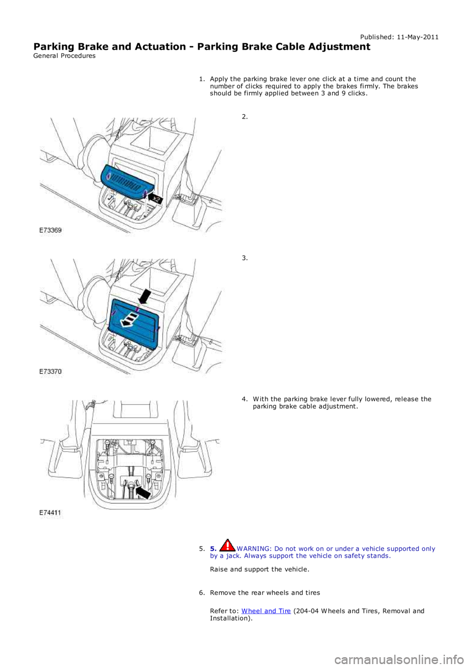
Apply t he parking brake lever one cl ick at a t ime and count t henumber of cl icks required to appl y the brakes fi rml y. The brakess houl d be firmly appl ied between 3 and 9 cli cks .
1.
2.
3.
W it h the parking brake l ever fully lowered, rel eas e t heparking brake cabl e adjus tment .4.
5. W ARNING: Do not work on or under a vehi cle s upported onl yby a jack. Al ways support t he vehi cl e on s afet y s tands .
Rais e and s upport t he vehi cl e.
5.
Remove t he rear wheels and t ires
Refer t o: W heel and Ti re (204-04 W heel s and Tires, Removal andInst all at ion).
6.
Page 456 of 3229
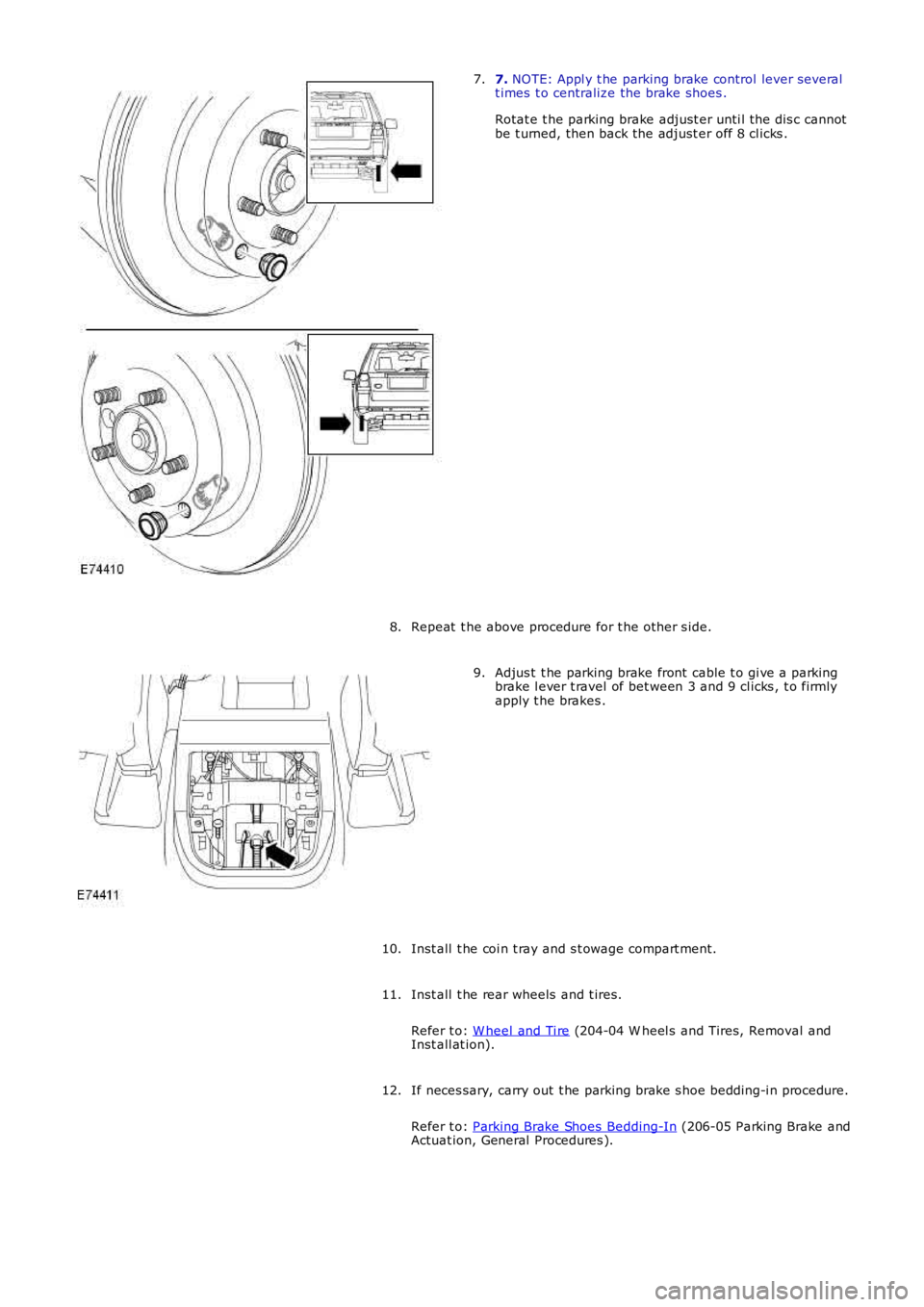
7. NOTE: Appl y t he parking brake control lever severalt imes t o centralize the brake shoes .
Rotat e t he parking brake adjust er unti l t he dis c cannotbe t urned, then back the adjust er off 8 cl icks .
7.
Repeat t he above procedure for t he other s ide.8.
Adjus t t he parking brake front cable t o gi ve a parkingbrake l ever t ravel of bet ween 3 and 9 cl icks , t o firmlyapply t he brakes .
9.
Inst all t he coi n t ray and s t owage compart ment.10.
Inst all t he rear wheels and t ires.
Refer t o: W heel and Ti re (204-04 W heel s and Tires, Removal andInst all at ion).
11.
If neces sary, carry out t he parking brake s hoe bedding-i n procedure.
Refer t o: Parking Brake Shoes Bedding-In (206-05 Parking Brake andActuat ion, General Procedures ).
12.
Page 466 of 3229
6.
7.
Repeat t he above procedure for t he other s ide.8.
Installation
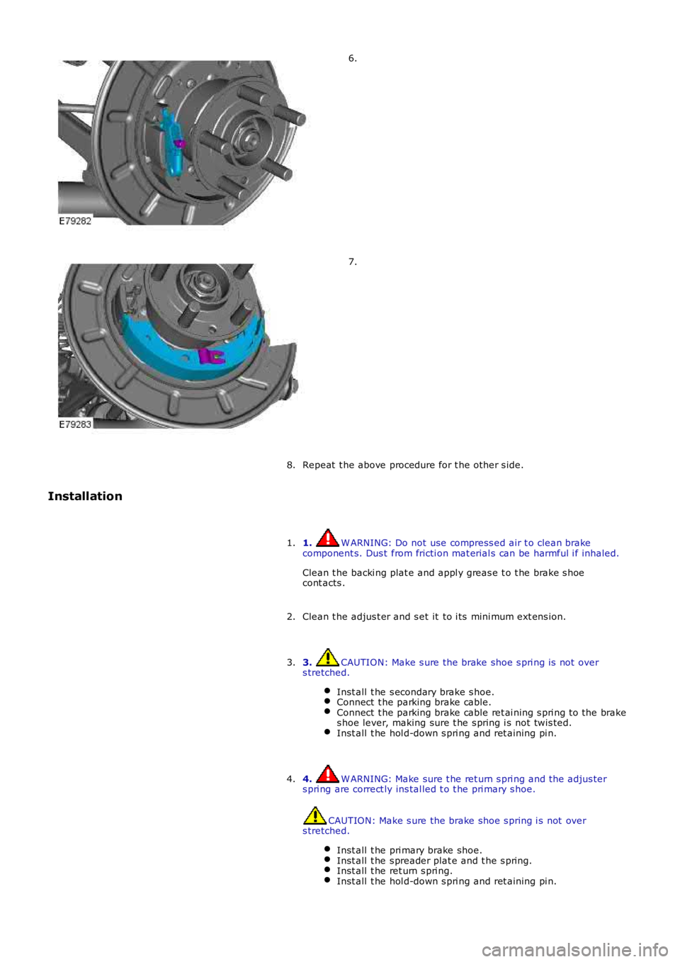
1. W ARNING: Do not use compress ed air t o clean brakecomponent s. Dus t from fricti on mat erial s can be harmful i f inhaled.
Clean t he backi ng plat e and appl y greas e t o t he brake s hoecont acts .
1.
Clean t he adjus t er and s et it to i ts mini mum ext ens ion.2.
3. CAUTION: Make s ure the brake shoe s pri ng is not overs tretched.
Inst all t he s econdary brake s hoe.Connect t he parking brake cable.Connect t he parking brake cable ret ai ning s pri ng t o the brakes hoe lever, making sure t he s pring i s not twis ted.Inst all t he hol d-down s pri ng and ret aining pi n.
3.
4. W ARNING: Make sure t he ret urn s pri ng and t he adjus ters pri ng are correct ly ins tal led t o t he pri mary s hoe.
CAUTION: Make s ure the brake shoe s pring i s not overs tretched.
Inst all t he pri mary brake shoe.Inst all t he s preader plat e and t he s pring.Inst all t he ret urn s pri ng.Inst all t he hol d-down s pri ng and ret aining pi n.
4.
Page 473 of 3229
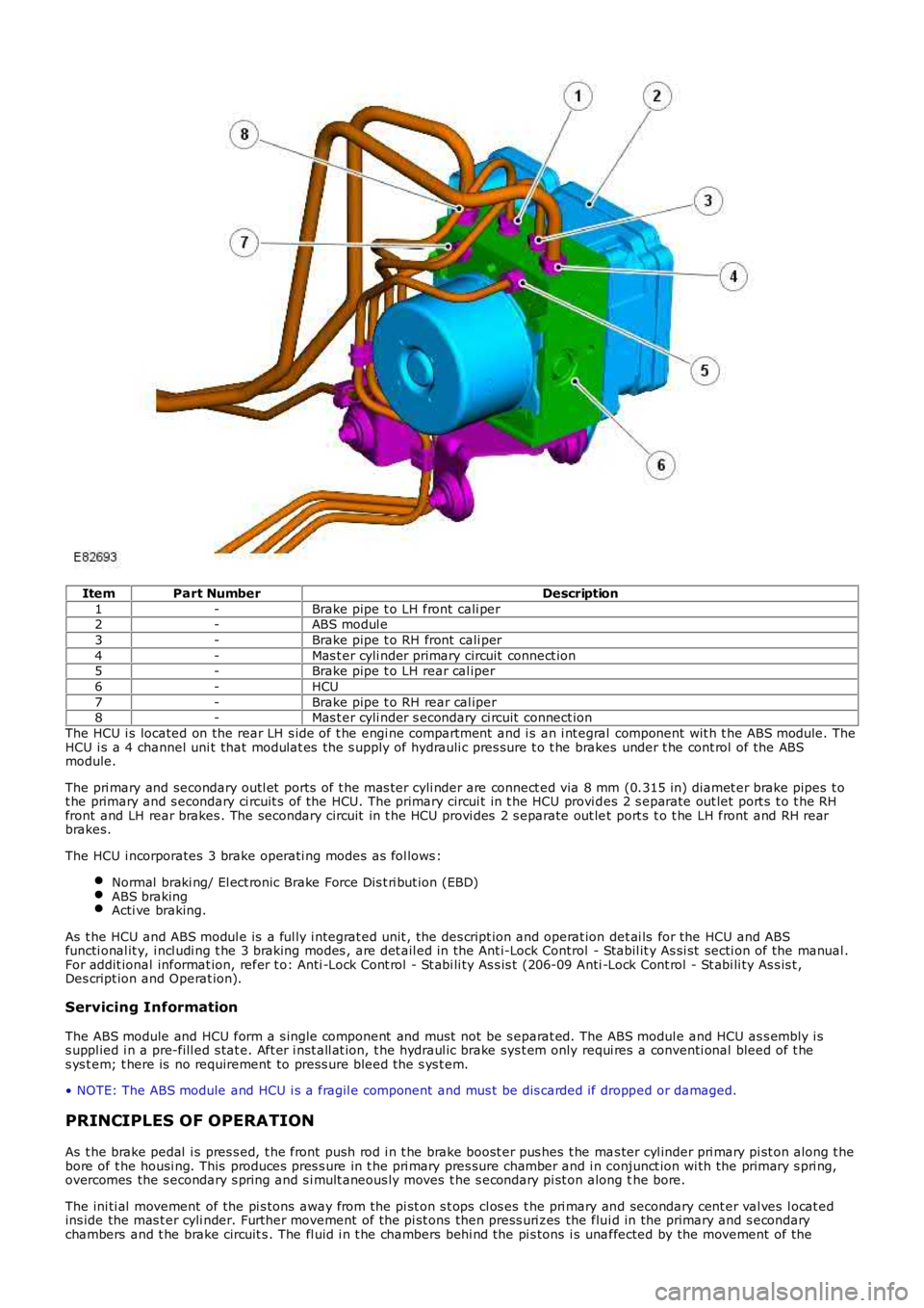
ItemPart NumberDescription
1-Brake pipe t o LH front cali per2-ABS modul e
3-Brake pipe t o RH front cali per
4-Mas t er cyli nder primary circuit connect ion5-Brake pipe t o LH rear cal iper
6-HCU
7-Brake pipe t o RH rear cal iper8-Mas t er cyli nder s econdary ci rcuit connect ion
The HCU i s located on the rear LH s ide of t he engi ne compartment and i s an i nt egral component wit h t he ABS module. TheHCU i s a 4 channel uni t that modulat es the s upply of hydrauli c pres sure t o t he brakes under t he cont rol of the ABSmodule.
The pri mary and secondary outl et ports of t he mas ter cyli nder are connect ed via 8 mm (0.315 in) diamet er brake pipes t ot he primary and s econdary ci rcuit s of the HCU. The primary circui t in t he HCU provi des 2 s eparate out let port s t o t he RHfront and LH rear brakes . The secondary circuit in t he HCU provi des 2 s eparate out let port s t o t he LH front and RH rearbrakes.
The HCU i ncorporates 3 brake operati ng modes as fol lows :
Normal braki ng/ El ect ronic Brake Force Dis t ri but ion (EBD)ABS brakingActi ve braking.
As t he HCU and ABS modul e is a ful ly i ntegrat ed unit , the des cript ion and operat ion det ai ls for the HCU and ABSfuncti onal it y, i ncl udi ng t he 3 braking modes , are det ail ed in the Ant i-Lock Control - Stabil it y As si st secti on of the manual .For addit ional informat ion, refer t o: Anti -Lock Cont rol - St abi li ty As s is t (206-09 Anti -Lock Cont rol - St abi li ty As s is t ,Des cript ion and Operat ion).
Servicing Information
The ABS module and HCU form a s ingle component and must not be s eparat ed. The ABS modul e and HCU as s embly i ss uppl ied i n a pre-fill ed s tat e. Aft er i nst all at ion, t he hydraul ic brake sys t em only requi res a conventi onal bleed of t hes ys t em; t here is no requirement to press ure bleed t he s ys t em.
• NOTE: The ABS module and HCU i s a fragil e component and mus t be dis carded if dropped or damaged.
PRINCIPLES OF OPERATION
As t he brake pedal i s pres s ed, t he front push rod i n t he brake boost er pus hes t he mas ter cyl inder pri mary pi st on along t hebore of t he housi ng. This produces pres s ure in t he pri mary pres sure chamber and i n conjunct ion wi th the primary s pri ng,overcomes the s econdary s pring and s i mult aneous ly moves t he s econdary pi st on along the bore.
The ini ti al movement of the pi s tons away from the pi st on s t ops cl os es t he pri mary and secondary cent er val ves l ocat edins ide the mas t er cyli nder. Further movement of the pi st ons then press uri zes the flui d in the primary and s econdarychambers and t he brake circuit s . The fl uid i n t he chambers behi nd the pi s tons i s unaffected by the movement of the
Page 474 of 3229

pis t ons and will flow unrest ri cted t hrough t he inlet ports , between t he chambers and t he res ervoir.
Pres s urized fluid ent ers the HCU that i s mounted on t he front of the ABS modul e. The HCU t hen modul ates t he s uppl y ofpres s urized fluid to the brakes under cont rol of the ABS modul e.For addit ional informat ion, refer t o: Anti -Lock Cont rol - St abi li ty As s is t (206-09 Anti -Lock Cont rol - St abi li ty As s is t ,Des cript ion and Operat ion).
Page 517 of 3229
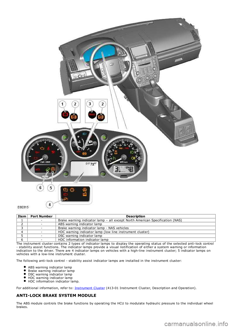
ItemPart NumberDescription
1-Brake warni ng indi cat or l amp – al l except Nort h American Specificati on (NAS)2-ABS warni ng indicator l amp
3-Brake warni ng indi cat or l amp - NAS vehicl es
4-HDC warning i ndi cat or lamp (low li ne ins trument cl ust er)5-DSC warni ng indicat or l amp
6-HDC i nformat ion indicator lamp
The ins t rument clus ter cont ains 2 types of indicator lamps to di s pl ay the operat ing st atus of t he s elected ant i-lock cont rol- s tabil it y as si s t functi ons . The indicat or l amps provide a vis ual not ifi cat ion of ei ther a s yst em warning or i nformat ionindicat ion t o t he dri ver. There are 4 indicat or l amps on vehicles wi th a high-l ine inst rument clus t er; 5 i ndi cat or lamps onvehi cl es wit h a low-line ins trument cl us t er.
The fol lowing ant i-lock cont rol - s t abi li ty as s is t indicat or l amps are ins tall ed in the ins trument cl us t er:
ABS warni ng indicat or l ampBrake warning i ndi cat or lampDSC warni ng indi cat or l ampHDC warning i ndi cat or lampHDC i nformati on indicator l amp.
For addit ional informat ion, refer t o: Ins t rument Clus ter (413-01 Inst rument Cl us t er, Des cript ion and Operat ion).
ANTI-LOCK BRAKE SYSTEM MODULE
The ABS module cont rols the brake funct ions by operat ing t he HCU to modul at e hydrauli c pres s ure t o t he indivi dual wheelbrakes.
Page 518 of 3229
The ABS module is at tached to the HCU and forms an i ntegral component . A 47-pi n connector provides t he electricalint erface bet ween the ABS modul e and t he vehi cl e wi ri ng. The ABS modul e may be i nterrogated us ing the Land Roverapproved diagnos t ic equipment.
HYDRAULIC CONTROL UNIT
The HCU i s a 4 channel uni t that modulat es the s upply of hydrauli c pres sure t o t he brakes , under the control of t he ABSmodule.
The mas ter cylinder pri mary and secondary circuit out let s are connect ed to the HCU pri mary and secondary circuit s .For addit ional informat ion, refer t o: Hydraulic Brake Actuati on (206-06 Hydraulic Brake Act uati on, Des cri pt ion andOperat ion).Each of t he HCU ci rcuit s cont ains t he fol lowing components t o control t he s uppl y of hydraulic press ure to the brakes :
A normally open, s olenoid-operat ed pil ot val ve, t o enabl e acti ve braking.A normally cl osed, s olenoid-operat ed pri ming val ve, t o connect the brake fl uid reservoi r to the dual ci rcuit hydrauli cpump duri ng act ive braki ng.A hydrauli c pump, to generat e hydrauli c pres sure for act ive braking and return brake flui d to the res ervoir.Normal ly open, s ol enoi d-operat ed inlet valves and normal ly cl os ed, s ol enoi d-operat ed out let valves , to modul atet he hydraul ic pres s ure in t he i ndi vi dual brakes .An accumul ator and a relief valve, to allow the fas t rel eas e of pres s ure from t he brakes.Fil ters , t o prot ect t he i nt ernal components from contami nat ion.
The pri mary ci rcuit als o i ncorporates a pres sure s ens or t o provide t he ABS modul e wit h a hydraul ic pres s ure si gnal .
Contact pins on t he HCU mat e wi th cont act s on t he ABS module to provi de t he electrical connect ions from the ABS modul et o the dual circui t hydraul ic pump motor, and t he pres s ure sens or. The s olenoids t hat operat e t he val ves are i nst all edwit hin the ABS modul e.
HCU Schemati c Diagram