2006 LAND ROVER FRELANDER 2 fuses
[x] Cancel search: fusesPage 647 of 3229
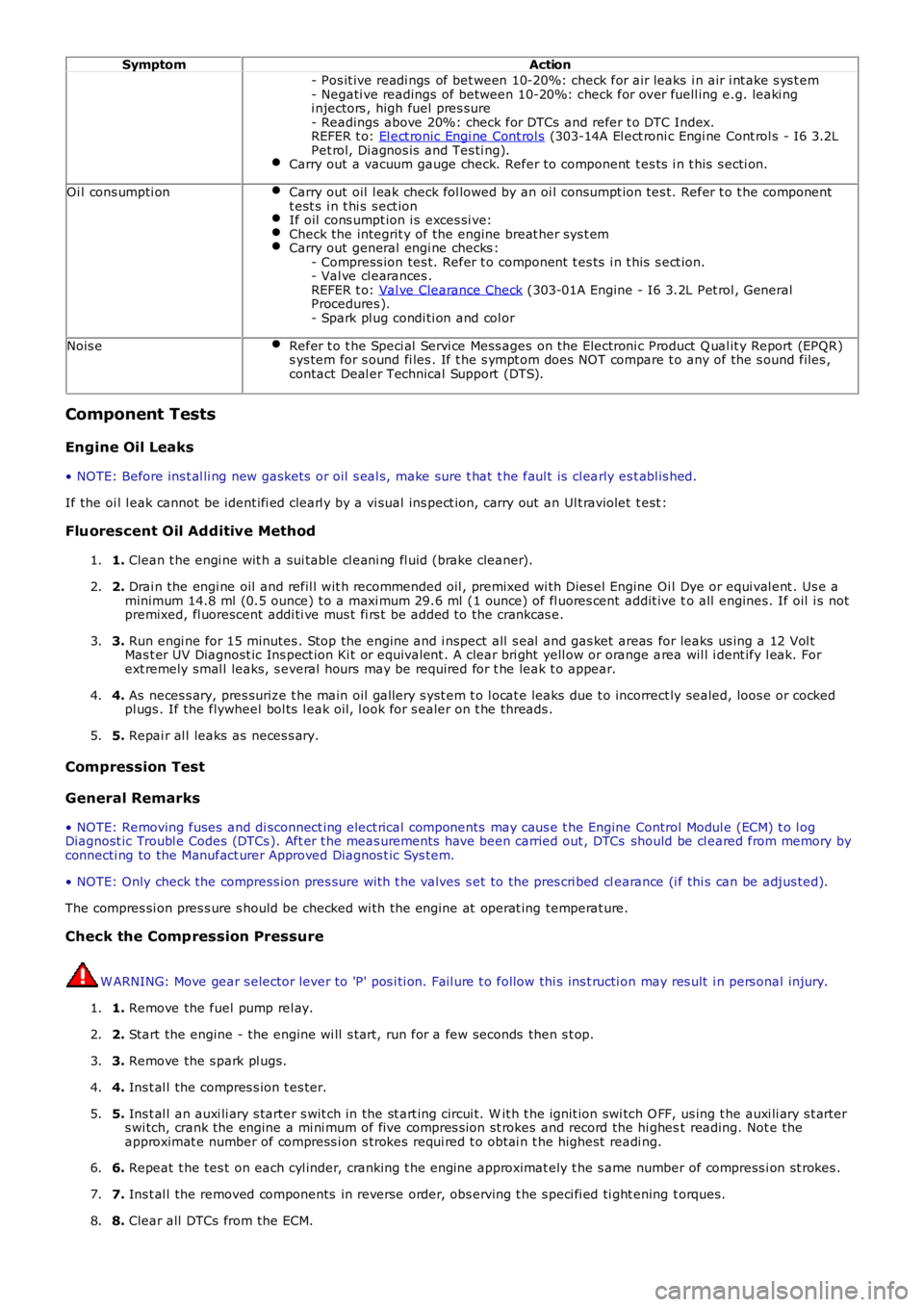
SymptomAction
- Pos it ive readi ngs of bet ween 10-20%: check for air leaks i n air i nt ake s ys t em- Negati ve readings of between 10-20%: check for over fuell ing e.g. leaki ngi njectors , high fuel pres sure- Readings above 20%: check for DTCs and refer t o DTC Index.REFER t o: El ect ronic Engi ne Cont rol s (303-14A El ect roni c Engi ne Cont rol s - I6 3.2LPet rol, Di agnos is and Tes ti ng).Carry out a vacuum gauge check. Refer to component t es ts i n t his s ecti on.
Oi l cons umpti onCarry out oil l eak check fol lowed by an oi l cons umpt ion tes t. Refer t o t he componentt est s i n t hi s s ect ionIf oil cons umpt ion i s exces si ve:Check the integrit y of the engine breat her sys t emCarry out general engi ne checks :- Compress ion tes t. Refer t o component t es ts i n t his s ect ion.- Val ve cl earances .REFER t o: Val ve Clearance Check (303-01A Engine - I6 3.2L Pet rol , GeneralProcedures ).- Spark pl ug condi ti on and col or
Nois eRefer t o t he Speci al Servi ce Mess ages on t he Electroni c Product Q ual it y Report (EPQR)s ys tem for s ound fi les . If t he s ympt om does NOT compare t o any of the s ound files ,contact Deal er Technical Support (DTS).
Component Tests
Engine Oil Leaks
• NOTE: Before ins t al li ng new gasket s or oil s eal s, make sure t hat t he faul t is cl early es t abl is hed.
If the oi l l eak cannot be ident ifi ed clearl y by a vi sual ins pect ion, carry out an Ult raviolet t est :
Fluorescent Oil Additive Method
1. Clean t he engi ne wit h a sui table cl eani ng fl uid (brake cleaner).1.
2. Drai n the engi ne oil and refil l wit h recommended oil , premixed wi th Dies el Engine Oil Dye or equi val ent . Us e aminimum 14.8 ml (0.5 ounce) t o a maxi mum 29.6 ml (1 ounce) of fl uores cent addit ive to all engines. If oil i s notpremixed, fl uorescent addi ti ve mus t fi rs t be added to the crankcas e.
2.
3. Run engi ne for 15 minutes . Stop the engine and i nspect all s eal and gas ket areas for leaks us ing a 12 Vol tMas t er UV Diagnost ic Ins pect ion Ki t or equivalent . A clear bri ght yell ow or orange area wil l i dent ify l eak. Forext remely smal l leaks, s everal hours may be required for t he leak t o appear.
3.
4. As neces s ary, pres surize t he main oil gallery s yst em t o l ocat e leaks due t o incorrect ly sealed, loos e or cockedpl ugs . If the flywheel bol ts l eak oil, l ook for s ealer on t he threads .4.
5. Repai r al l leaks as neces s ary.5.
Compression Test
General Remarks
• NOTE: Removing fuses and di sconnect ing elect rical components may caus e t he Engine Control Modul e (ECM) t o l ogDiagnost ic Troubl e Codes (DTCs ). Aft er t he meas urements have been carried out , DTCs should be cl eared from memory byconnecti ng to the Manufact urer Approved Diagnos t ic Sys tem.
• NOTE: Only check the compress ion pres sure wit h t he valves s et to the pres cri bed clearance (i f thi s can be adjus ted).
The compres si on pres s ure s hould be checked wi th the engine at operat ing temperat ure.
Check the Comp ression Pressure
W ARNING: Move gear s elector lever to 'P' pos i ti on. Fail ure t o follow thi s ins t ructi on may res ult i n pers onal injury.
1. Remove the fuel pump rel ay.1.
2. Start the engine - the engine wi ll s t art, run for a few seconds then s t op.2.
3. Remove the s park pl ugs.3.
4. Ins t al l the compres s ion t es ter.4.
5. Ins t al l an auxi li ary s tarter s wit ch in the st art ing circui t. W it h t he ignit ion swi tch O FF, us ing t he auxi li ary s t arters wi tch, crank the engine a mi ni mum of five compres s ion st rokes and record the hi ghest reading. Not e theapproximat e number of compress i on s trokes requi red t o obt ai n t he highest readi ng.
5.
6. Repeat t he tes t on each cyl inder, cranking t he engine approximat ely t he s ame number of compress i on st rokes .6.
7. Ins t al l the removed components in reverse order, obs erving t he s peci fi ed ti ght ening t orques.7.
8. Clear all DTCs from the ECM.8.
Page 978 of 3229
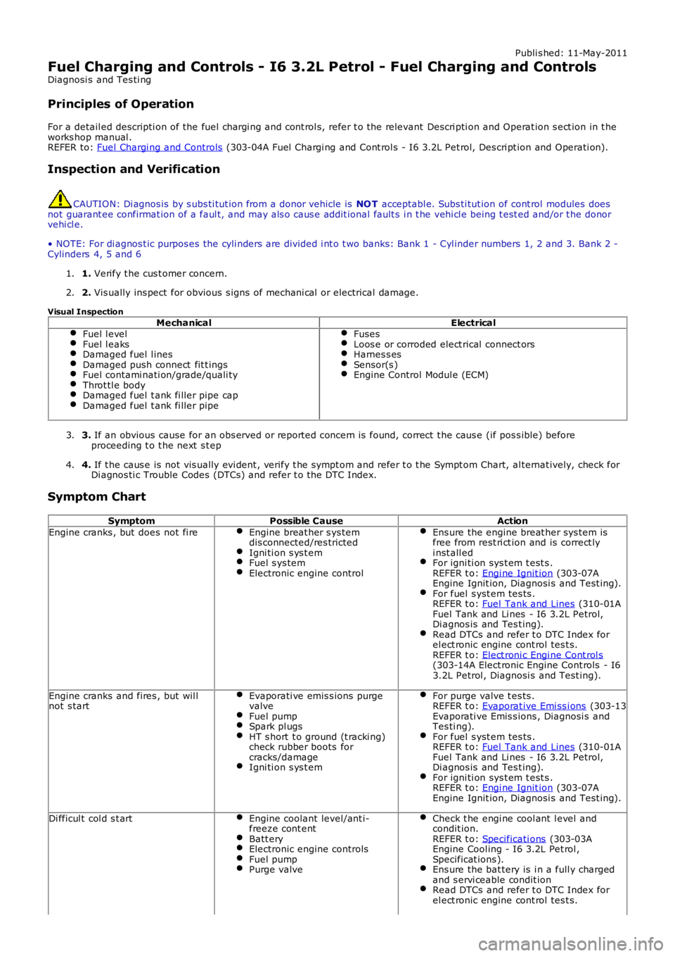
Publi s hed: 11-May-2011
Fuel Charging and Controls - I6 3.2L Petrol - Fuel Charging and Controls
Diagnosi s and Tes ti ng
Principles of Operation
For a detail ed descripti on of the fuel chargi ng and cont rol s, refer t o the relevant Descri pti on and Operat ion s ect ion in t heworks hop manual .REFER to: Fuel Chargi ng and Controls (303-04A Fuel Chargi ng and Cont rol s - I6 3.2L Pet rol, Des cri pt ion and Operati on).
Inspection and Verification
CAUTION: Di agnos is by s ubs ti tut ion from a donor vehicle is NO T acceptabl e. Subs ti tut ion of cont rol modules doesnot guarant ee confirmat ion of a faul t, and may als o caus e addit ional fault s i n t he vehi cl e being t est ed and/or t he donorvehi cl e.
• NOTE: For di agnos t ic purpos es the cyli nders are divided i nt o t wo banks: Bank 1 - Cyl inder numbers 1, 2 and 3. Bank 2 -Cylinders 4, 5 and 6
1. Verify t he cus t omer concern.1.
2. Vis ually ins pect for obvious s igns of mechani cal or electrical damage.2.
Visual Inspection
MechanicalElectricalFuel l evelFuel l eaksDamaged fuel l inesDamaged push connect fit t ingsFuel contami nati on/grade/quali tyThrot tl e bodyDamaged fuel t ank fi ller pipe capDamaged fuel t ank fi ller pipe
FusesLoos e or corroded elect rical connect orsHarnes s esSensor(s )Engine Control Modul e (ECM)
3. If an obvious cause for an obs erved or report ed concern is found, correct t he caus e (if pos s ible) beforeproceeding t o t he next s t ep3.
4. If t he caus e is not vis ually evi dent , verify t he sympt om and refer t o t he Sympt om Chart, al ternat ively, check forDi agnos ti c Trouble Codes (DTCs) and refer t o t he DTC Index.4.
Symptom Chart
SymptomPossible CauseAction
Engine cranks , but does not fi reEngine breat her s ys temdis connected/res trictedIgni ti on s ys t emFuel s ys temElectronic engine control
Ens ure the engine breat her sys tem isfree from rest ri ct ion and is correct lyi nst all edFor igni ti on sys t em t est s .REFER t o: Engi ne Ignit ion (303-07AEngine Ignit ion, Diagnosi s and Test ing).For fuel s yst em tes ts .REFER t o: Fuel Tank and Lines (310-01AFuel Tank and Li nes - I6 3.2L Petrol,Di agnos is and Tes t ing).Read DTCs and refer t o DTC Index forel ect ronic engine cont rol tes t s.REFER t o: Elect roni c Engi ne Cont rol s(303-14A Elect ronic Engine Cont rols - I63.2L Petrol , Diagnosi s and Test ing).
Engine cranks and fires , but wil lnot s tartEvaporati ve emis s ions purgevalveFuel pumpSpark pl ugsHT s hort t o ground (t racki ng)check rubber boots forcracks/damageIgni ti on s ys t em
For purge valve t es ts .REFER t o: Evaporat ive Emi ss i ons (303-13Evaporati ve Emis s ions , Diagnosi s andTes ti ng).For fuel s yst em tes ts .REFER t o: Fuel Tank and Lines (310-01AFuel Tank and Li nes - I6 3.2L Petrol,Di agnos is and Tes t ing).For igni ti on sys t em t est s .REFER t o: Engi ne Ignit ion (303-07AEngine Ignit ion, Diagnosi s and Test ing).
Di fficul t col d s t artEngine coolant level/ant i-freeze cont entBatt eryElectronic engine controlsFuel pumpPurge valve
Check t he engi ne cool ant l evel andcondit ion.REFER t o: Specificati ons (303-03AEngine Cool ing - I6 3.2L Pet rol ,Specificat ions ).Ens ure the bat tery is i n a full y chargedand s ervi ceable condit ionRead DTCs and refer t o DTC Index forel ect ronic engine cont rol tes t s.
Page 1202 of 3229
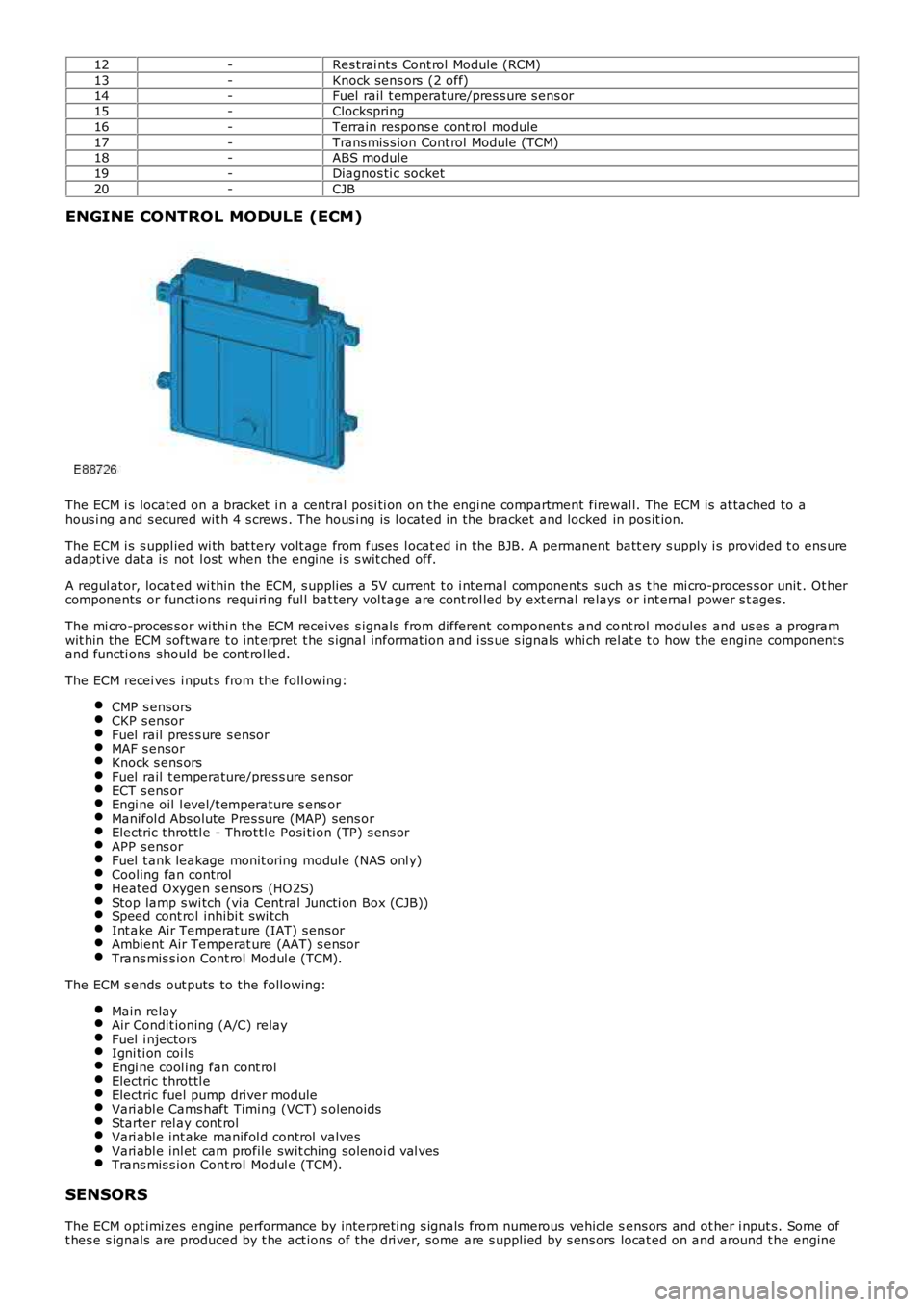
12-Res trai nts Cont rol Module (RCM)
13-Knock sens ors (2 off)
14-Fuel rail t emperature/pres s ure s ens or15-Clockspring
16-Terrain respons e cont rol module
17-Trans mis s ion Cont rol Module (TCM)18-ABS module
19-Diagnos ti c socket
20-CJB
ENGINE CONTROL MODULE (ECM)
The ECM i s located on a bracket i n a central pos i ti on on the engi ne compartment firewal l. The ECM is at tached to ahous i ng and s ecured wit h 4 s crews . The hous i ng is l ocat ed in the bracket and locked in pos it ion.
The ECM i s s uppl ied wi th bat tery volt age from fuses l ocat ed in the BJB. A permanent batt ery s upply i s provided t o ens ureadapt ive dat a is not l ost when the engine i s s wit ched off.
A regul ator, locat ed wi thin the ECM, s upplies a 5V current t o i nt ernal components such as t he mi cro-proces s or unit . Ot hercomponents or funct ions requi ri ng ful l bat tery vol tage are cont rol led by ext ernal relays or int ernal power s t ages .
The mi cro-proces sor wi thi n the ECM receives s ignals from different component s and cont rol modules and us es a programwit hin the ECM software t o int erpret t he s ignal informat ion and i ss ue s ignals whi ch rel at e t o how the engine component sand functi ons should be cont rol led.
The ECM recei ves i nput s from the foll owing:
CMP s ensorsCKP s ensorFuel rail pres s ure s ensorMAF s ensorKnock s ens orsFuel rail t emperature/pres s ure s ensorECT s ens orEngi ne oil l evel/t emperature s ens orManifol d Abs olute Pres sure (MAP) sens orElectric t hrot tl e - Throt tl e Posi ti on (TP) s ens orAPP s ens orFuel t ank leakage monit oring modul e (NAS onl y)Cooling fan controlHeated Oxygen s ens ors (HO2S)Stop lamp s wi tch (via Central Juncti on Box (CJB))Speed cont rol inhibi t swi tchInt ake Air Temperat ure (IAT) s ens orAmbient Air Temperat ure (AAT) s ens orTrans mis s ion Cont rol Modul e (TCM).
The ECM s ends out puts to t he followi ng:
Main relayAir Condit ioning (A/C) relayFuel i njectorsIgni ti on coi lsEngi ne cool ing fan cont rolElectric t hrot tl eElectric fuel pump driver moduleVari abl e Cams haft Timing (VCT) s olenoidsStarter rel ay cont rolVari abl e int ake manifol d control valvesVari abl e inl et cam profile swit ching sol enoi d val vesTrans mis s ion Cont rol Modul e (TCM).
SENSORS
The ECM opt imi zes engine performance by interpreti ng s ignals from numerous vehicle sens ors and ot her i nput s. Some oft hes e s ignals are produced by t he act ions of t he dri ver, some are s uppli ed by s ens ors locat ed on and around t he engine
Page 1556 of 3229
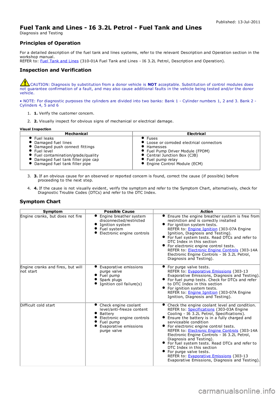
Publi shed: 13-Jul-2011
Fuel Tank and Lines - I6 3.2L Petrol - Fuel Tank and Lines
Diagnosi s and Tes ti ng
Principles of Operation
For a detail ed descripti on of the fuel tank and l ines s ys t ems , refer t o t he rel evant Des cript ion and Operat ion s ecti on in theworks hop manual .REFER to: Fuel Tank and Lines (310-01A Fuel Tank and Lines - I6 3.2L Pet rol , Descri pti on and Operat ion).
Inspection and Verification
CAUTION: Di agnos is by s ubs ti tut ion from a donor vehicle is NO T acceptabl e. Subs ti tut ion of cont rol modules doesnot guarant ee confirmat ion of a faul t, and may als o caus e addit ional fault s i n t he vehi cl e being t est ed and/or t he donorvehi cl e.
• NOTE: For di agnos t ic purpos es the cyli nders are divided i nt o t wo banks: Bank 1 - Cyl inder numbers 1, 2 and 3. Bank 2 -Cylinders 4, 5 and 6
1. Verify t he cus t omer concern.1.
2. Vis ually ins pect for obvious s igns of mechani cal or electrical damage.2.
Visual Inspection
MechanicalElectricalFuel l eaksDamaged fuel l inesDamaged push connect fit t ingsFuel l evelFuel contami nati on/grade/quali tyDamaged fuel t ank fi ller pipe capDamaged fuel t ank fi ller pipe
FusesLoos e or corroded elect rical connect orsHarnes s esFuel Pump Dri ver Module (FPDM)Central Junct ion Box (CJB)Fuel pump relayEngine Control Modul e (ECM)
3. If an obvious cause for an obs erved or report ed concern is found, correct t he caus e (if pos s ible) beforeproceeding t o t he next s t ep.3.
4. If t he caus e is not vis ually evi dent , verify t he sympt om and refer t o t he Sympt om Chart, al ternat ively, check forDi agnos ti c Trouble Codes (DTCs) and refer t o t he DTC Index.4.
Symptom Chart
SymptomPossible CauseAction
Engine cranks , but does not fi reEngine breat her sys temdi sconnect ed/res trict edIgnit ion s yst emFuel sys temEl ect ronic engine controls
Ens ure t he engi ne breat her s ys tem is free fromres t ri ct ion and is correct ly i nst all edFor ignit ion s ys tem tes t s.REFER to: Engine Ignit ion (303-07A EngineIgni ti on, Di agnos is and Tes t ing).For fuel s ys t em t est s . Read DTCs and refer t oDTC Index in t his secti onFor elect roni c engi ne cont rol t es t s .REFER to: El ect ronic Engine Cont rols (303-14AElectronic Engine Controls - I6 3.2L Petrol ,Di agnos is and Tes ti ng).
Engine cranks and fires , but wil lnot s tartEvaporati ve emis s ionspurge val veFuel pumpSpark pl ugsIgnit ion coil fai lure(s )
For purge valve t est s .REFER to: Evaporati ve Emis s ions (303-13Evaporati ve Emis s ions, Di agnos is and Tes t ing).For fuel pump t es t s . Check for DTCs and refert o DTC Index in t his s ecti onFor ignit ion s ys tem tes t s.REFER to: Engine Ignit ion (303-07A EngineIgni ti on, Di agnos is and Tes t ing).
Di fficul t col d s t artCheck engi ne cool antl evel /anti -freeze cont entBat teryEl ect ronic engine controlsFuel pumpEvaporati ve emis s ionspurge val ve
Check the engine coolant level and condit ion.REFER to: Specifi cat ions (303-03A EngineCooli ng - I6 3.2L Petrol, Speci fi cat ions ).Ens ure t he batt ery i s in a ful ly charged ands erviceable condi ti onFor elect roni c engi ne cont rol t es t s .REFER to: El ect ronic Engine Cont rols (303-14AElectronic Engine Controls - I6 3.2L Petrol ,Di agnos is and Tes ti ng).For fuel s ys t em t est s . Read DTCs and refer t oDTC Index in t his secti onFor purge valve t est s .REFER to: Evaporati ve Emis s ions (303-13Evaporati ve Emis s ions, Di agnos is and Tes t ing).
Page 1591 of 3229
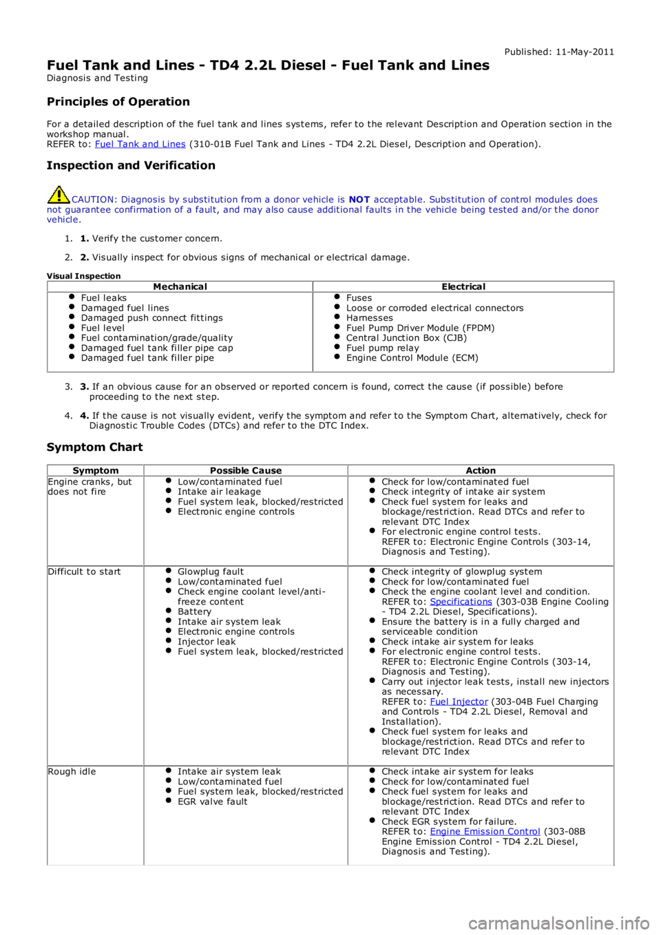
Publi s hed: 11-May-2011
Fuel Tank and Lines - TD4 2.2L Diesel - Fuel Tank and Lines
Diagnosi s and Tes ti ng
Principles of Operation
For a detail ed descripti on of the fuel tank and l ines s ys t ems , refer t o t he rel evant Des cript ion and Operat ion s ecti on in the
works hop manual .
REFER to: Fuel Tank and Lines (310-01B Fuel Tank and Lines - TD4 2.2L Dies el, Des cript ion and Operat ion).
Inspection and Verification CAUTION: Di agnos is by s ubs ti tut ion from a donor vehicle is
NO T acceptabl e. Subs ti tut ion of cont rol modules does
not guarant ee confirmat ion of a faul t, and may als o caus e addit ional fault s i n t he v ehi cl e being t est ed and/or t he donor
vehi cl e.
1. Verify t he cus t omer concern.
1.
2. Vis ually ins pect for obvious s igns of mechani cal or electrical damage.
2.
Visual Inspection Mechanical Electrical
Fuel l eaks Damaged fuel l ines
Damaged push connect fit t ings
Fuel l evel
Fuel contami nati on/grade/quali ty
Damaged fuel t ank fi ller pipe cap
Damaged fuel t ank fi ller pipe Fuses
Loos e or corroded elect rical connect ors
Harnes s es
Fuel Pump Dri ver Module (FPDM)
Central Junct ion Box (CJB)
Fuel pump relay
Engine Control Modul e (ECM)
3.
If an obvious cause for an obs erved or report ed concern is found, correct t he caus e (if pos s ible) before
proceeding t o t he next s t ep.
3.
4. If t he caus e is not vis ually evi dent , verify t he sympt om and refer t o t he Sympt om Ch art, al ternat ively, check for
Di agnos ti c Trouble Codes (DTCs) and refer t o t he DTC Index.
4.
Symptom Chart Symptom Possible Cause Action
Engine cranks , but
does not fi re Low/contaminated fuel Intake air l eakage
Fuel sys tem leak, blocked/res tricted
El ect ronic engine controls Check for l ow/contami nat ed fuel
Check int egrit y of i nt ake air s yst em
Check fuel s yst em for leaks and
bl ockage/res t ri ct ion. Read DTCs and refer to
relevant DTC Index For electronic engine control t es ts .
REFER t o: Electroni c Engi ne Control s (303-14,
Diagnos is and Tes t ing). Di fficul t t o s tart
Gl owpl ug faul t Low/contaminated fuel
Check engi ne cool ant l evel /anti -
freeze cont ent Bat tery
Intake air s ys tem leak
El ect ronic engine controls
Injector l eak
Fuel sys tem leak, blocked/res tricted Check int egrit y of glowpl ug sys t em
Check for l ow/contami nat ed fuel
Check t he engi ne cool ant l evel and condi ti on.
REFER t o: Specificati ons (303-03B Engine Cool ing
- TD4 2.2L Di es el, Specificat ions ). Ens ure the bat tery is i n a full y charged and
servi ceable condit ion Check int ake air s yst em for leaks
For electronic engine control t es ts .
REFER t o: Electroni c Engi ne Control s (303-14,
Diagnos is and Tes t ing). Carry out i njector leak t est s , ins tal l new inject ors
as neces sary.
REFER t o: Fuel Injector (303-04B Fuel Charging
and Cont rols - TD4 2.2L Di esel , Removal and
Ins tal lati on). Check fuel s yst em for leaks and
bl ockage/res t ri ct ion. Read DTCs and refer to
relevant DTC Index Rough idl e
Intake air s ys tem leak Low/contaminated fuel
Fuel sys tem leak, blocked/res tricted
EGR val ve fault Check int ake air s yst em for leaks
Check for l ow/contami nat ed fuel
Check fuel s yst em for leaks and
bl ockage/res t ri ct ion. Read DTCs and refer to
relevant DTC Index Check EGR s ys tem for fai lure.
REFER t o: Engi ne Emis s ion Cont rol (303-08B
Engine Emis s ion Control - TD4 2.2L Di esel ,
Diagnos is and Tes t ing).
Page 1830 of 3229
• NOTE: The fus i bl e l inks are mount ed on t he inboard s i de of the BJB behind a series of removable covers .
The CJB is mount ed behind t he glovebox and recei ves it s main power s uppl y from the BJB. In addi ti on to cont aining bl adefus es , the CJB i s t he main controll er for a number of vehicle s ys t ems. Thes e functi ons are out li ned in t he rel evant s ect ionsof thi s manual .
The AJB is locat ed beneat h t he luggage compartment carpet , adjacent t he spare wheel wel l. The AJB i s a modular des ign,and compris es up t o 3 individual elements depending on vehicle specificati on. The AJB cont ains bl ade and J-cas e fuses ,and rel ays to di st ribute el ect ri cal power to sys t ems used at the rear of t he vehi cle. The AJB receives it s mai n power s upplyfrom the BJB.
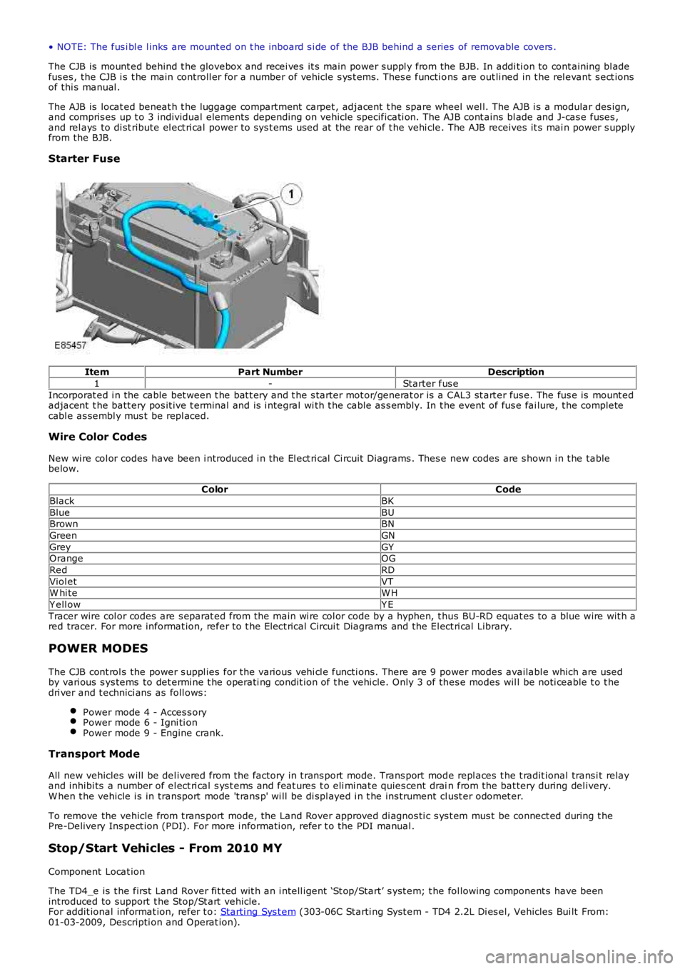
Starter Fuse
ItemPart NumberDescription
1-Starter fus e
Incorporat ed i n the cable bet ween t he bat t ery and t he s tarter mot or/generat or is a CAL3 st art er fus e. The fus e is mount edadjacent t he batt ery pos it ive t erminal and is i ntegral wi th t he cable as s embly. In the event of fus e fai lure, t he completecabl e as sembl y mus t be repl aced.
Wire Color Codes
New wi re col or codes have been i ntroduced i n the El ect ri cal Ci rcuit Di agrams . Thes e new codes are s hown i n t he tablebelow.
ColorCode
BlackBK
BlueBUBrownBN
GreenGN
GreyGYOrangeOG
RedRD
Viol etVTW hi teW H
Y ell owY E
Tracer wire col or codes are s eparat ed from the main wi re col or code by a hyphen, t hus BU-RD equat es to a blue wire wit h ared tracer. For more informat ion, refer to t he Elect rical Circui t Diagrams and the El ect ri cal Library.
POWER MODES
The CJB cont rol s the power s uppl ies for the vari ous vehi cl e functi ons. There are 9 power modes availabl e which are usedby vari ous s ys tems to det ermi ne t he operati ng condit ion of t he vehi cle. Only 3 of thes e modes wil l be noti ceable t o t hedri ver and t echnici ans as foll ows:
Power mode 4 - Acces s oryPower mode 6 - Igni ti onPower mode 9 - Engine crank.
Transport Mode
All new vehicles will be del ivered from the factory in t rans port mode. Trans port mode repl aces t he t radit ional trans i t relayand inhibi ts a number of el ect ri cal s ys t ems and feat ures t o eli mi nat e quies cent drain from the bat tery during del ivery.W hen t he vehicle i s in transport mode 't rans p' wi ll be di spl ayed i n t he ins trument cl ust er odomet er.
To remove the vehicle from t rans port mode, the Land Rover approved di agnos ti c s ys t em mus t be connect ed during t hePre-Delivery Ins pect ion (PDI). For more i nformati on, refer t o the PDI manual .
Stop/Start Vehicles - From 2010 MY
Component Locat ion
The TD4_e is t he first Land Rover fit t ed wit h an i ntell igent ‘St op/Start’ s yst em; t he fol lowing component s have beenint roduced to support t he Stop/St art vehicle.For addit ional informat ion, refer t o: Starti ng Sys t em (303-06C Starti ng Syst em - TD4 2.2L Di es el, Vehicles Bui lt From:01-03-2009, Descripti on and Operat ion).
Page 1833 of 3229
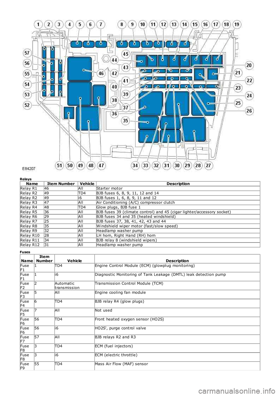
Relays
NameItem NumberVehicleDescriptionRelay R146Al lStarter mot or
Relay R249TD4BJB fus es 6, 8, 9, 11, 12 and 14
Relay R249i 6BJB fus es 1, 6, 8, 9, 11 and 12Relay R347Al lAir Condit ioning (A/C) compres s or cl utch
Relay R448TD4Glow plugs , BJB fus e 1
Relay R536Al lBJB fus es 39 (climat e control) and 45 (cigar light er/access ory socket)Relay R629Al lBJB fus es 34 and 35 (heated wi nds hiel d)
Relay R725Al lBJB fus es 37, 38, 41, 42, 43 and 44
Relay R835Al lW i ndshi el d wi per mot or (fast /sl ow s peed)Relay R932Al lHeadlamp was her pump
Relay R1028Al lLH horn, Ri ght Hand (RH) horn
Relay R1134Al lBJB rel ay 8 (winds hi eld wipers )Relay R1231Al lHeadlamp was her pump
Fuses
NameItemNumberVehicleDescription
FuseF11TD4Engine Cont rol Module (ECM) (gl owpl ug monit ori ng)
FuseF11i 6Diagnos t ic Monit ori ng of Tank Leakage (DMTL) leak det ect ion pump
FuseF22Automat ict rans mis s ionTransmis si on Control Module (TCM)
FuseF35AllEngine cooli ng fan modul e
FuseF46TD4BJB relay R4 (glow plugs)
FuseF57AllNot us ed
FuseF656TD4Front heat ed oxygen s ensor (HO2S)
FuseF656i 6HO2S', purge cont rol valve
FuseF757AllBJB relays R2 and R3
FuseF83TD4ECM (fuel injectors)
FuseF83i 6ECM (el ect ri c thrott le)
FuseF955TD4Mas s Ai r Flow (MAF) s ens or
Page 1835 of 3229
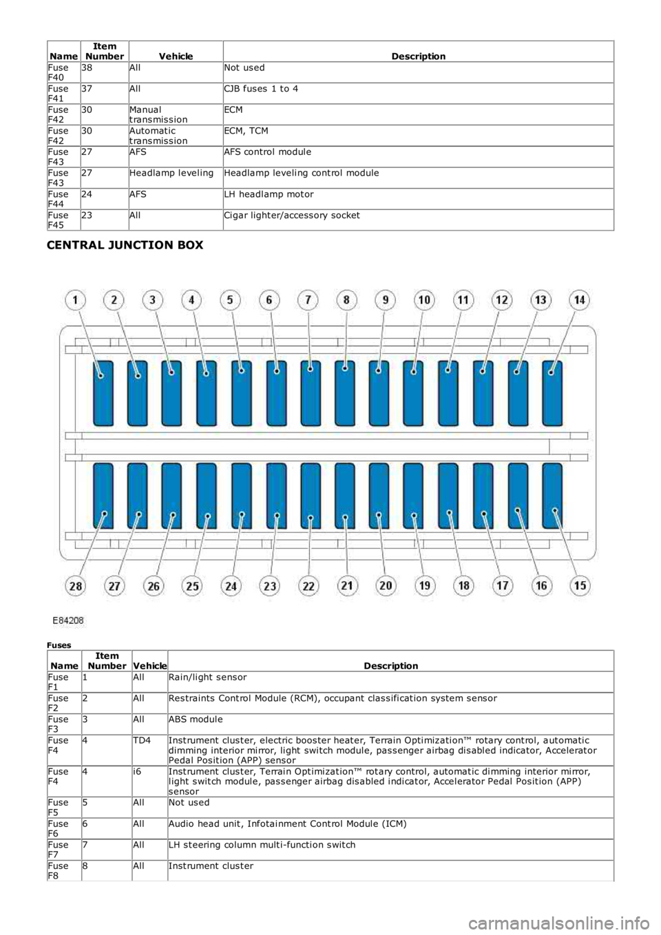
NameItemNumberVehicleDescription
FuseF4038AllNot us ed
FuseF4137AllCJB fus es 1 t o 4
FuseF4230Manualt rans mis s ionECM
FuseF4230Automat ict rans mis s ionECM, TCM
FuseF4327AFSAFS control modul e
FuseF4327Headlamp l evel ingHeadlamp leveli ng cont rol module
FuseF4424AFSLH headl amp mot or
FuseF4523AllCi gar light er/access ory socket
CENTRAL JUNCTION BOX
Fuses
NameItemNumberVehicleDescription
FuseF11AllRain/li ght s ens or
FuseF22AllRes traints Cont rol Module (RCM), occupant clas s ifi cat ion sys tem s ens or
FuseF33AllABS modul e
FuseF44TD4Inst rument clus t er, electric boos ter heat er, Terrain Opti mizati on™ rotary cont rol, aut omati cdimming interior mi rror, li ght swi tch modul e, pas s enger airbag di s abl ed indicator, Accelerat orPedal Pos it ion (APP) sens or
FuseF44i6Inst rument clus t er, Terrai n Opt imi zat ion™ rot ary control, automat ic di mming interior mi rror,l ight s wit ch modul e, pas s enger airbag dis abled i ndi cat or, Accel erator Pedal Pos it ion (APP)s ensorFuseF55AllNot us ed
FuseF66AllAudio head unit , Infotai nment Cont rol Modul e (ICM)
FuseF77AllLH s t eering column mult i-functi on s wit ch
FuseF88AllInst rument clus t er