2006 LAND ROVER FRELANDER 2 fuses
[x] Cancel search: fusesPage 1837 of 3229
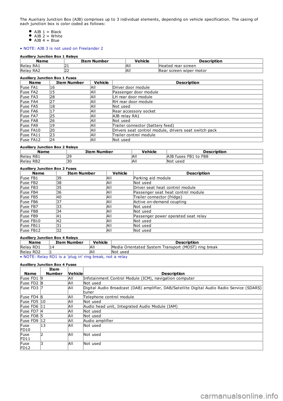
The Auxi li ary Junct ion Box (AJB) compris es up t o 3 i ndi vi dual el ement s , depending on vehicle specificati on. The casi ng ofeach junct ion box is color coded as foll ows:
AJB 1 = BlackAJB 2 = W hit eAJB 4 = Blue
• NOTE: AJB 3 i s not used on Freelander 2
Auxiliary Junction Box 1 Relays
NameItem NumberVehicleDescriptionRelay RA121AllHeat ed rear s creen
Relay RA222AllRear s creen wiper mot or
Auxiliary Junction Box 1 Fuses
NameItem NumberVehicleDescription
Fuse FA116AllDri ver door moduleFuse FA215AllPass enger door module
Fuse FA328AllLH rear door module
Fuse FA427AllRH rear door moduleFuse FA518AllNot used
Fuse FA617AllRear acces s ory socket
Fuse FA725AllAJB rel ay RA1Fuse FA826AllNot used
Fuse FA919AllTrail er connect or (bat tery feed)
Fuse FA1020AllDri vers s eat cont rol module, dri vers s eat s wi tch packFuse FA1123AllTrail er cont rol module
Fuse FA1224AllNot used
Auxiliary Junction Box 2 Relays
NameItem NumberVehicleDescriptionRelay RB129AllAJB fuses FB1 t o FB8
Relay RB230AllNot us ed
Auxiliary Junction Box 2 Fuses
NameItem NumberVehicleDescription
Fuse FB139Al lParki ng aid moduleFuse FB238Al lNot us ed
Fuse FB335Al lDriver seat heat cont rol module
Fuse FB436Al lPas senger seat heat cont rol moduleFuse FB540Al lTrai ler connector (fridge)
Fuse FB637Al lActi ve on-demand coupl ing
Fuse FB733Al lNot us edFuse FB834Al lNot us ed
Fuse FB941Al lPas senger power operat ed s eat relay
Fuse FB1042Al lNot us edFuse FB1131Al lNot us ed
Fuse FB1232Al lNot us ed
Auxiliary Junction Box 4 Relays
NameItem NumberVehicleDescriptionRelay RD114AllMedi a Orientat ed Syst em Transport (MOST) ring break
Relay RD21AllNot us ed
• NOTE: Relay RD1 is a 'plug i n' ring break, not a relay
Auxiliary Junction Box 4 Fuses
NameItemNumberVehicleDescriptionFuse FD19Al lInfotainment Control Modul e (ICM), navi gat ion computer
Fuse FD28Al lNot used
Fuse FD37Al lDigit al Audi o Broadcast (DAB) ampli fi er, DAB/Sat el li te Digit al Audi o Radi o Servi ce (SDARS)tuner
Fuse FD46Al lTel ephone control modul eFuse FD510Al lNot used
Fuse FD611Al lAudi o head unit , Int egrated Audio Modul e (IAM)
Fuse FD74Al lNot usedFuse FD85Al lNot used
Fuse FD912Al lAudi o ampli fi er
FuseFD1013Al lNot used
FuseFD112Al lNot used
FuseFD123Al lNot used
Page 1960 of 3229
Publi s hed: 11-May-2011
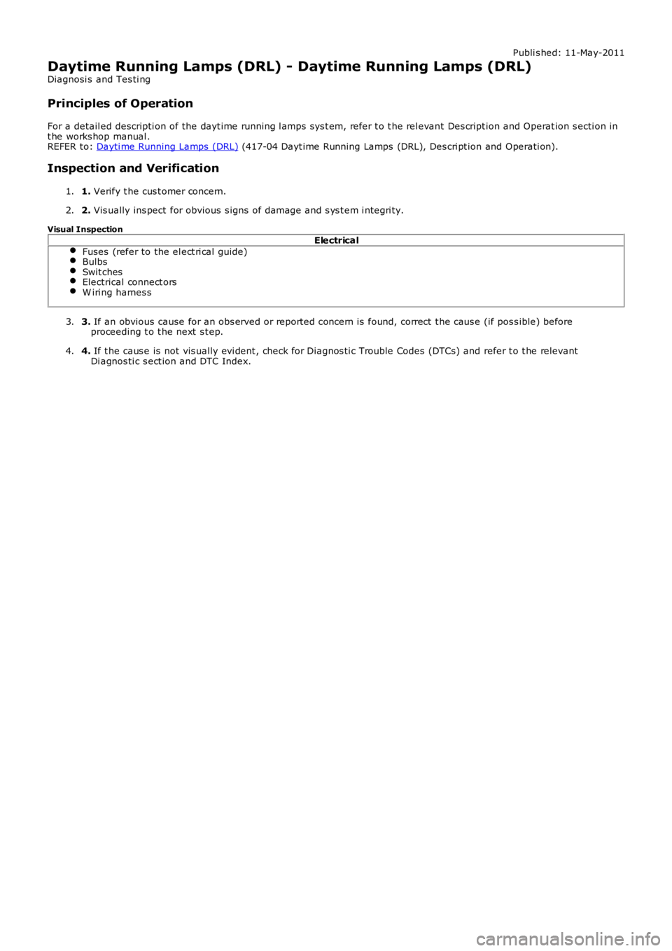
Daytime Running Lamps (DRL) - Daytime Running Lamps (DRL)
Diagnosi s and Tes ti ng
Principles of Operation
For a detail ed descripti on of the dayt ime running l amps sys t em, refer t o t he rel evant Des cript ion and Operat ion s ecti on int he works hop manual .REFER to: Dayti me Running Lamps (DRL) (417-04 Dayt ime Running Lamps (DRL), Des cri pt ion and Operati on).
Inspection and Verification
1. Verify t he cus t omer concern.1.
2. Vis ually ins pect for obvious s igns of damage and s ys t em i ntegri ty.2.
Visual Inspection
Electrical
Fuses (refer to the el ect ri cal guide)BulbsSwit chesElectrical connect orsW iri ng harnes s
3. If an obvious cause for an obs erved or report ed concern is found, correct t he caus e (if pos s ible) beforeproceeding t o t he next s t ep.3.
4. If t he caus e is not vis ually evi dent , check for Di agnos ti c Trouble Codes (DTCs) and refer t o t he relevantDi agnos ti c s ect ion and DTC Index.4.
Page 1969 of 3229
Publi shed: 06-Jul-2011
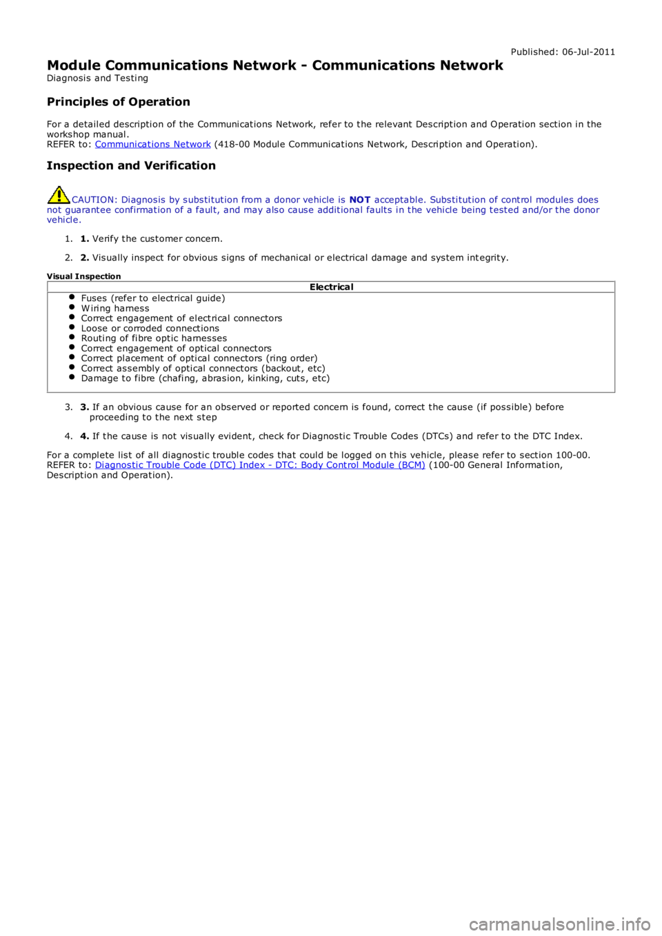
Module Communications Network - Communications Network
Diagnosi s and Tes ti ng
Principles of Operation
For a detail ed descripti on of the Communi cat ions Net work, refer to t he relevant Des cript ion and O perati on sect ion i n theworks hop manual .REFER to: Communi cat ions Network (418-00 Modul e Communi cat ions Network, Des cri pti on and Operati on).
Inspection and Verification
CAUTION: Di agnos is by s ubs ti tut ion from a donor vehicle is NO T acceptabl e. Subs ti tut ion of cont rol modules doesnot guarant ee confirmat ion of a faul t, and may als o caus e addit ional fault s i n t he vehi cl e being t est ed and/or t he donorvehi cl e.
1. Verify t he cus t omer concern.1.
2. Vis ually ins pect for obvious s igns of mechani cal or electrical damage and sys tem integrit y.2.
Visual InspectionElectrical
Fuses (refer to elect rical guide)W iri ng harnes sCorrect engagement of el ect ri cal connectorsLoose or corroded connect ionsRouti ng of fi bre opt ic harnes sesCorrect engagement of opt ical connect orsCorrect pl acement of opti cal connectors (ring order)Correct as s embly of opti cal connect ors (backout , etc)Damage t o fibre (chafi ng, abras ion, kinking, cut s , etc)
3. If an obvious cause for an obs erved or report ed concern is found, correct t he caus e (if pos s ible) beforeproceeding t o t he next s t ep3.
4. If t he caus e is not vis ually evi dent , check for Di agnos ti c Trouble Codes (DTCs) and refer t o t he DTC Index.4.
For a compl ete lis t of all di agnos ti c troubl e codes that coul d be l ogged on t his vehicle, pleas e refer to s ect ion 100-00.REFER to: Di agnos ti c Trouble Code (DTC) Index - DTC: Body Cont rol Module (BCM) (100-00 General Informat ion,Des cript ion and Operat ion).
Page 2189 of 3229
Publi shed: 26-Jul-2011
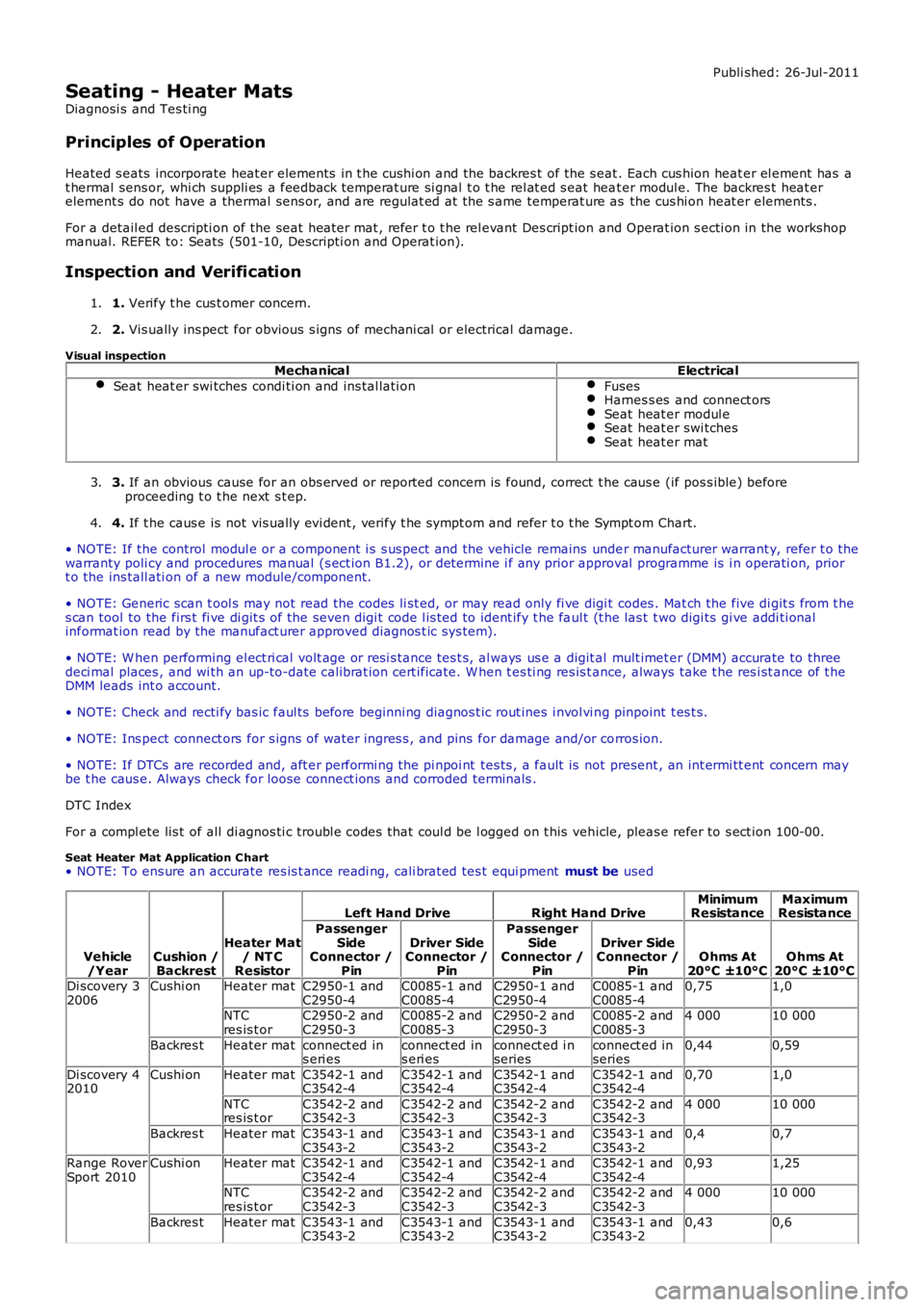
Seating - Heater Mats
Diagnosi s and Tes ti ng
Principles of Operation
Heated s eats incorporate heat er elements in t he cushi on and the backres t of the s eat. Each cus hion heat er el ement has at hermal sens or, whi ch suppli es a feedback temperat ure si gnal t o t he rel at ed s eat heat er modul e. The backres t heat erelement s do not have a thermal sens or, and are regulat ed at the s ame temperat ure as the cus hi on heat er elements .
For a detail ed descripti on of the seat heater mat , refer t o t he rel evant Des cript ion and Operat ion s ecti on in the workshopmanual. REFER to: Seats (501-10, Descripti on and Operat ion).
Inspection and Verification
1. Verify t he cus t omer concern.1.
2. Vis ually ins pect for obvious s igns of mechani cal or electrical damage.2.
Visual inspectionMechanicalElectrical
Seat heat er swi tches condi ti on and ins tal lati onFusesHarnes s es and connect orsSeat heat er modul eSeat heat er swi tchesSeat heat er mat
3. If an obvious cause for an obs erved or report ed concern is found, correct t he caus e (if pos s ible) beforeproceeding t o t he next s t ep.3.
4. If t he caus e is not vis ually evi dent , verify t he sympt om and refer t o t he Sympt om Chart.4.
• NOTE: If the control modul e or a component i s s us pect and the vehicle remains under manufacturer warrant y, refer t o thewarranty poli cy and procedures manual (s ect ion B1.2), or det ermine i f any prior approval programme is i n operati on, priort o the ins tall ati on of a new module/component.
• NOTE: Generic scan t ool s may not read the codes li st ed, or may read only fi ve digit codes . Mat ch the five di git s from t hes can tool to the firs t fi ve di git s of the seven digi t code l is ted to ident ify t he faul t (t he las t t wo digi ts gi ve addi ti onalinformat ion read by the manufact urer approved diagnos t ic s ys tem).
• NOTE: W hen performing el ect ri cal volt age or resi s tance tes t s, al ways us e a digit al mult imet er (DMM) accurate to threedeci mal places , and wi th an up-to-date cali brat ion cert ificate. W hen t es ti ng res is t ance, always take t he res i st ance of t heDMM leads int o account.
• NOTE: Check and recti fy bas ic faul ts before beginni ng diagnos t ic rout ines i nvol vi ng pinpoint t es t s.
• NOTE: Ins pect connect ors for s igns of water ingres s , and pins for damage and/or corros ion.
• NOTE: If DTCs are recorded and, aft er performi ng the pi npoi nt tes ts , a fault is not present , an int ermi tt ent concern maybe t he caus e. Always check for loose connect ions and corroded terminals .
DTC Index
For a compl ete lis t of all di agnos ti c troubl e codes that coul d be l ogged on t his vehicle, pleas e refer to s ect ion 100-00.
Seat Heater Mat Application C hart• NOTE: To ens ure an accurate res is t ance readi ng, cali brated tes t equi pment must be used
Vehicle/YearCushion /Backrest
Heater Mat/ NT CResistor
Left Hand DriveRight Hand DriveMinimumResistanceMaximumResistance
PassengerSideConnector /Pin
Driver SideConnector /Pin
PassengerSideConnector /Pin
Driver SideConnector /PinOhms At20°C ±10°COhms At20°C ±10°CDi scovery 32006Cushi onHeater matC2950-1 andC2950-4C0085-1 andC0085-4C2950-1 andC2950-4C0085-1 andC0085-40,751,0
NTCres is t orC2950-2 andC2950-3C0085-2 andC0085-3C2950-2 andC2950-3C0085-2 andC0085-34 00010 000
Backres tHeater matconnect ed ins eri esconnect ed ins eri esconnect ed i nseriesconnect ed inseries0,440,59
Di scovery 42010Cushi onHeater matC3542-1 andC3542-4C3542-1 andC3542-4C3542-1 andC3542-4C3542-1 andC3542-40,701,0
NTCres is t orC3542-2 andC3542-3C3542-2 andC3542-3C3542-2 andC3542-3C3542-2 andC3542-34 00010 000
Backres tHeater matC3543-1 andC3543-2C3543-1 andC3543-2C3543-1 andC3543-2C3543-1 andC3543-20,40,7
Range RoverSport 2010Cushi onHeater matC3542-1 andC3542-4C3542-1 andC3542-4C3542-1 andC3542-4C3542-1 andC3542-40,931,25
NTCres is t orC3542-2 andC3542-3C3542-2 andC3542-3C3542-2 andC3542-3C3542-2 andC3542-34 00010 000
Backres tHeater matC3543-1 andC3543-2C3543-1 andC3543-2C3543-1 andC3543-2C3543-1 andC3543-20,430,6
Page 2452 of 3229
Publi s hed: 21-Nov-2011
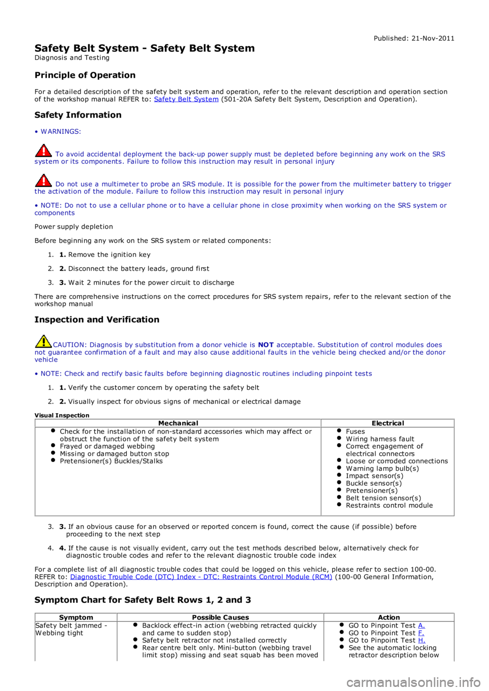
Safety Belt System - Safety Belt System
Diagnosi s and Tes ti ng
Principle of Operation
For a detail ed descripti on of the safet y belt s ys tem and operati on, refer t o t he relevant des cri pti on and operati on s ect ionof the workshop manual REFER to: Safet y Belt Sys tem (501-20A Safety Bel t Sys t em, Des cri pti on and Operati on).
Safety Information
• W ARNINGS:
To avoid accidental depl oyment t he back-up power supply must be depl et ed before begi nning any work on the SRSs ys t em or i ts component s . Fai lure to foll ow t his i nst ruct ion may res ul t in pers onal injury
Do not us e a mult imet er to probe an SRS module. It is pos s ible for the power from the mult imet er bat tery t o triggert he act ivati on of the modul e. Fai lure to foll ow t his i ns t ructi on may resul t in personal injury
• NOTE: Do not t o us e a cell ul ar phone or t o have a cell ul ar phone i n clos e proximity when worki ng on the SRS sys t em orcomponents
Power supply deplet ion
Before begi nni ng any work on the SRS sys tem or rel at ed component s:
1. Remove the i gnit ion key1.
2. Dis connect the bat tery leads , ground fi rs t2.
3. W ait 2 mi nut es for t he power ci rcuit t o dis charge3.
There are comprehens i ve ins truct ions on t he correct procedures for SRS s ys tem repairs , refer t o t he rel evant s ect ion of t heworks hop manual
Inspection and Verification
CAUTION: Di agnos is by s ubs ti tut ion from a donor vehicle is NO T acceptabl e. Subs ti tut ion of cont rol modules doesnot guarant ee confirmat ion of a faul t and may al so caus e addit ional fault s in the vehicle bei ng checked and/or the donorvehi cl e
• NOTE: Check and recti fy bas ic faul ts before beginni ng diagnos t ic rout ines i ncl udi ng pinpoint t es t s
1. Verify t he cus t omer concern by operat ing t he s afet y belt1.
2. Vis ually ins pect for obvious s igns of mechani cal or electrical damage2.
Visual InspectionMechanicalElectrical
Check for t he ins tal lati on of non-s tandard acces s ori es which may affect orobs truct t he functi on of the safet y belt s ys temFrayed or damaged webbi ngMi ss i ng or damaged but ton s t opPret ensi oner(s ) Buckl es/Stal ks
FusesW iri ng harnes s faultCorrect engagement ofelectrical connect orsLoose or corroded connect ionsW arning l amp bulb(s)Impact s ens or(s )Buckl e s ens or(s )Pret ensi oner(s )Belt t ensi on s ens or(s )Res traints cont rol module
3. If an obvious cause for an obs erved or report ed concern is found, correct t he caus e (if pos s ible) beforeproceeding t o t he next s t ep3.
4. If t he caus e is not vis ually evi dent , carry out t he t es t met hods des cri bed bel ow, alternat ively check fordi agnos ti c troubl e codes and refer t o t he rel evant diagnost ic troubl e code index4.
For a compl ete lis t of all di agnos ti c troubl e codes that coul d be l ogged on t his vehicle, pleas e refer to s ect ion 100-00.REFER to: Di agnos ti c Trouble Code (DTC) Index - DTC: Res trai nts Cont rol Module (RCM) (100-00 General Informati on,Des cript ion and Operat ion).
Symptom Chart for Safety Belt Rows 1, 2 and 3
SymptomPossible CausesActionSafet y belt jammed -W ebbing ti ghtBackl ock effect-in act ion (webbing ret ract ed qui ckl yand came t o s udden st op)Safet y belt ret ract or not i ns t alled correctl yRear cent re bel t onl y. Mini-but t on (webbing travell imi t st op) mis s ing and seat s quab has been moved
GO t o Pi npoint Tes t A.GO t o Pi npoint Tes t F.GO t o Pi npoint Tes t H.See the aut omati c lockingret ractor des cript ion below
Page 2725 of 3229

Contents
5
R
ENGINE COOLANT CHECK ............................ 163
BRAKE AND CLUTCH FLUID CHECK ............. 165
POWER STEERING FLUID CHECK ................ 166
WASHER FLUID CHECK ................................ 167
TECHNICAL SPECIFICATIONS ...................... 169
Vehicle battery
BATTERY WARNING SYMBOLS ................... 171
BATTERY CARE ............................................ 171
USING BOOSTER CABLES ............................ 173
CHARGING THE VE HICLE BATTERY ............. 174
CHANGING THE VE HICLE BATTERY ............. 174
Wheels and tyres
GENERAL INFORMATION ............................. 176
TYRE CARE ................................................... 177
USING WINTER TYRES................................. 183
CHANGING A ROAD WHEEL ......................... 183
TYRE REPAIR KIT ......................................... 187
USING SNOW CHAINS.................................. 192
TYRE GLOSSARY.......................................... 193
TECHNICAL SPECIFICATIONS ...................... 194
Fuses
FUSE BOX LOCATIONS ................................. 195
CHANGING A FUSE ....................................... 195
FUSE SPECIFICATION CHART....................... 196
Emergency equipment
HAZARD WARNING FLASHERS .................... 204
WARNING TRIANGLE ................................... 204
Status after a collision
DRIVING AFTER A COLLISION...................... 205
INSPECTING SAFETY SYSTEM COMPONENTS ...
206
Vehicle recovery
TOWING POINTS .......................................... 207
LASHING POINTS ......................................... 208
TRANSPORTING THE VEHICLE..................... 208
TOWING THE VEHICLE ON FOUR WHEELS .. 208
Vehicle identification
VEHICLE IDENTIFICATION PLATE................. 210
VEHICLE IDENTIFI CATION NUMBER (VIN) ... 210
VEHICLE BUILD DATE PLATE ....................... 210
Technical specifications
ENGINE SPECIFICATIONS ............................ 211
WEIGHTS...................................................... 212
DIMENSIONS................................................ 213
Type approval
Declarations of conformity ........................... 215
Audio introduction
RADIO RECEPTION....................................... 218
Audio unit overview
AUDIO UNIT OVERVIEW............................... 219
Audio unit operation
ON OR OFF CONTROL .................................. 223
VOLUME CONTROL ...................................... 223
AUDIO CONTROL ......................................... 223
WAVEBAND BUTTON ................................... 224
AUTOSTORE CONTROL ................................ 225
STATION PRESET BUTTONS ........................ 226
TRAFFIC INFORMATION CONTROL .............. 226
Audio unit menus
RADIO DATA SYSTEM (RDS) ....................... 228
REGIONAL MODE (REG) .............................. 228
ENHANCED OTHER NETWORK (RDS-EON).. 229
ALTERNATIVE FREQUENCIES ...................... 229
NEWS BROADCASTS ................................... 230
PRIORITY PROGRAMME TYPE (PTY) .......... 231
RESETTING THE AUDIO UNIT ...................... 233
Digital audio broadcasting
GENERAL INFORMATION ............................. 234
AUDIO CONTROLS ....................................... 235
DISPLAY OPTIONS ....................................... 236
CHANNEL AUTOMATIC TUNING................... 236
CHANNEL OPTIONS ..................................... 236
PRESET BUTTONS ....................................... 238
SETTINGS..................................................... 240
Compact disc player
LOADING COMPACT DISCS ......................... 245
EJECTING COMPACT DISCS ........................ 246
EJECTING MULTIPLE CO MPACT DISCS....... 246
COMPACT DISC SELECTION ........................ 246
COMPACT DISC PLAYBACK ......................... 246
Page 2915 of 3229
195
Fuses
R
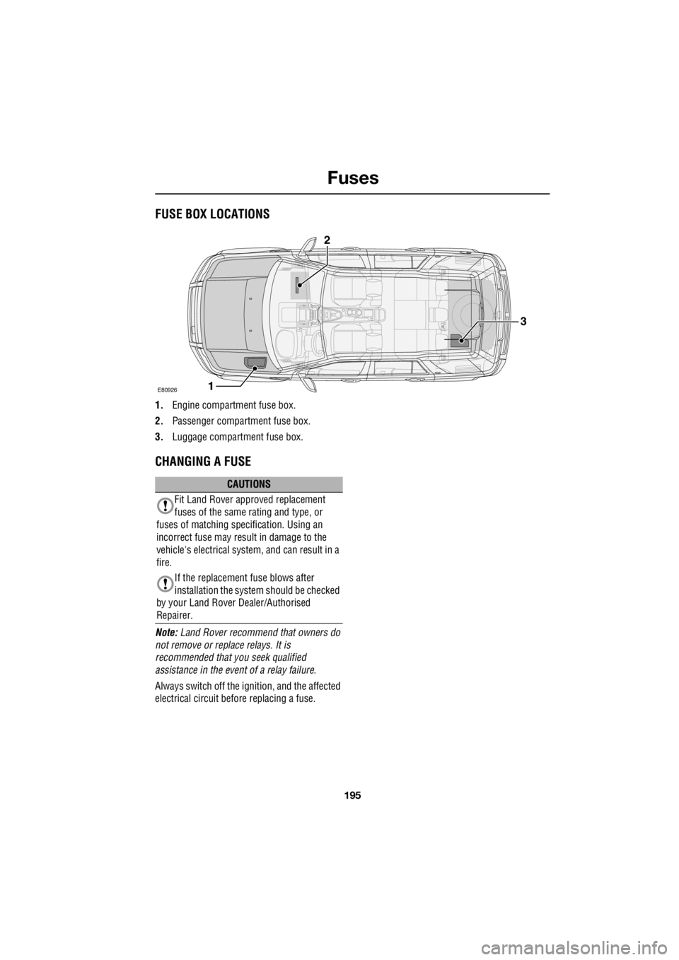
FusesFUSE BOX LOCATIONS
1. Engine compartment fuse box.
2. Passenger compartment fuse box.
3. Luggage compartment fuse box.
CHANGING A FUSE
Note: Land Rover recommend that owners do
not remove or repl ace relays. It is
recommended that you seek qualified
assistance in the event of a relay failure.
Always switch off the i gnition, and the affected
electrical circuit before replacing a fuse.
E80926
3
1
2
CAUTIONS
Fit Land Rover approved replacement
fuses of the same rating and type, or
fuses of matching spec ification. Using an
incorrect fuse may result in damage to the
vehicle's electrical system, and can result in a
fire.
If the replacement fuse blows after
installation the syst em should be checked
by your Land Rover Dealer/Authorised
Repairer.
Page 2916 of 3229
Fuses
196
L
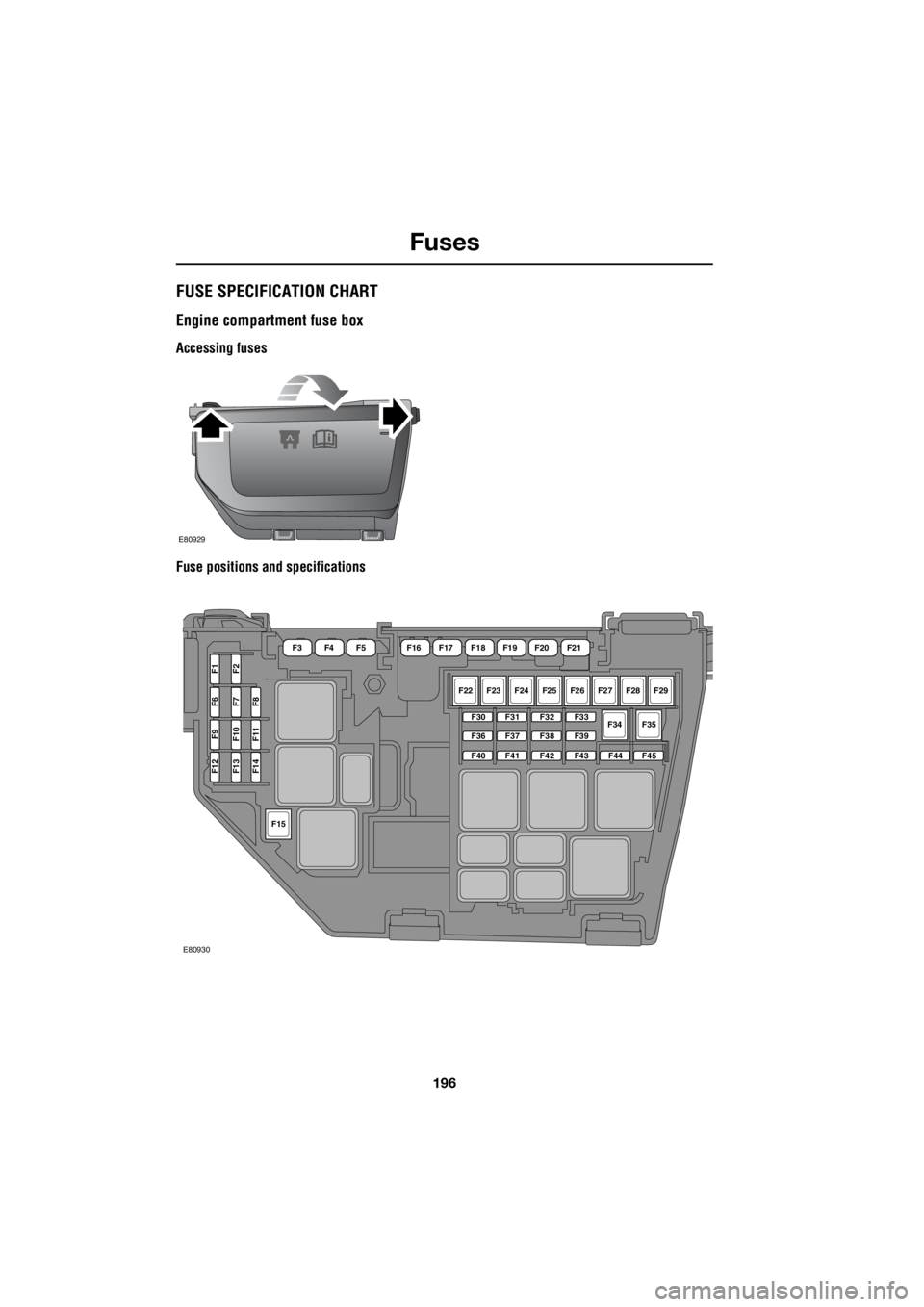
FUSE SPECIFICATION CHART
Engine compartment fuse box
Accessing fuses
Fuse positions and specifications
E80929
F22F23F24F25F26F27F28F29
F34F35F30
F36
F40
F31
F37
F41
F32
F38
F42
F33
F39
F43F44F45
F15
F12F13F14
F9F10F11
F6F7F8
F1F2
F16F17F18F19F20F21F3F4F5
E80930