2006 LAND ROVER FRELANDER 2 height
[x] Cancel search: heightPage 31 of 3229
Invert the compres s or and gravi ty drain the oi l into a calibrated meas uri ng cyl inder. Rotat e t he compres sor clut ch tomake s ure the compres s or is complet el y drai ned.Note the quanti ty of oi l drained (Y cm³).Calculate the quanti ty of oi l to be drained from t he new compres sor us ing t he fol lowi ng formula:X cm³ — (Y cm³ +20 cm³) = Q cm³Remove the drain pl ug from the new compres s or and drain Q cm3 of oi l. ins t al l and tight en t he compres sor drai nplug.
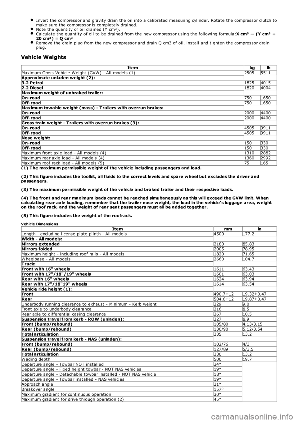
Vehicle Weights
Itemkglb
Maximum Gros s Vehicle W eight (GVW ) - Al l model s (1)25055511Approximate unladen w eight (2):
3.2 Petrol18254015
2.2 Diesel18204004Maximum weight of unbraked trailer:
On-road7501650
Off-road7501650Maximum towable weight (mass) - T railers with overrun brakes:
On-road20004400
Off-road20004400Gross train weight - T railers with overrun brakes (3):
On-road45059911
Off-road45059911Nose w eight:
On-road150330
Off-road150330Maximum front axl e l oad - All models (4)13102882
Maximum rear axle load - All models (4)13602992
Maximum roof rack l oad - All models (5)75165(1) T he maximum permissible weight of the vehicle including passengers and load.
(2) T his figure includes the toolkit, all fluids to the correct levels and spare w heel but excludes the driver andpassengers.
(3) T he maximum permissible weight of the vehicle and braked trailer and their respective loads.
(4) T he front and rear maximum loads cannot be reached simultaneously as this will exceed the GVW limit. Whencalculating rear axle loading, remember that the trailer nose w eight, the load in the vehicle' s luggage area, w eighton the roof rack, and the weight of rear seat passengers must all be added together.
(5) T his figure includes the weight of the roofrack.
Vehicle Dimensions
ItemmminLengt h - excluding l icens e pl ate pl int h - All models4500177.2
Width - All models:
Mirrors extended218085.83Mirrors folded200578.95
Maximum height - including roof rail s - Al l model s182071.65
W heelbas e - Al l model s2660104.7T rack:
Front w ith 16" wheels161163.43
Front w ith 17"/18"/19" wheels160163.03Rear with 16" wheels162463.94
Rear with 17"/18"19" wheels161463.54
Vehicle ride height (1):Front490.7±1219.32±0.47
Rear504.6±1219.87±0.47
Underbody running cl earance t o exhaus t - Mi nimum - Kerb wei ght2299.0Front axle t o underbody clearance2168.5
Rear axl e t o different ial cas i ng cl earance26710.5
Suspension travel from kerb - ROW (unladen):2278.9Front (bump/rebound)105/804.13/3.15
Rear (bump/rebound)130/905.12/3.54
T otal articulation33513.2Suspension travel from kerb - NAS (unladen):
Front (bump/rebound)102/764/3
Rear (bump/rebound)127/895/3.5T otal articulation33013.2
W adi ng dept h50019.7
Depart ure angle - Towbar NOT ins tall ed34°Depart ure angle - Fi xed hei ght towbar - NOT NAS vehicles19°
Depart ure angle - Detachabl e towbar ins t al led - NOT NAS vehicle18°
Depart ure angle - Towbar i ns t alled - NAS vehi cl es19°Approach angl e31°
Breakover angle157°
Maximum gradient for conti nuous operat ion30°Maximum gradient for drive t hrough operat ion (2)45°
Page 32 of 3229
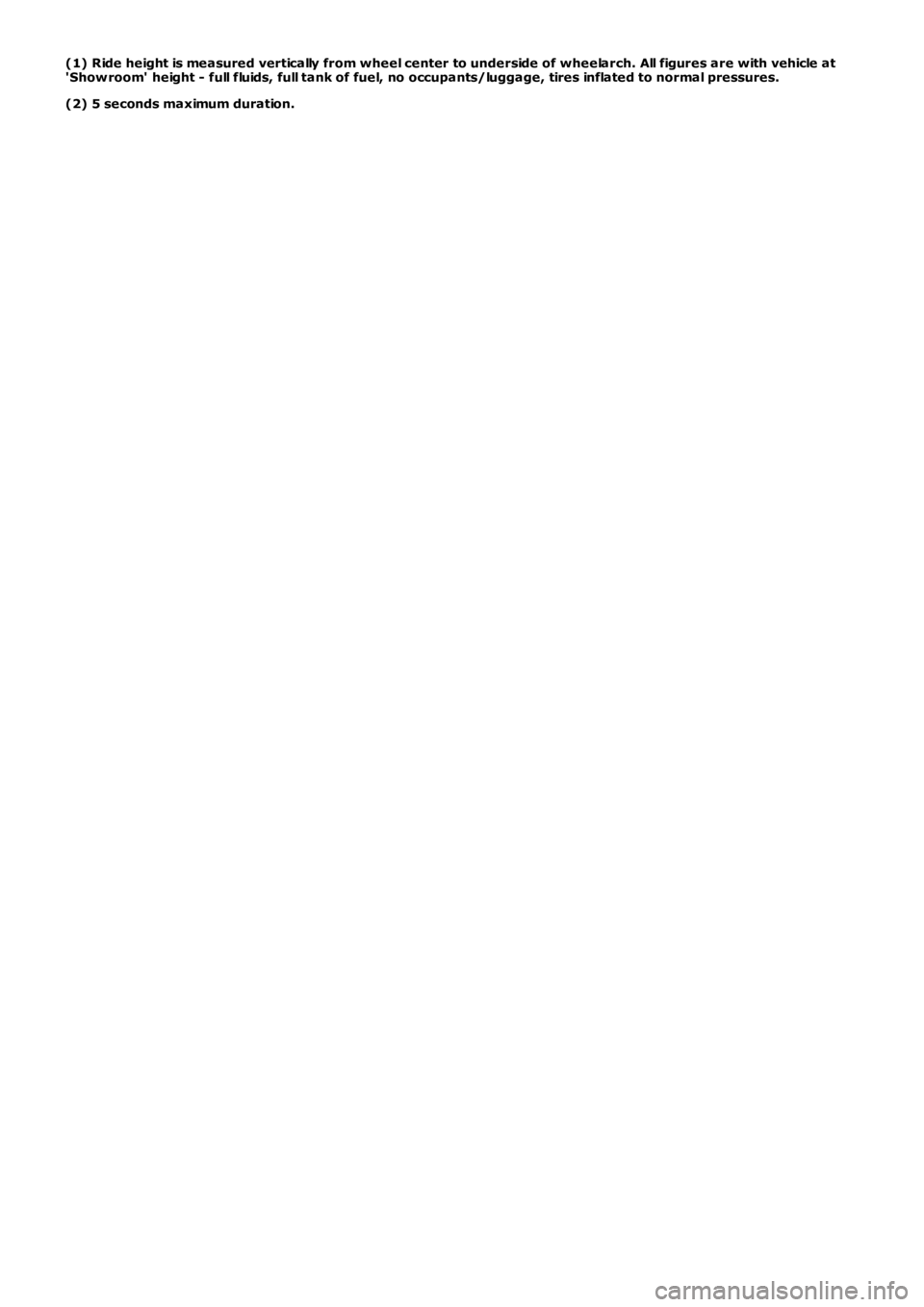
(1) Ride height is measured vertically from wheel center to underside of wheelarch. All figures are with vehicle at'Show room' height - full fluids, full tank of fuel, no occupants/luggage, tires inflated to normal pressures.
(2) 5 seconds maximum duration.
Page 88 of 3229
DT CDescriptionPossible CauseAction
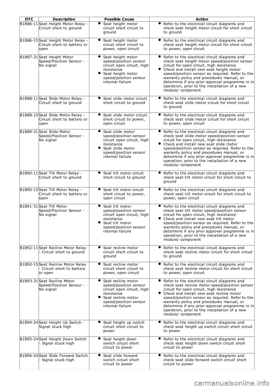
B1B86-11Seat Hei ght Motor Relay -Circui t s hort to groundSeat height motorcircui t s hort circuit t oground
Refer to t he elect rical circuit di agrams andcheck seat height mot or ci rcuit for s hort ci rcuitt o ground
B1B86-15Seat Hei ght Motor Relay -Circui t s hort to bat t ery oropen
Seat height motorcircui t s hort circuit t opower, open circui t
Refer to t he elect rical circuit di agrams andcheck seat height mot or ci rcuit for s hort ci rcuitt o power, open circui t
B1B87-31Seat Hei ght MotorSpeed/Pos i ti on Sens or -No s i gnal
Seat height motors peed/posi ti on s ens orcircui t open ci rcuit , highresi s tanceSeat height motors peed/posi ti on s ens ori nternal fai lure
Refer to t he elect rical circuit di agrams andcheck seat height mot or speed/pos it ion s ensorci rcuit for open circui t, hi gh res is t anceCheck and ins t al l new s eat hei ght mot ors peed/pos it ion s ensor as requi red. Refer to thewarrant y policy and procedures manual, ordet ermi ne if any prior approval programme i s inoperat ion, pri or to t he i ns t allat ion of a newmodul e/ component
B1B88-11Seat Sl ide Mot or Relay -Circui t s hort to groundSeat s lide motor circui ts hort circui t to groundRefer to t he elect rical circuit di agrams andcheck seat s li de mot or ci rcuit for s hort circui tt o ground
B1B88-15Seat Sl ide Mot or Relay -Circui t s hort to bat t ery oropen
Seat s lide motor circui ts hort circui t to power,open circui t
Refer to t he elect rical circuit di agrams andcheck seat s li de mot or ci rcuit for s hort circui tt o power, open circui t
B1B89-31Seat Sl ide Mot orSpeed/Pos i ti on Sens or -No s i gnal
Seat s lide motors peed/posi ti on s ens orcircui t open ci rcuit , highresi s tanceSeat s lide motors peed/posi ti on s ens ori nternal fai lure
Refer to t he elect rical circuit di agrams andcheck seat s li de mot or s peed/pos it ion s ensorci rcuit for open circui t, hi gh res is t anceCheck and ins t al l new s eat s l ide mot ors peed/pos it ion s ensor as requi red. Refer to thewarrant y policy and procedures manual, ordet ermi ne if any prior approval programme i s inoperat ion, pri or to t he i ns t allat ion of a newmodul e/ component
B1B90-11Seat Ti lt Mot or Rel ay -Circui t s hort to groundSeat ti lt mot or circuits hort circui t to groundRefer to t he elect rical circuit di agrams andcheck seat t il t motor circui t for s hort circui t toground
B1B90-15Seat Ti lt Mot or Rel ay -Circui t s hort to bat t ery oropen
Seat ti lt mot or circuits hort circui t to power,open circui t
Refer to t he elect rical circuit di agrams andcheck seat t il t motor circui t for s hort circui t topower, open circui t
B1B91-31Seat Ti lt Mot orSpeed/Pos i ti on Sens or -No s i gnal
Seat ti lt mot ors peed/posi ti on s ens orcircui t open ci rcuit , highresi s tanceSeat ti lt mot ors peed/posi ti on s ens ori nternal fai lure
Refer to t he elect rical circuit di agrams andcheck seat t il t motor s peed/posi ti on s ens orci rcuit for open circui t, hi gh res is t anceCheck and ins t al l new s eat t il t mot ors peed/pos it ion s ensor as requi red. Refer to thewarrant y policy and procedures manual, ordet ermi ne if any prior approval programme i s inoperat ion, pri or to t he i ns t allat ion of a newmodul e/ component
B1B92-11Seat Recli ne Mot or Rel ay- Circui t s hort t o groundSeat recli ne mot orcircui t s hort circuit t oground
Refer to t he elect rical circuit di agrams andcheck seat recl ine mot or ci rcuit for short ci rcuitt o ground
B1B92-15Seat Recli ne Mot or Rel ay- Circui t s hort t o batt eryor open
Seat recli ne mot orcircui t s hort circuit t opower, open circui t
Refer to t he elect rical circuit di agrams andcheck seat recl ine mot or ci rcuit for short ci rcuitt o power, open circui t
B1B93-31Seat Recli ne Mot orSpeed/Pos i ti on Sens or -No s i gnal
Seat recli ne mot ors peed/posi ti on s ens orcircui t open ci rcuit , highresi s tanceSeat recli ne mot ors peed/posi ti on s ens ori nternal fai lure
Refer to t he elect rical circuit di agrams andcheck seat recl ine mot or speed/pos it ion s ens orci rcuit for open circui t, hi gh res is t anceCheck and ins t al l new s eat recl ine motors peed/pos it ion s ensor as requi red. Refer to thewarrant y policy and procedures manual, ordet ermi ne if any prior approval programme i s inoperat ion, pri or to t he i ns t allat ion of a newmodul e/ component
B1B94-24Seat Hei ght Up Swit ch -Signal st uck highSeat height up s wit chcircui t s hort circuit t opower
Refer to t he elect rical circuit di agrams andcheck seat height up s wit ch circui t short ci rcuitt o power
B1B95-24Seat Hei ght Down Swit ch- Signal s tuck highSeat height downs wi tch circui t shortcircui t to power
Refer to t he elect rical circuit di agrams andcheck seat height down s wit ch circuit shortci rcuit t o power
B1B96-24Seat Sl ide Forward Swi tch- Signal s tuck highSeat s lide forwards wi tch circui t shortcircui t to power
Refer to t he elect rical circuit di agrams andcheck seat s li de forward swi tch circui t s hortci rcuit t o power
Page 101 of 3229
DT CDescriptionPossible CauseAction
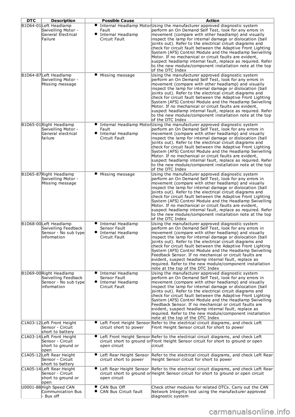
B1D64-01Left HeadlampSwivell ing Mot or -General Elect ricalFailure
Internal Headlamp Mot orFaultInternal HeadlampCi rcuit Faul t
Us ing t he manufacturer approved diagnost ic sys temperform an On Demand Self Tes t, l ook for any errors i nmovement (compare wi th other headl amp) and vi sual lyins pect t he lamp for i nt ernal damage or di s locat ion (balljoi nt s out). Refer t o t he electrical ci rcuit diagrams andcheck for circui t faul t bet ween t he Adapt ive Front Light ingSys t em (AFS) Cont rol Modul e and t he Headl amp Swi vel lingMotor. If no mechanical or circui t fault s are evident ,s us pect headlamp int ernal fault , replace as requi red. Referto the new modul e/component i nst all at ion not e at t he topof the DTC Index
B1D64-87Left HeadlampSwivell ing Mot or -Mis s ing mess age
Mi ss i ng mes sageUs ing t he manufacturer approved diagnost ic sys temperform an On Demand Self Tes t, l ook for any errors i nmovement (compare wi th other headl amp) and vi sual lyins pect t he lamp for i nt ernal damage or di s locat ion (balljoi nt s out). Refer t o t he electrical ci rcuit diagrams andcheck for circui t faul t bet ween t he Adapt ive Front Light ingSys t em (AFS) Cont rol Modul e and t he Headl amp Swi vel lingMotor. If no mechanical or circui t fault s are evident ,s us pect headlamp int ernal fault , replace as requi red. Referto the new modul e/component i nst all at ion not e at t he topof the DTC IndexB1D65-01Right HeadlampSwivell ing Mot or -General elect ricalfai lure
Internal Headlamp Mot orFaultInternal HeadlampCi rcuit Faul t
Us ing t he manufacturer approved diagnost ic sys temperform an On Demand Self Tes t, l ook for any errors i nmovement (compare wi th other headl amp) and vi sual lyins pect t he lamp for i nt ernal damage or di s locat ion (balljoi nt s out). Refer t o t he electrical ci rcuit diagrams andcheck for circui t faul t bet ween t he Adapt ive Front Light ingSys t em (AFS) Cont rol Modul e and t he Headl amp Swi vel lingMotor. If no mechanical or circui t fault s are evident ,s us pect headlamp int ernal fault , replace as requi red. Referto the new modul e/component i nst all at ion not e at t he topof the DTC Index
B1D65-87Right HeadlampSwivell ing Mot or -Mis s ing mess age
Mi ss i ng mes sageUs ing t he manufacturer approved diagnost ic sys temperform an On Demand Self Tes t, l ook for any errors i nmovement (compare wi th other headl amp) and vi sual lyins pect t he lamp for i nt ernal damage or di s locat ion (balljoi nt s out). Refer t o t he electrical ci rcuit diagrams andcheck for circui t faul t bet ween t he Adapt ive Front Light ingSys t em (AFS) Cont rol Modul e and t he Headl amp Swi vel lingMotor. If no mechanical or circui t fault s are evident ,s us pect headlamp int ernal fault , replace as requi red. Referto the new modul e/component i nst all at ion not e at t he topof the DTC Index
B1D68-00Left HeadlampSwivell ing FeedbackSens or - No s ub t ypeinformat ion
Internal HeadlampSensor FaultInternal HeadlampCi rcuit Faul t
Us ing t he manufacturer approved diagnost ic sys temperform an On Demand Self Tes t, l ook for any errors i nmovement (compare wi th other headl amp) and vi sual lyins pect t he lamp for i nt ernal damage or di s locat ion (balljoi nt s out). Refer t o t he electrical ci rcuit diagrams andcheck for circui t faul t bet ween t he Adapt ive Front Light ingSys t em (AFS) Cont rol Modul e and t he Headl amp Swi vel lingFeedback Sens or. If no mechani cal or circuit fault s areevi dent , s us pect headlamp int ernal fault , replace asrequired. Refer t o t he new modul e/component ins t al lat ionnot e at t he t op of the DTC IndexB1D69-00Right HeadlampSwivell ing FeedbackSens or - No s ub t ypeinformat ion
Internal HeadlampSensor FaultInternal HeadlampCi rcuit Faul t
Us ing t he manufacturer approved diagnost ic sys temperform an On Demand Self Tes t, l ook for any errors i nmovement (compare wi th other headl amp) and vi sual lyins pect t he lamp for i nt ernal damage or di s locat ion (balljoi nt s out). Refer t o t he electrical ci rcuit diagrams andcheck for circui t faul t bet ween t he Adapt ive Front Light ingSys t em (AFS) Cont rol Modul e and t he Headl amp Swi vel lingFeedback Sens or. If no mechani cal or circuit fault s areevi dent , s us pect headlamp int ernal fault , replace asrequired. Refer t o t he new modul e/component ins t al lat ionnot e at t he t op of the DTC Index
C1A03-12Left Front HeightSens or - Circui ts hort t o batt ery
Left Front Hei ght Sens orcircui t s hort to powerRefer to the el ect ri cal circui t diagrams , and check LeftFront Height Sens or circuit for s hort to power
C1A03-14Left Front HeightSens or - Circui ts hort t o ground oropen
Left Front Hei ght Sens orcircui t s hort to ground oropen circui t
Refer to the el ect ri cal circui t diagrams , and check LeftFront Height Sens or circuit for s hort to ground or openci rcuit
C1A05-12Left Rear HeightSens or - Circui ts hort t o batt ery
Left Rear Height Sens orcircui t s hort to powerRefer to the el ect ri cal circui t diagrams , and check Left RearHeight Sens or circuit for s hort to power
C1A05-14Left Rear HeightSens or - Circui ts hort t o ground oropen
Left Rear Height Sens orcircui t s hort to ground oropen circui t
Refer to the el ect ri cal circui t diagrams , and check Left RearHeight Sens or circuit for s hort to ground or open ci rcuit
U0001-88High Speed CANCommunicati on Bus- Bus off
CAN Bus OffCAN Bus Ci rcuit faultCheck ot her modul es for rel ated DTCs . Carry out the CANNetwork Int egrit y t est us i ng the manufact urer approveddiagnos t ic s ys tem
Page 164 of 3229
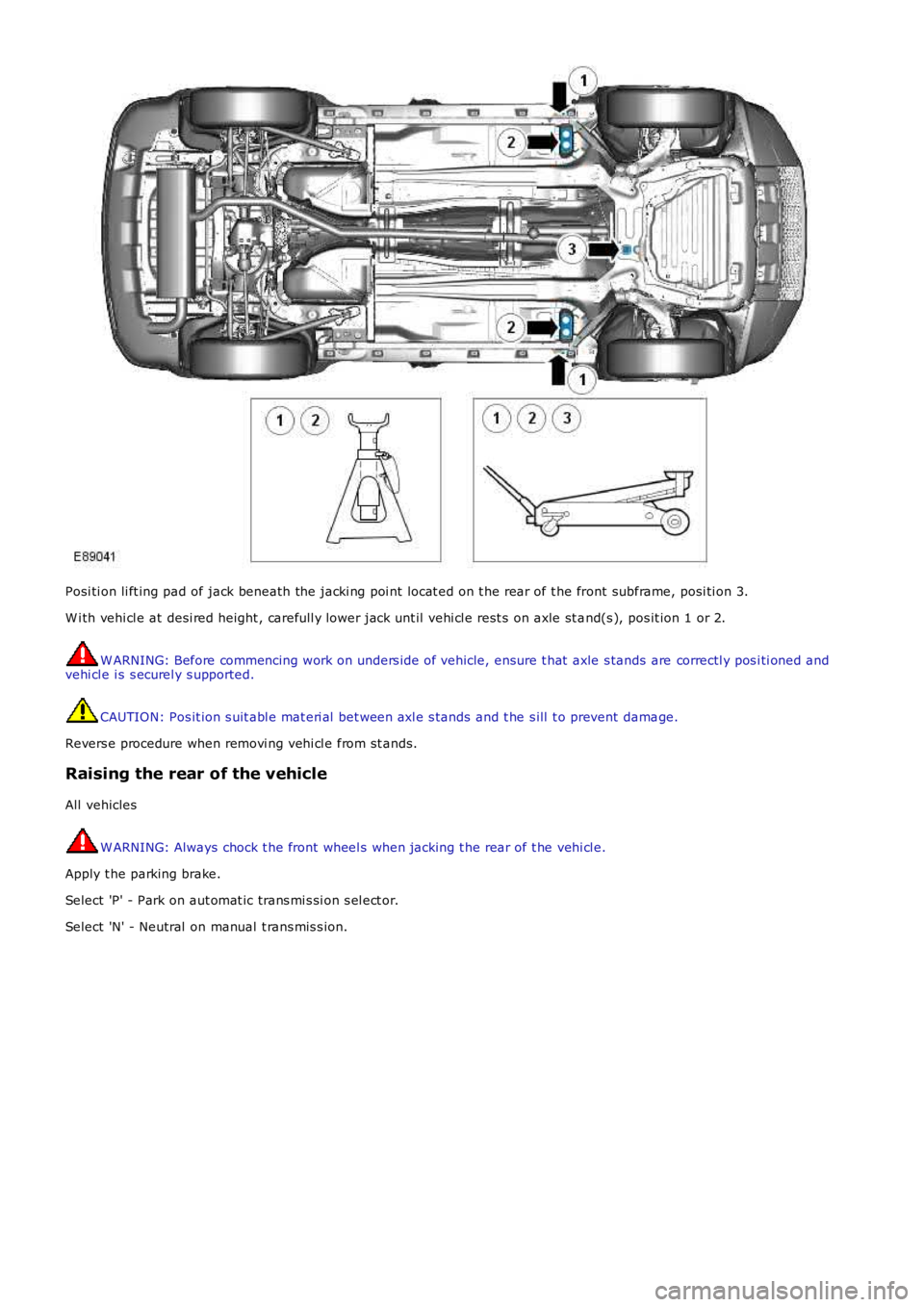
Posi ti on li ft ing pad of jack beneath the jacki ng poi nt locat ed on t he rear of t he front subframe, posi ti on 3.
W i th vehi cl e at desi red height , carefull y lower jack unt il vehi cl e rest s on axle st and(s ), pos it ion 1 or 2.
W ARNING: Before commencing work on unders ide of vehicle, ensure t hat axle s tands are correctl y pos i ti oned andvehi cl e i s s ecurel y s upported.
CAUTION: Pos it ion s uit abl e mat eri al bet ween axl e s tands and t he s ill t o prevent damage.
Revers e procedure when removi ng vehi cl e from st ands.
Raising the rear of the vehicle
All vehicles
W ARNING: Always chock t he front wheel s when jacking t he rear of t he vehi cl e.
Apply t he parking brake.
Select 'P' - Park on aut omat ic trans mi s si on s el ect or.
Select 'N' - Neutral on manual t rans mis s ion.
Page 165 of 3229
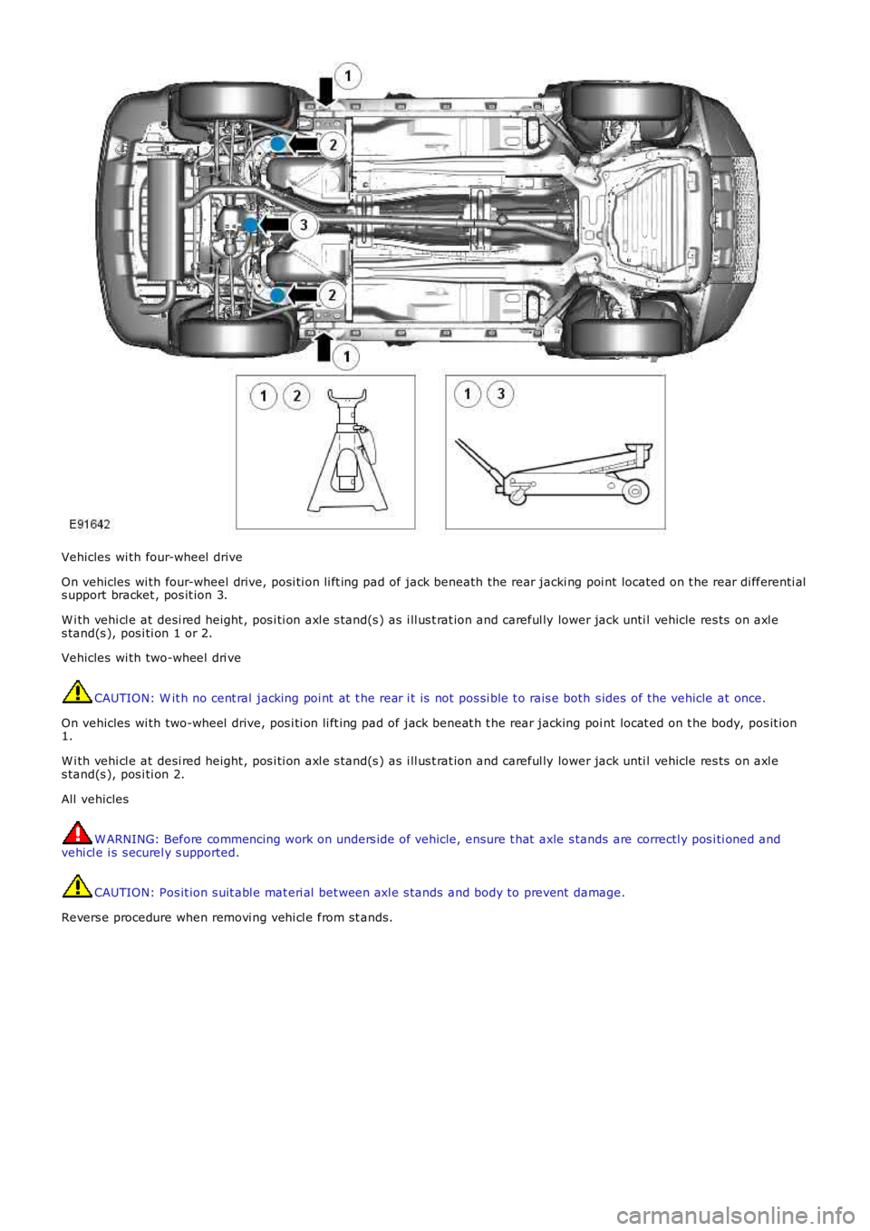
Vehicles wi th four-wheel drive
On vehicles wi th four-wheel drive, posi ti on li ft ing pad of jack beneath the rear jacki ng poi nt located on t he rear di fferenti als upport bracket , pos it ion 3.
W i th vehi cl e at desi red height , pos i ti on axl e s tand(s ) as i ll us t rat ion and careful ly lower jack unti l vehicle res ts on axl es tand(s ), pos i ti on 1 or 2.
Vehicles wi th two-wheel dri ve
CAUTION: W it h no cent ral jacking poi nt at t he rear i t is not pos si ble t o rais e both s ides of the vehicle at once.
On vehicles wi th two-wheel drive, pos i ti on li ft ing pad of jack beneat h t he rear jacking poi nt locat ed on t he body, pos it ion1.
W i th vehi cl e at desi red height , pos i ti on axl e s tand(s ) as i ll us t rat ion and careful ly lower jack unti l vehicle res ts on axl es tand(s ), pos i ti on 2.
All vehicles
W ARNING: Before commencing work on unders ide of vehicle, ensure t hat axle s tands are correctl y pos i ti oned andvehi cl e i s s ecurel y s upported.
CAUTION: Pos it ion s uit abl e mat eri al bet ween axl e s tands and body to prevent damage.
Revers e procedure when removi ng vehi cl e from st ands.
Page 166 of 3229

Publi s hed: 11-May-2011
Jacking and Lifting - Lifting
Des cript ion and Operat ion
Two-Post Lift
W ARNING: Make sure t hat t he vehicle i s s table before commencing work.
CAUTION: If the drive s haft (s ) are to be removed, rel eas e t he parking brake and s el ect NEUTRAL 'N' i n t het ransmis s ion i n order t hat t he s haft (s ) can be rot ated when the vehicle is rais ed to the des ired height.
1. Pos i ti on the vehicle wit h t he cent re of the l ift pill ars al igned approxi mat el y wi th t he front of the driver/pass enger s eatcus hions .
ItemPart NumberDescription
1-Two post l ift locati ons - Cus t omer jacki ng points2-Opti onal, Two-pos t front li ft l ocat ions - Body mounti ng us ed in vehicle product ion
2. Ext end t he li ft ing arms and pos it ion t he pad of each l ifti ng arm beneat h t he approved poi nt s .
3. Rais e t he vehi cl e unti l the wheels are just cl ear of t he ground and check t hat the pads of each lift ing arm are s ti llcorrect ly pos it ioned.
4. Rais e t he vehi cl e t o t he des i red height .
5. Ensure t he vehi cl e is correctl y s upport ed wi th the l ifti ng pads in full cont act with t he approved poi nt s .
Vehicle on wheels - Four-Post Ramp
• W ARNINGS:
If the drive s haft (s ) are t o be dis connected, it will be necess ary to rais e al l four wheel s off t he ramp in order thatt he shaft(s ) can be rot at ed. Refer to the 'W heel Free Lift - Four-Pos t Ramp' s ecti on below for li ft ing i ns t ructi ons thenrel eas e t he parki ng brake and s elect NEUTRAL i n t he transmis si on.
Do not pus h t he vehi cl e backwards and forwards along t he ramp in order to gai n acces s t o the drive s haft fixi ngs .
Posi ti on t he vehi cl e on t he ramp wit h t he front and rear wheel s equidis t ant from t he ends of t he ramp. Chock t he wheel s,s elect NEUTRAL i n t he transmis si on and where pract ical, apply the parki ng brake.
Wheel-Free Lift - Four-Post Ramp
Page 167 of 3229
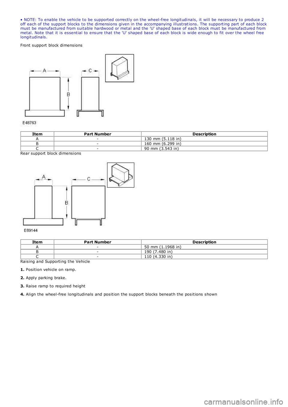
• NOTE: To enable t he vehi cle t o be s upport ed correctl y on t he wheel -free longit udi nal s, i t wil l be neces s ary t o produce 2off each of the support blocks t o the di mens ions given in the accompanying ill ust rations . The s upport ing part of each bl ockmus t be manufactured from s uit able hardwood or met al and the 'U' shaped bas e of each bl ock mus t be manufact ured frommet al . Note that it i s es sent ial to ens ure that t he 'U' s haped bas e of each block is wide enough to fit over t he wheel freelongit udinals .
Front s upport bl ock di mens ions
ItemPart NumberDescriptionA-130 mm (5.118 in)
B-160 mm (6.299 in)
C-90 mm (3.543 in)Rear support block dimens i ons
ItemPart NumberDescription
A-50 mm (1.1968 in)B-190 (7.480 in)
C-110 (4.330 in)
Rais ing and Support ing t he Vehicle
1. Posi ti on vehi cl e on ramp.
2. Appl y parking brake.
3. Rais e ramp t o required height
4. Ali gn the wheel -free l ongi tudinals and pos it ion the s upport blocks beneat h the pos it ions s hown