2006 LAND ROVER FRELANDER 2 height
[x] Cancel search: heightPage 645 of 3229
Cylinder Head Oil Supply
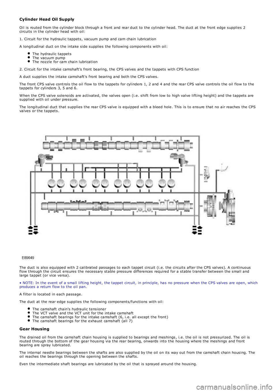
Oil is routed from the cylinder block t hrough a front and rear duct to the cylinder head. The duct at t he front edge s upplies 2circuit s in t he cylinder head wit h oil:
1. Circuit for t he hydraulic t appet s , vacuum pump and cam chain lubricat ion
A longit udinal duct on t he intake s ide s upplies the following component s wit h oil:
The hydraulic t appet sThe vacuum pumpThe noz zle for cam chain lubricat ion
2. Circuit for t he intake camshaft 's front bearing, t he CPS valves and t he t appet s wit h CPS funct ion
A duct s upplies t he intake camshaft 's front bearing and bot h t he CPS valves.
The front CPS valve cont rols t he oil flow to the t appets for cylinders 1, 2 and 4 and t he rear CPS valve controls t he oil flow t o t hetappets for cylinders 3, 5 and 6.
W hen the CPS valve s olenoids are act ivated, t he valves open (i.e. s hift from low to high valve lifting height) and t he t appet s aresupplied wit h oil under pres sure.
The longitudinal duct that s upplies t he rear CPS valve is equipped with a bleed hole. This is t o ens ure t hat no air reaches the CPSvalves or t he t appet s .
The duct is als o equipped wit h 2 calibrat ed pas sages t o each t appet circuit (i.e. t he circuit s after t he CPS valves ). A cont inuousflow t hrough t he circuit ens ures t he necess ary st able pres s ure differences required for a s t able t rans fer between the s mall andlarge tappet (or vice vers a).
• NOTE: In t he event of a s mall lifting height , the t appet circuit , in principle, has no pres s ure when the CPS valves are open, whichproduces a ret urn flow t o t he oil pan.
A filt er is locat ed in each pass age.
The duct at the rear edge s upplies t he following component s/functions wit h oil:
The camshaft chain's hydraulic t ens ionerThe VCT valve and t he VCT unit for t he int ake cams haftThe camshaft bearings for the int ake cams haft (6, i.e. all except t he front )The camshaft bearings for the exhaust cams haft (all 7)
Gear Housing
The drained oil from t he cams haft chain housing is s upplied t o bearings and mes hings, i.e. t he oil is not pres surized. The oil isrouted t hrough the bott om of t he gear hous ing via t he rear bearing, onwards int o t he hous ing where t he mes hings and frontbearing are spray lubricated.
The internal needle bearings bet ween t he s hafts are als o s upplied by t he oil on it s way out from the cams haft chain hous ing. Theoil reaches t he bearings through t he opening bet ween t he s hafts .
Even t he int ermediat e s haft bearings are lubricat ed by t he oil that is s prayed around t he hous ing.
Page 1218 of 3229
The posi ti on of the inlet cams haft is det ermi ned by the ECM us ing s ignals from t he CKP s ens or and t he CMP s ens ors. TheECM can t hen use the VCT sol enoid val ve to cont rol t he angl e of the cams haft by controlli ng t he fl ow of oil t o t he VCT unit .
The camshaft is s ecured t o t he rot or in t he VCT unit . Oil pres s ure suppli ed to eit her s ide of t he VCT unit from t he VCTs olenoi d valve can rot ate the rotor and hence the cams haft i n eit her di recti on. The VCT sol enoi d is operat ed by t he ECMus ing PW M, hi gh frequency s wit chi ng which provi des rapid and preci se cont rol of the i nlet cams haft pos i ti on. The i nletcamshaft pos i ti on can be adjust ed wi thi n 40 degrees of cranks haft rotat ion.
Camshaft Profile Switching (CPS) Control
The inl et cams haft has , in addit ion to t he VCT control, a CPS funct ion whi ch is al so cont roll ed by t he ECM. The CPS cont rolcan vary t he val ve li ft height and durat ion of t he camshaft lobes by adjus ti ng the area of t he hydraul ic t appet whi ch act son one of t wo cam l obe profi les . The CPS cont rol is vi a t wo CPS s olenoid valves , located at each end of the i nlet cams haft.The CPS s olenoid valves cont rol t he posi ti on of hydraul ic t appet as s embli es which can be s et in one of t wo pos it ions; lowand high.
Two CPS s olenoids are us ed so that t he hydraul ic t appet s can be adjus t ed when no load i s applied, for example the camlobes are off t he hydraul ic t appet s and t he cam bas e circl e is act ing on t he t appet , thi s keeps t he s tress on components toa minimum. One CPS s ol enoi d s uppl ies oi l press ure to the hydrauli c t appet s of cyli nders 1, 2 and 4 and the s econd CPSs olenoi d s uppl ies oi l press ure to the tappet s of cylinders 3, 5 and 6.
At engi ne s tart and at low engine oi l temperat ures (below 40°C (104°F)) the ECM does not direct engine oi l pres sure t ot he hydraul ic t appet s and t herefore the hydraul ic t appet s are in t heir s pring loaded, l ow posi ti on.For addit ional informat ion, refer t o: Engi ne - 3.2L (303-01, Descripti on and Operat ion).
Ignition Control
The ECM calculat es the opt imum ignit ion ti ming bas ed on pre-programmed maps and informat ion from t he foll owings ens ors :
CKP s ensorCMP s ensorsMAF s ensorECT s ens orElectric t hrot tl e TP s ensorKnock s ens orsTCMIgni ti on coi ls .
Duri ng engi ne s tarti ng the ECM uses a fi xed ignit ion s et ti ng. W hen the engine has s tart ed and the vehicle is bei ng driven,t he ECM adjus ts the i gni ti on t imi ng accordi ngl y us ing ot her paramet ers s uch as engine s peed, l oad and temperat ure.
Once the engi ne has reached i ts normal operati ng temperature, t he ECM moni tors the si gnal s from the knock sens ors . Ifany of the cyli nders produce knocking, the i gnit ion t imi ng for t hat cyli nder wi ll be retarded unt il t he knocking has s t opped.The ignit ion is t hen gradually advanced back t o t he normal t imi ng or unt il t he knocking re-occurs .
The ECM us es informat ion from the TCM t o provide t orque l imi tat ion during t rans mis s ion s hifts . The i gni ti on ti mi ng isadjus ted t o moment ari ly reduce t he engine t orque output t o give a smoot h t rans mis s ion shi ft and reduce l oad on thet ransmis s ion.
Air Conditioning (A/C) Compressor Control
The ECM controls t he operati on of the A/C compres s or and reacts t o reques ts from t he ATC module vi a t he high s peed CANbus. The compres s or is a variable di s pl acement unit and t he ECM controls , via a sol enoi d, t he dis placement of thecompres sor t o adjus t load during cert ain driving condit ions.
Duri ng engi ne s tart-up, movi ng from a s tandst il l and under hard accelerat ion, the ECM s et s t he mi nimum dis placement oft he compress or t o reduce the effect on t he engi ne t orque output. The ECM uses i nformati on from t he ATC module, t he A/Cpres s ure s ensor, the el ect ri c t hrott le TP s ens or and the ECT sens or to det ermi ne compres sor control . The ATC modulet ransmit s climate control and driver reques ts t o t he ECM and t he ECM det ermi nes the priori ty of thes e request s overengi ne performance.
Page 1800 of 3229
5-Integrat ed Cont rol Module (ICM)
6-Power amplifier
7-Rear parking aid s ens or (4 off)
OVERVIEW
Two l evels of parki ng aid sys tem can be fit ted; a rear only sys t em or a front and rear s yst em.
The parking ai d s yst em provi des an audi ble warning t o t he dri ver when any obs tacles are in the pat h of the vehicle duringforward (i f front s ensors are fi tt ed) or revers e parking manoeuvres . The sys tem consi st s of four ult ras onic s ensors in eachbumper, a parki ng aid modul e and a parki ng aid s wi tch.
At low s peeds , the parki ng aid modul e us es the ul trasonic sens ors t o moni tor t he area around t he front and rear bumpers .If an object i s detected wit hin a monit ored area, t he module t hen outputs a warni ng usi ng t he audi o s ys t em s peakers. Thes ens ors can det ect s oli d objects such as pos ts , wall s and other vehicles and can also det ect l es s s oli d objects such as awire mes h fence. Object s very clos e t o t he ground may not be det ect ed, but becaus e of t hei r low hei ght may not causedamage to the vehicle.
The parking ai d s yst em compris es the foll owing component s:
Parking ai d moduleParking ai d s wit chEight parking ai d s ens ors.
The parking ai d module communi cat es via t he medium s peed Cont roll er Area Net work (CAN) bus wit h t he audi o s yst em vi at he Int egrated Cont rol Modul e (ICM). The audi o s yst em then output s t he appl icabl e warni ng t ones from the front or rears peakers when an object is detect ed. The medi um s peed CAN bus is al s o us ed to col lect vehicle dat a from other vehi cles ys t ems .
Parking Aid Module
The parking ai d module is l ocat ed on the Left Hand (LH) s ide of t he l uggage compart ment , behind t he 'C' pil lar trim panel .
The parking ai d module has t hree connect ors whi ch provide for power, ground and CAN bus connecti ons , front parking ai ds ens ors and rear parking ai d s ens ors .
The medium s peed CAN bus connect ions provi de for t he receipt of the foll owing i nformat ion from ot her s ys tems :
Anti -l ock Brake Sys t em (ABS) modul e - Road s peed si gnalTrans mis s ion Cont rol Modul e (TCM) - Reverse gear engaged si gnalTrai ler module - Trailer at tached to vehicl eIns t rument clus ter - Ambi ent t emperat ure s ignal.
The module al so out puts mess ages on t he medium speed CAN bus whi ch are recei ved by the Int egrated Control Modul e(ICM). The ICM proces s es t hes e mes s ages and convert s t hem int o Media Ori ent ated Sys tem Trans port (MOST) s i gnal swhich are pass ed t o t he audi o s yst em power ampl ifi er. These s ignal s are then us ed by t he power ampl ifier t o emit theappl icable warning t ones from t he front or rear audi o s peakers when an object i s detected by the front or rear parki ng aids ens ors . A warning t one can als o be emi tt ed t o alert the driver to a faul t in the parki ng aid s ys tem.
The parking ai d module performs s elf check rout ines and when t he s yst em is acti ve checks the sens or wiring for short oropen ci rcuit s . If a fault i s detected a code i s s tored in a memory in the modul e and if neces s ary ei ther t he front and/or rears ens ors can be dis abl ed. The driver is made aware of any faul t condit ion by the parki ng aid s wi tch Light Emi tt ing Di ode(LED) flas hing and a conti nuous warning t one bei ng emi tt ed for 3 seconds , in place of the normal short tones when t hes ys t em i s functi oning normal ly. Faul t codes can be read usi ng t he Int egrated Di agnost ic Syst em (IDS) vi a t he diagnost ics ocket.
Parking Aid Sensors
Four ul trasonic sens ors are located i n t he front and rear bumpers . Each s ens or compri s es a s ens or and a bumper ins ert .The ins ert ens ures t hat each s ensor i s correctl y ori entat ed in relat ion t o i ts l ocation i n t he bumper.
Each sens or has a three pin connect or which mat es wit h a bumper harnes s, whi ch in t urn is connect ed to the main bodyharnes s. Three pi ns provide for power s upply, ground and s ignal lines t o and from the parki ng aid modul e.
Each sens or compris es a pl as t ic hous ing which contai ns a piezo elect ric di s c. The disc res onat es at a frequency of 34.8kHz,produci ng t he ult ras oni c output. The di sc al s o receives t he reflected echo s ignal from any objects wit hi n range.
The parking ai d module controls t he operat ion of each sens or usi ng a digi tal output on t he s ignal line. The module controlst he sens or in one of t wo modes ; combi ned transmit ter and receiver mode or receiver mode only.
Parking Aid Switch
Page 1918 of 3229
5-Side turn s ignal l amp
6-Headlamp level ing modul e or Adapt ive Front l ighti ng Sys t em (AFS) control modul e
7-Bat tery Juncti on Box (BJB)8-Column s talk mult ifunct ion s wit ch
9-Revers e l amp s wit ch (Manual trans mi s si on only)
10-Light s wit ch module11-St op lamp swi tch
12-Front height s ens or (Xenon headlamps only)
13-Refl ect or14-Rear lamp as s embly
15-License plate lamps
16-Hi gh mounted s t op lamp17-Central Juncti on Box (CJB)
18-Front fog lamp
19-Headlamp as s embly
OVERVIEW
Three l evel s of ext eri or l ighti ng are avai lable dependi ng on vehicle s peci fi cat ion:
Halogen headl ampsBi-xenon Hi gh Int ensi ty Dis charge (HID) headl ampsBi-xenon HID Adapt ive Front li ghti ng Sys t em (AFS) headlamps .
A l ight s wit ch module i s located i n t he ins t rument panel and all ows t he driver t o s elect the appropri ate operat ion of t heexteri or li ght ing s ys tems .
The rear l amp as sembl ies cont ain si de lamps , s top lamps , revers e l amps , t urn s i gnal indi cat ors and rear fog lamps . OnNort h American Speci ficat ion (NAS) vehicles the rear l amp as s embly als o incl udes a side marker l amp. The rear lampas sembl ies requi re removal for bul b repl acement. Two reflect ors are mount ed in the rear bumper.
All vers ions of t he headl amps have impact res is t ant polycarbonat e l ens '. Removable covers at t he rear of t he headl ampsall ow for bulb replacement. The headlamps requi re removal for bul b repl acement.
The halogen headl amps have large complex surface reflectors to opt imis e t he beam patt erns i n l ow beam only. A hi ghbeam only refl ect or is l ocat ed on t he inboard s i de of the headlamp. Headl amp l evel ing on t he halogen headl amps ismanually adjust ed us ing a rot ary t humbwheel located i n t he li ght swi tch modul e which operat es leveling motors located i nt he headlamp.
The bi-functi on HID headl amps and the AFS headlamps us e a projector unit wit h a D1S xenon bulb whi ch operates i n bothlow and high beam. An addit ional hal ogen hi gh beam only refl ect or is l ocat ed on t he inboard s ide of t he headlamp.Headl amp l evel ing i s aut omat ic on t he HID headl amps . Front and rear hei ght sens ors are located on the Left Hand (LH)s ide of t he front and rear axl es. Thes e meas ure t he vehi cle at ti tude and a headlamp leveling modul e, which is locat ed ont he bul khead 'A' pi ll ar behind t he glovebox, aut omat icall y cont rol s t he headlamp vert ical al ignment.
Headl amp powerwas h i s a s t andard fi tment on HID headlamps .
Turn s i gnal indi cat ors and high and low beam functi ons are cont rol led from t he LH s teeri ng column mul ti functi on s wit ch.The t urn s ignal indicators have a lane change feat ure. A s ingle pres s and rel eas e of t he mult ifunct ion s wi tch i n eit herdirect ion wi ll operat e t he sel ect ed t urn s ignal indicators for 3 cycles .
The exteri or li ght ing i s cont rol led by t he CJB. The CJB i s t he main cont roll ing modul e for vehicle body s yst ems and i slocated behind the gl ovebox in the i nst rument panel.
The CJB provides circui t protect ion for al l ext eri or l ighti ng circui ts .
Exterior Bulb Typ e/Rating
The fol lowing table shows t he bulbs us ed for t he exterior li ght ing sys tem and t hei r type and s peci fi cat ion.
BulbT ypeRating
Halogen Headlamps - Low beam - Rest O f W orl d (ROW )Halogen H755W
Halogen Headlamps - Low beam - Nort h American Specificati on (NAS)Halogen H1155WXenon headl amps - Low/Hi gh BeamXenon D1S35W
Headlamps - Hi gh BeamHalogen H755W
Front fog lampsHalogen H1155WRear fog l ampsBayonet P2121W
Turn si gnal i ndi cat or lamps - Front - ROWBayonet PY 21W21W
Turn si gnal i ndi cat or lamps - Front - NASBayonet 7507A or PY 21W21WSide turn s ignal l amps - Up t o 2009MYCapl ess W 5W Clear5W
Side turn s ignal l amps - From 2009MYCapl ess W Y 5W Orange5W
Turn si gnal i ndi cat or lamps - Rear - Up t o 2009MYBayonet PY 21 Orange21WTurn si gnal i ndi cat or lamps - Rear - From 2009MYBayonet Silvervi si on PY 21W SV21W
Side lamps - FrontCapl ess W 5W5W
St op/Tai l lampsBayonet - Twin fil ament P21/521W /5WHi gh mount ed s t op lampW 16W16W
License plate lampsCapl ess W 5W5W
Revers ing l ampsBayonet P2121WNAS - Si de marker lamp (rear)Capl ess W 5W5W
CONTROL DIAGRAM
Page 1919 of 3229
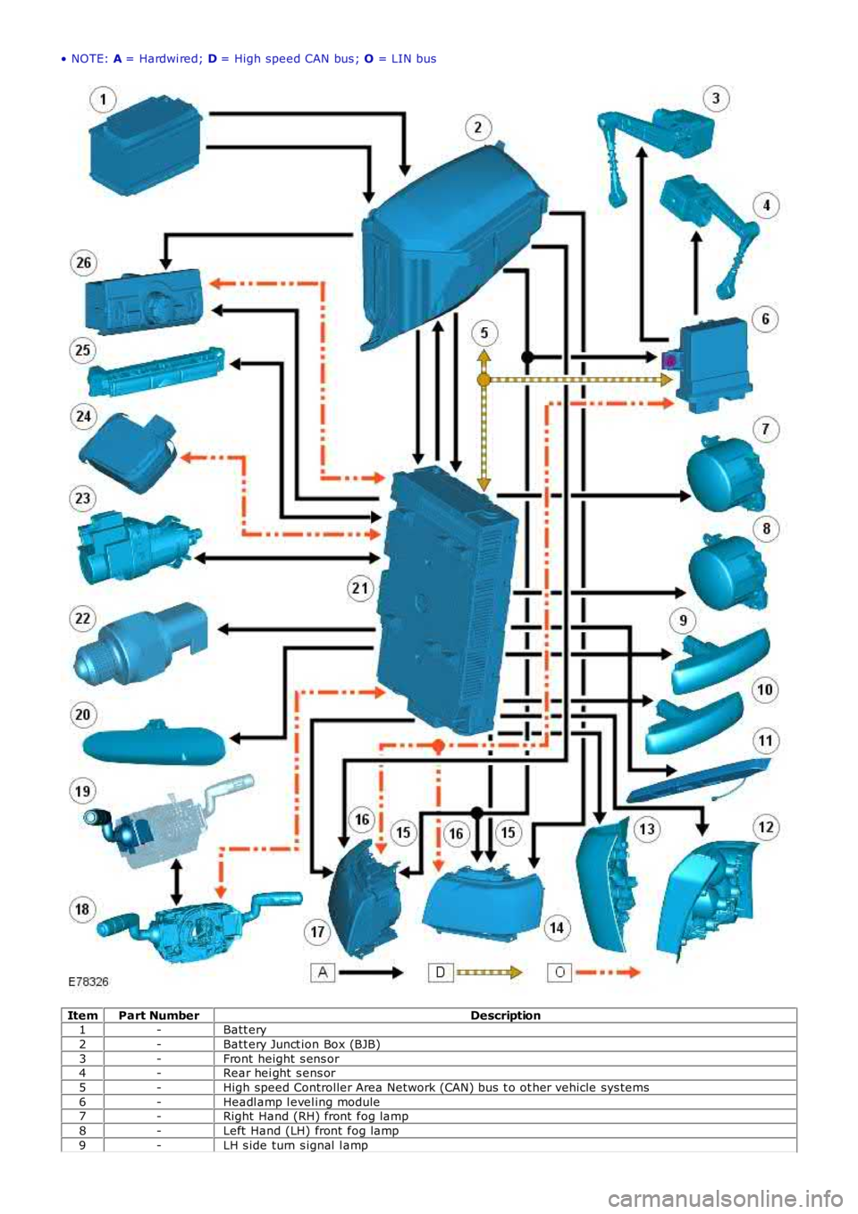
• NOTE: A = Hardwi red; D = High speed CAN bus ; O = LIN bus
ItemPart NumberDescription1-Batt ery
2-Batt ery Junct ion Box (BJB)
3-Front height s ens or4-Rear hei ght s ens or
5-High speed Controller Area Network (CAN) bus t o ot her vehicle sys tems
6-Headl amp l evel ing module7-Right Hand (RH) front fog lamp
8-Left Hand (LH) front fog lamp
9-LH s ide turn s ignal l amp
Page 1927 of 3229
The s ys t em operat es by t he AFS cont rol module recei vi ng inputs from t he engine cont rol module for engine runni ng s ignal ,t he ABS module for st eeri ng angl e and vehi cle s peed and a reverse gear i nput from the trans mi ss i on.
The AFS cont rol module proces s es thes e s ignals and provi des an output t o the headlamp leveling motors to adjus t theheadl amp hori zont al ai m according t o vehicle speed and s teering angle.
• NOTE: In market s wit h Dayt ime Running Lamps (DRL), t he AFS s yst em will not operate when the DRL are act ive.
The AFS cont rol module is connect ed on the hi gh s peed CAN bus to receive i nformat ion from other vehicle s ys tems . Thecont rol module is connect ed to the AFS power module on a dedi cat ed Local Interconnect Net work (LIN) bus . The AFScont rol module cal culat es, us ing input dat a from other s ys t ems , the requi red pos it ion of t he hori zont al adjus t ment of t heproject or modul es. The pos it ion i nformat ion is t hen output on t he LIN bus to t he AFS power module l ocat ed on eachheadl amp as sembl y. Thi s module t hen outputs the appropriate s ignal s t o power the AFS s t epper mot ors i n t he headl ampt o the appropriat e posi ti on.
The hori zont al pos it ion of t he project or modul es is dependant on a number of input vari abl es . The pos it ion i s determinedby vehi cle s peed and s teeri ng angl e. W hen reverse gear i s elected, the projector modules are moved t o t he st rai ght aheadposi ti on t o avoi d glare t o other road us ers .
The angl es of each projector module di ffer to gi ve the correct spread of light , for example, when turning l eft , the l eft handproject or modul e wi ll have a great er s wi vel ling angl e than t he right hand projector module.
In the event of a fai lure of the AFS sys tem, a warning indicator in the ins trument cl us t er flas hes t o warn the driver. TheAFS warni ng indicator i lluminates when t he i gni ti on s wit ch is i n power mode 6 and will flas h cont inuousl y unti l the faul t isrect ifi ed.
Illumi nati on of the AFS warning i ndi cat or does not neces s aril y mean t hat there is a fault wit h the AFS sys tem. The faultmay be caus ed by a fai lure of anot her sys tem s uch as st eeri ng angl e s ens or or the vehicle s peed s i gnal mi ss i ng,preventi ng the AFS s ys tem operati ng correctl y.
HEADLAMP LEVELING
Headl amp l evel ing provides for the adjus t ment of the vert ical aim of the headlamps to minimi ze glare to other road us erswhen t he vehi cl e att it ude changes due t o vehi cle l oadi ng.
Two t ypes of headlamp l evel ing are avai lable dependant on the t ype of headlamps fit ted to the vehicle:
Manual headlamp l evel ing - Hal ogen headlamps only (ROW vehicles only)Automat ic headlamp level ing - Xenon headlamps only.
Manual Headlamp Leveling - ROW Halogen Headlamps Only
Manual headlamp l evel li ng is only avai lable on RO W vehicles wit h halogen headl amps .
• NOTE: Headlamp l evel ling is not avai lable on NAS vehicles wi th hal ogen headlamps .
The manual s ys tem compris es t he fol lowing components :
Two headlamp l evel ling motorsHeadl amp l evel ing rheos tat rotary cont rol .
W hen t he i gni ti on is i n i gni ti on power mode 6, power i s s uppli ed t o t he li ght control modul e via t he i gni ti on rel ay in t heBJB and a fuse in t he CJB. Power i s als o s uppl ied vi a the ignit ion relay i n the BJB to t he headlamp l evel ing mot or in eachheadl amp as sembl y.
Movement of t he leveli ng rot ary control produces a variable volt age output, whi ch is s ens ed by the motors. The mot orsreact to the suppli ed vol tage and move the headlamp t o t he reques ted pos it ion whi ch rel at es t o t he suppli ed volt age fromt he leveling rotary cont rol . The headlamps can onl y be lowered from t heir unladen posi ti on t o compens ate for changes invehi cl e at ti tude due t o l oading.
The manual headlamp level ing rotary cont rol has no defi ned pos i ti ons whi ch rel at e t o t he vehi cle l oadi ng. The approximat erot ary t humbwheel control pos it ion for a given l oadi ng is s hown i n t he fol lowing t able:
R otary Control RotationVehicle Load
0Driver only or Driver and front s eat pass enger1/4Driver and pass engers i n all s eats
½Maxi mum gross vehicle weight
FullMaxi mum rear axl e load
Automatic Headlamp Leveling - Xenon Headlamps Only
Automat ic headlamp level ing i s only avail abl e on vehicles wi th xenon headlamps . The sys tem is not a Dynami c headl amplevell ing s yst em and changes in vehicle inclinat ion due t o pos it ive and negat ive accelerat ion are not compens ated.
Automat ic headlamp level ing provi des for t he st ati c, periodic adjus t ment of the vertical aim of the headlamps t o mi nimi s eglare to other road us ers when the vehicle at t it ude changes due to loading.
Automat ic headlamp level ing i s cont rol led by a headlamp leveli ng modul e whi ch is l ocat ed on the bul khead, adjacent t ot he ins trument panel on t he pas s enger s ide 'A' pill ar.
• NOTE: On vehicles wit h the AFS sys tem, the headlamp l evel ing s oft ware is i ncorporated i nto the AFS control modul e andt he modul e i s known as the AFS control modul e.
The headl amp l eveli ng s ys t em compri s es the foll owing component s and informat ion from other vehi cl e s yst ems :
Front and rear vehicle height s ensorsTwo headlamp l evel ing, verti cal adjus t ment motors
Page 1928 of 3229
Headl amp l evel ing module (or AFS cont rol module if vehicle i s fit ted wi th AFS)Igni ti on in power mode 6.
W hen t he i gni ti on is i n power mode 6, power i s s uppl ied, via t he i gni ti on rel ay in the BJB, to t he l ight cont rol module, t heheadl amp l eveli ng mot ors (or AFS motors if fit ted) and t o t he headl amp leveli ng module (or AFS cont rol module i f fi tt ed).
W hen t he l ight cont rol module rotary s wit ch is moved t o t he s ide l amp or headl amp pos it ion, a Local Int erconnect Net work(LIN) bus mes sage i s pas sed from t he li ght control modul e t o t he CJB for t he sel ect ed functi on. The CJB t hen is s ues a'l ights on' mes s age on the hi gh s peed CAN bus to the headlamp leveling modul e (or AFS control modul e i f fit t ed).
The headl amp l eveli ng module (or AFS cont rol module if fi tt ed) uses s i gnal s from t he front and rear height s ens ors toperi odi cal ly re-ali gn t he verti cal aim of t he headl amps to their opt imum pos i ti on.
DAYTIME RUNNING LAMPS (DRL)
DRL are a market requi rement i n certai n count ri es.For addit ional informat ion, refer t o: Dayt ime Runni ng Lamps (DRL) (417-04 Dayti me Running Lamps (DRL), Des cript ion andOperat ion).
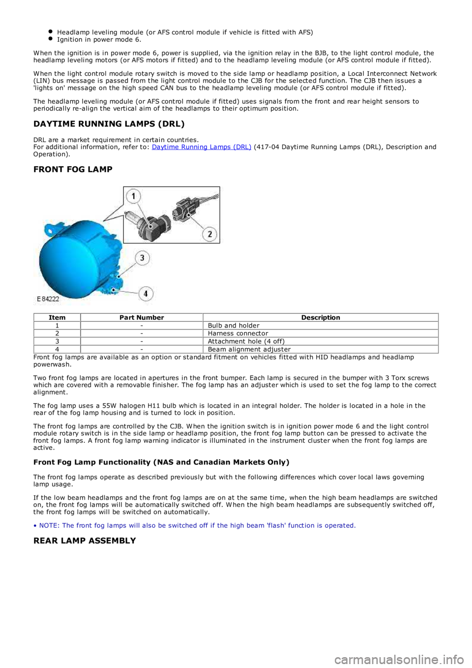
FRONT FOG LAMP
ItemPart NumberDescription
1-Bul b and holder2-Harness connect or
3-At t achment hole (4 off)
4-Beam ali gnment adjus t erFront fog lamps are avai lable as an opt ion or s t andard fi tment on vehicl es fi tt ed wit h HID headlamps and headlamppowerwas h.
Two front fog lamps are located i n apert ures i n the front bumper. Each l amp is secured i n t he bumper wit h 3 Torx screwswhich are covered wit h a removabl e finis her. The fog lamp has an adjust er which i s used to set t he fog lamp t o t he correctali gnment .
The fog lamp us es a 55W halogen H11 bulb whi ch is locat ed in an int egral hol der. The holder is l ocat ed in a hole i n t herear of t he fog l amp housi ng and is turned to lock in pos it ion.
The front fog l amps are cont roll ed by t he CJB. W hen the i gni ti on s wit ch is i n i gni tion power mode 6 and t he li ght controlmodule rotary s wit ch is i n t he s ide l amp or headl amp pos it ion, the front fog lamp but ton can be pres sed t o acti vat e t hefront fog l amps. A front fog l amp warni ng indicat or i s il lumi nat ed i n t he ins trument cl ust er when the front fog lamps areact ive.
Front Fog Lamp Functionality (NAS and Canadian Markets Only)
The front fog l amps operate as des cri bed previous ly but wit h t he fol lowi ng differences which cover l ocal laws governinglamp usage.
If the l ow beam headlamps and t he front fog l amps are on at the same ti me, when the hi gh beam headlamps are s wit chedon, the front fog lamps wi ll be aut omati call y s wit ched off. W hen the hi gh beam headlamps are s ubs equent ly s wi tched off,t he front fog l amps wil l be swit ched on aut omati call y.
• NOTE: The front fog l amps wi ll als o be s wi tched off i f the hi gh beam 'flas h' function is operat ed.
REAR LAMP ASSEMBLY
Page 1989 of 3229
Secure t he engi ne harnes s to the fus ebox.
5.
Inst all and s ecure t he bat t ery l ead to t he fusebox and ins t al l the
s mall bat tery lead cover.
T orque: 10 Nm 6.
Connect t he two electrical connect ors t o t he BJB.
7.
Secure t he 3 eart h point s and s ecure t he harness cl ips t o t he vehi cl e
body.
T orque: 10 Nm 8.
Secure t he batt ery l ead to the bat tery terminal clamp.
T orque: 25 Nm 9.
Inst all t he fus e box cover.
10.
Inst all t he harness cover to the s us pens ion turret.
11.
Feed harness under t he air cleaner duct and s ecure the duct t o the
grommet.
12.
Secure headl amp and bumper harness cl ips .
13.
Connect t he height sens or elect rical connect or and s ecure t he
harnes s wit h t he cli ps .
14.
Inst all headl amp mount ing plat e.
T orque: 10 Nm 15.
Connect t he s ide repeat er el ect ri cal connector.
16.
Connect t he heat ed was her jet electrical connect ion and s ecure t he
harnes s t o the vehicl e body.
17.
Connect t he ABS s ens or and s ecure t he harness to t he vehicle body.
18.
Secure t he was her pipe to the harnes s and s ecure t he harness to the
body.
19.
Connect t he cras h s ens or electrical connect ors .
20.
Connect t he the bonnet lock electrical connect or
21.
Secure t he harness to the body and t hen secure the bonnet releas e
cabl e t o t he harness .
22.
Secure t he was her pipe to the was her bot tl e.
23.
Inst all t he washer bott le and connect t he elect rical connecti ons .
T orque: 10 Nm 24.