Page 2223 of 3229
Publi shed: 11-May-2011
Seating - Front Seat Manual Height Adjustment LeverRemoval and Installation
Removal
1. Remove the dri vers si de seat slides.For additi onal information, refer to: Front Seat Track (501-10 Seati ng,Removal and Install ation).
2. Remove the front seat cushion base.For additi onal information, refer to: Front Seat Cushion (501-10Seating, Removal and Installation).
3.
4.
5. TORQUE: 25 Nm
Page 2224 of 3229
6. CAUTIONS:
Ti e strapsmust be fitted,fail ure to foll owthis instructionmay resul t inpersonal injury.
Fail ure tofoll ow thisinstructi on maycause damageto the vehicle.
Secure theseat baseusing the 4tie strapssuppli ed, asshown.
Usi ngthe seatheightadjuster,lowerthe seatbase toitslowestpositi on.
7. Rel ease the arm from the height adjuster.
Remove the Torx bolt.
8. Drill out the 4 ri vets.
Installation
1. To instal l, reverse the removal procedure.
Page 2244 of 3229

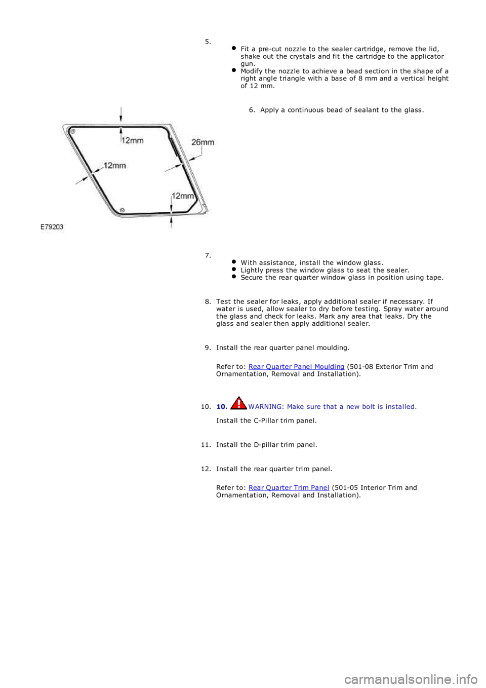
Fit a pre-cut nozzl e t o the sealer cart ri dge, remove the lid,s hake out t he crys tal s and fi t the cartridge t o t he appl icatorgun.Modify t he nozzle to achieve a bead s ecti on in the s hape of aright angl e t ri angle wit h a bas e of 8 mm and a verti cal heightof 12 mm.
5.
Apply a cont inuous bead of s ealant to the gl ass .6.
W it h ass i st ance, i ns t all the window glas s .Light ly pres s t he wi ndow glas s to seat t he s eal er.Secure t he rear quart er window glas s i n posi ti on usi ng t ape.
7.
Tes t the s ealer for l eaks , appl y addit ional s ealer i f necess ary. Ifwat er i s us ed, al low s ealer t o dry before t es ti ng. Spray wat er aroundt he glas s and check for leaks . Mark any area t hat leaks . Dry theglas s and s ealer then apply addi ti onal s eal er.
8.
Inst all t he rear quart er panel moulding.
Refer t o: Rear Quarter Panel Mouldi ng (501-08 Ext eri or Trim andOrnament ati on, Removal and Ins tal lat ion).
9.
10. W ARNING: Make sure t hat a new bolt is ins tal led.
Inst all t he C-Pi llar t ri m panel.
10.
Inst all t he D-pi llar t ri m panel.11.
Inst all t he rear quart er t ri m panel.
Refer t o: Rear Quarter Tri m Panel (501-05 Int erior Tri m andOrnament ati on, Removal and Ins tal lat ion).
12.
Page 2246 of 3229
s hake out t he crys tal s and fi t the cartridge t o t he appl icatorgun.Modify t he nozzle to achieve a bead s ecti on in the s hape of aright angl e t ri angle wit h a bas e of 8 mm and a verti cal heightof 12 mm.
Apply a cont inuous bead of s ealant to the gl ass .6.
W it h ass i st ance, i ns t all the window glas s .Light ly pres s t he wi ndow glas s to seat t he s eal er.Secure t he rear quart er window glas s i n posi ti on usi ng t ape.
7.
Tes t the s ealer for l eaks , appl y addit ional s ealer i f necess ary. Ifwat er i s us ed, al low s ealer t o dry before t es ti ng. Spray wat er aroundt he glas s and check for leaks . Mark any area t hat leaks . Dry theglas s and s ealer then apply addi ti onal s eal er.
8.
Connect t he heat ed rear wi ndow electrical connect ors .9.
Inst all t he rear window wiper motor.
Refer t o: Rear W indow W iper Motor (501-16 W i pers and W as hers ,Removal and Ins tall ati on).
10.
Page 2248 of 3229

Apply acti vat or over t he old sealant on t he wi nds hiel d glas s andall ow t o cure.4.
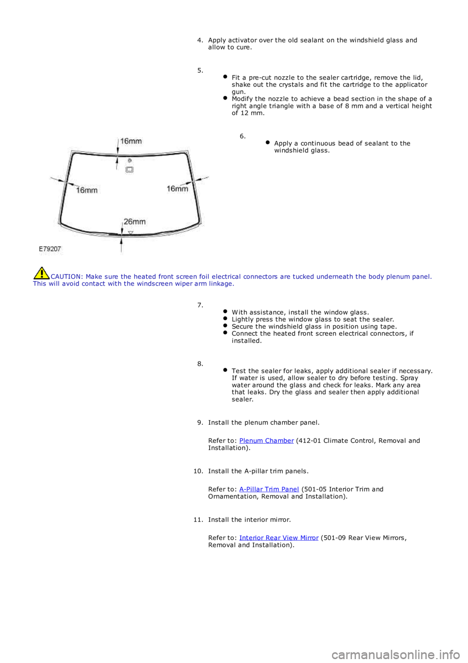
Fit a pre-cut nozzl e t o the sealer cart ri dge, remove the lid,s hake out t he crys tal s and fi t the cartridge t o t he appl icatorgun.Modify t he nozzle to achieve a bead s ecti on in the s hape of aright angl e t ri angle wit h a bas e of 8 mm and a verti cal heightof 12 mm.
5.
Apply a cont inuous bead of s ealant to thewi nds hiel d glas s.
6.
CAUTION: Make s ure the heated front s creen foil electrical connect ors are t ucked underneat h t he body plenum panel.This wi ll avoid contact wit h t he winds creen wi per arm l inkage.
W it h ass i st ance, i ns t all the window glas s .Light ly pres s t he wi ndow glas s to seat t he s eal er.Secure t he winds hield gl ass in pos it ion us ing tape.Connect t he heat ed front s creen electrical connect ors , ifi ns t alled.
7.
Tes t the s ealer for l eaks , appl y addit ional s ealer i f necess ary.If water is used, all ow s eal er to dry before t es t ing. Spraywat er around the gl as s and check for leaks . Mark any areat hat l eaks . Dry the gl ass and sealer t hen appl y addit ionals ealer.
8.
Inst all t he plenum chamber panel.
Refer t o: Plenum Chamber (412-01 Cl imat e Control, Removal andInst all at ion).
9.
Inst all t he A-pi llar t ri m panels .
Refer t o: A-Pil lar Tri m Panel (501-05 Int erior Trim andOrnament ati on, Removal and Ins tal lat ion).
10.
Inst all t he int erior mi rror.
Refer t o: Int erior Rear View Mirror (501-09 Rear Vi ew Mi rrors ,Removal and Ins tall ati on).
11.
Page 2455 of 3229

6
7
8
1
2
3
4
1
2
3
4
1
2
3
1
2
3
Confirm webbi ng gui de locati on is correct , Confirm t he fixing l ugs are correct ly locat ed i n theret ractor frame
All ow webbing t o ret ract
Check for correct operati on tw ice
Does the webbing move freel y t hen retract correctl y?YesRefer to the 501-20 removal and ins tal lati on s ect ion of t he works hop manual , rei ns t all any trimpanel s, ens ure t here are no obs truct ions and t he webbing does not cat ch or rub. No further acti onrequiredNoGO t o Pi npoint Tes t D.
PINPOINT TEST D : TWIST IN WEBBING
T ESTCO NDIT IONSDET AILS/RESULT S/ACT IONS
D1: T WIST IN WEBBINGRefer to s ect ion 501-20 removal and i nst all at ion secti on of the works hop manual , remove any t rimpanel s required to expos e t he D l oop (anchor point )Twis t t he webbi ng back t he correct way i n t he loop
Pas s t he t wis t t hrough the pi ll ar loop or escutcheon as required
Check for correct operati on tw ice
Does the webbing move freel y t hen retract correctl y?YesRefer to the 501-20 removal and ins tal lati on s ect ion of t he works hop manual , rei ns t all any trimpanel s, ens ure t here are no obs truct ions and t he webbing does not cat ch or rub. No further acti onrequiredNoGO t o Pi npoint Tes t E.
PINPOINT TEST E : INTERFERENCE-WEBBING ROUTING
T ESTCO NDIT IONSDET AILS/RESULT S/ACT IONS
E1: INT ERFERENCE-WEBBING ROUT ING
Refer to the 501-20 removal and ins tal lati on s ect ion of t he works hop manual , remove any t ri mpanel s required to expos e t he D l oop (anchor point )
Remove obs t ructi ons and forei gn objects ens ure t he webbing does not cat ch or rub
Confirm the s afet y belt does not cont act t he wiring harnes s
Check for correct operati on tw ice
Does the webbing move freel y t hen retract correctl y?YesRefer to the 501-20 removal and ins tal lati on s ect ion of t he works hop manual , rei ns t all any trimpanel s, ens ure t here are no obs truct ions and t he webbing does not cat ch or rub. No further acti onrequiredNoGO t o Pi npoint Tes t F.
PINPOINT TEST F : SAFETY BELT RETRACTOR-INCORRECT INSTALLATION
T ESTCONDIT IONSDET AILS/RESULT S/ACT IO NS
F1: SAFET Y BELT RET RACT OR-INCORRECT INST ALLAT IO N
Refer t o the 501-20 removal and ins tal lati on s ect ion of t he works hop manual, remove any t ri mpanel s required t o expos e t he D l oop (anchor poi nt ) and t he s afety bel t ret ractor
Refer t o the 501-20 removal and ins tal lati on s ect ion of t he works hop manual, correctly reins tall t hes afety bel t ret ractor ens ure t hat the l ocat ing "T bar" and "anti rot ati on pins " are correctl y located
Check for correct operati on tw ice
Does the webbing move freel y t hen ret ract correctl y?YesRefer t o the 501-20 removal and ins tal lati on s ect ion of t he works hop manual, rei nst all any t rimpanel s, ens ure t here are no obs truct ions and t he webbing does not cat ch or rub. No furt her acti onrequiredNoRepl ace as required. Refer t o t he warranty pol icy and procedures manual , or det ermine i f any priorapproval programme i s in operati on, prior to the ins tall ati on of a new module/component
PINPOINT TEST G : D-LOOP NOT ROTATING CORRECTLY
T ESTCONDIT IONSDET AILS/RESULT S/ACT IO NS
G1: D-LOOP NO T ROT AT ING CORRECT LYRefer t o the 501-20 removal and ins tal lati on s ect ion of t he works hop manual, remove any t ri mpanel s required t o expos e t he D l oop (anchor poi nt ) and t he s afety bel t ret ractorEnsure t here are no obst ructi ons and the webbi ng does not catch or rub, t he D loop (anchor poi nt )rot ates correct ly and if ins t al led t he confirm the height adjus t er operat es correctly
Check for correct operati on tw ice
Does the webbing move freel y t hen ret ract correctl y?YesRefer t o the 501-20 removal and ins tal lati on s ect ion of t he works hop manual, rei nst all any t rimpanel s, ens ure t here are no obs truct ions and t he webbing does not cat ch or rub. No furt her acti onrequiredNo
Page 2514 of 3229

ItemPart NumberDescription
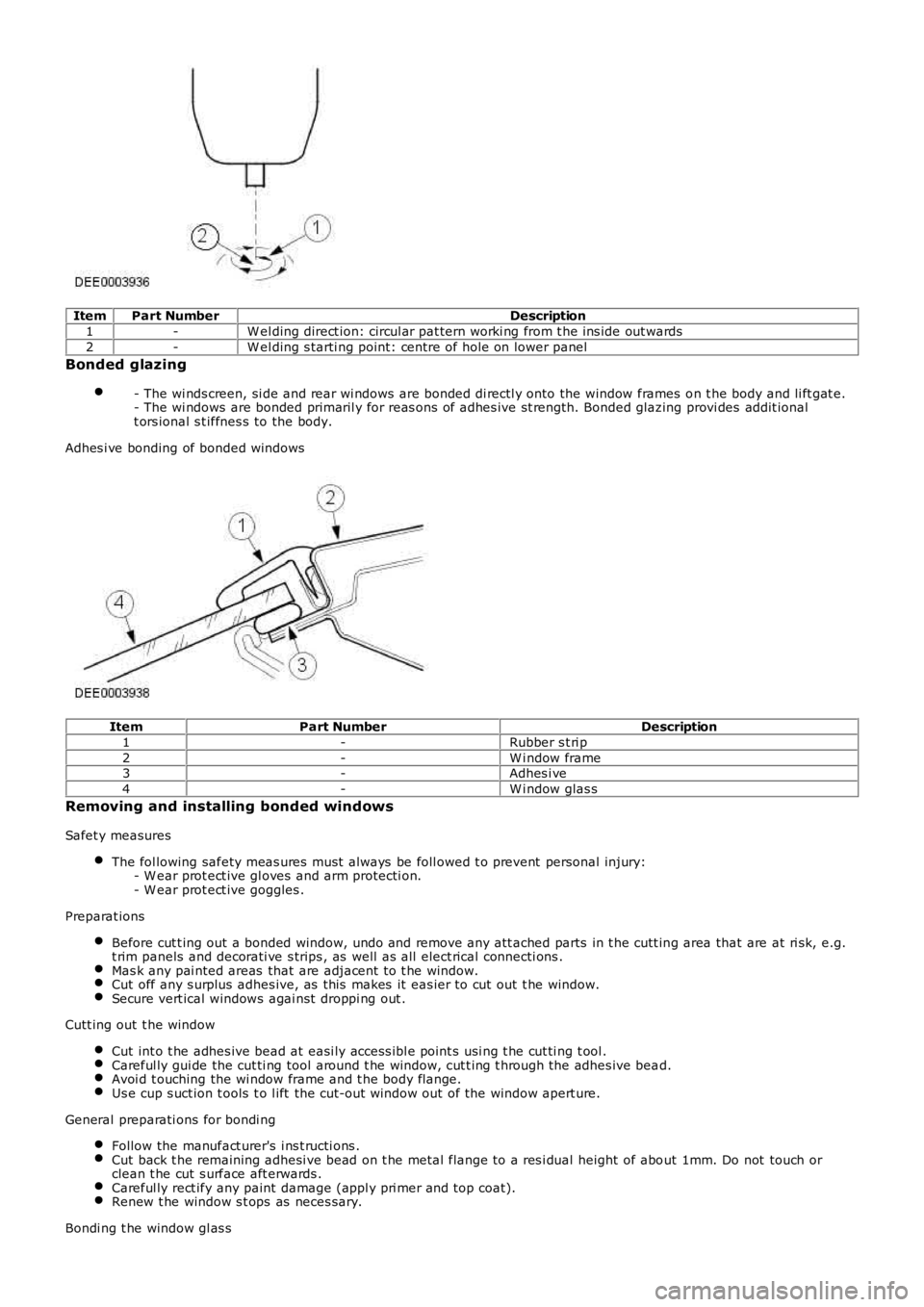
1-W el ding direct ion: circul ar pat tern worki ng from t he ins ide out wards
2-W el ding s tarti ng point: centre of hole on lower panel
Bonded glazing
- The wi nds creen, si de and rear wi ndows are bonded di rectl y onto the window frames on t he body and li ft gat e.- The wi ndows are bonded primaril y for reas ons of adhes ive st rength. Bonded glazing provi des addit ionalt ors ional s t iffnes s to the body.
Adhes i ve bonding of bonded windows
ItemPart NumberDescription
1-Rubber s t ri p
2-W i ndow frame3-Adhes i ve
4-W i ndow glas s
Removing and installing bonded windows
Safet y measures
The fol lowing safety meas ures must al ways be foll owed t o prevent personal injury:- W ear prot ect ive gl oves and arm protecti on.- W ear prot ect ive goggles .
Preparat ions
Before cut t ing out a bonded window, undo and remove any att ached parts in t he cutt ing area that are at ri sk, e.g.t rim panels and decorati ve s trips , as well as all elect rical connecti ons .Mas k any pai nted areas that are adjacent t o t he window.Cut off any s urplus adhes ive, as this makes it eas ier to cut out t he window.Secure vert ical windows agai nst droppi ng out .
Cutt ing out t he window
Cut int o t he adhes ive bead at easi ly access ibl e point s usi ng t he cut ti ng t ool .Careful ly gui de the cut ti ng tool around t he window, cut t ing t hrough the adhes ive bead.Avoi d t ouching the wi ndow frame and t he body fl ange.Us e cup s uct ion t ools t o l ift the cut-out window out of the window apert ure.
General preparati ons for bondi ng
Follow the manufact urer's i ns t ructi ons .Cut back t he remaining adhesi ve bead on t he metal flange to a res i dual height of about 1mm. Do not touch orclean t he cut s urface aft erwards .Careful ly rect ify any paint damage (appl y pri mer and top coat).Renew t he window s t ops as neces sary.
Bondi ng t he window gl as s
Page 2710 of 3229
6.
Repeat the above procedure on the opposite hand. 7.
8.
Repeat the above procedure on the opposite hand. 9.
10.
WARNING: Make sure to support the vehicle with axle
stands.
Raise and support the vehicle. 10.
Remove both rear wheels and tires.
Refer to: Wheel and Tire
(204-04 Wheels and Tires, Removal and
Installation). 11.
If installed, remove the rear suspension height sensor.
Refer to: Rear Suspension Height Sensor
(204-05 Vehi cl e Dynami c
Suspension, Removal and Installation). 12.
Remove the rear muffler.
Refer to: Exhaus t Sys t em
(309-00B Exhaus t Sys t em - TD4 2.2L
Diesel, Removal and Installation). 13.