2006 LAND ROVER FRELANDER 2 height
[x] Cancel search: heightPage 175 of 3229
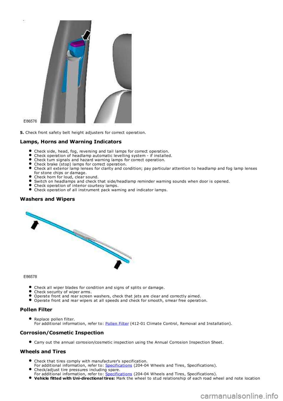
5. Check front s afet y belt height adjus ters for correct operat ion.
Lamps, Horns and Warning Indicators
Check s i de, head, fog, revers ing and tail l amps for correct operat ion.Check operat ion of headlamp aut omati c levelli ng s yst em - if ins t al led.Check t urn si gnal s and hazard warni ng lamps for correct operati on.Check brake (s t op) l amps for correct operat ion.Check al l ext eri or l amp l ens es for cl arit y and condi ti on; pay parti cular at tent ion to headl amp and fog lamp lens esfor s t one chi ps or damage.Check horn for l oud, clear s ound.Swit ch on headl amps and check t hat si de/headl amp reminder warning s ounds when door is opened.Check operat ion of i nteri or courtes y lamps .Check operat ion of al l i nst rument pack warni ng and indicator l amps.
Washers and Wipers
Check al l wiper blades for condi ti on and s igns of s pl it s or damage.Check s ecurit y of wi per arms .Operat e front and rear s creen washers, check that jet s are cl ear and correctl y aimed.Operat e front and rear wipers at all s peeds and check for s moot h, s mear free operation.
Pollen Filter
Replace pol len fil ter.For addit ional informat ion, refer t o: Pollen Fi lt er (412-01 Cl imat e Control, Removal and Ins tall ati on).
Corrosion/Cosmetic Inspection
Carry out the annual corros ion/cos meti c ins pect ion us ing t he Annual Corros ion Inspecti on Sheet .
Wheels and Tires
Check t hat ti res comply wit h manufacturer's specificati on.For addit ional informat ion, refer t o: Specificati ons (204-04 W heels and Tires , Specificati ons ).Check/adjust t ire pres s ures i ncl udi ng s pare.For addit ional informat ion, refer t o: Specificati ons (204-04 W heels and Tires , Specificati ons ).Vehicle fitted with Uni-directional tires: Mark t he wheel to st ud rel ati ons hip of each road wheel and note locat ion
Page 186 of 3229
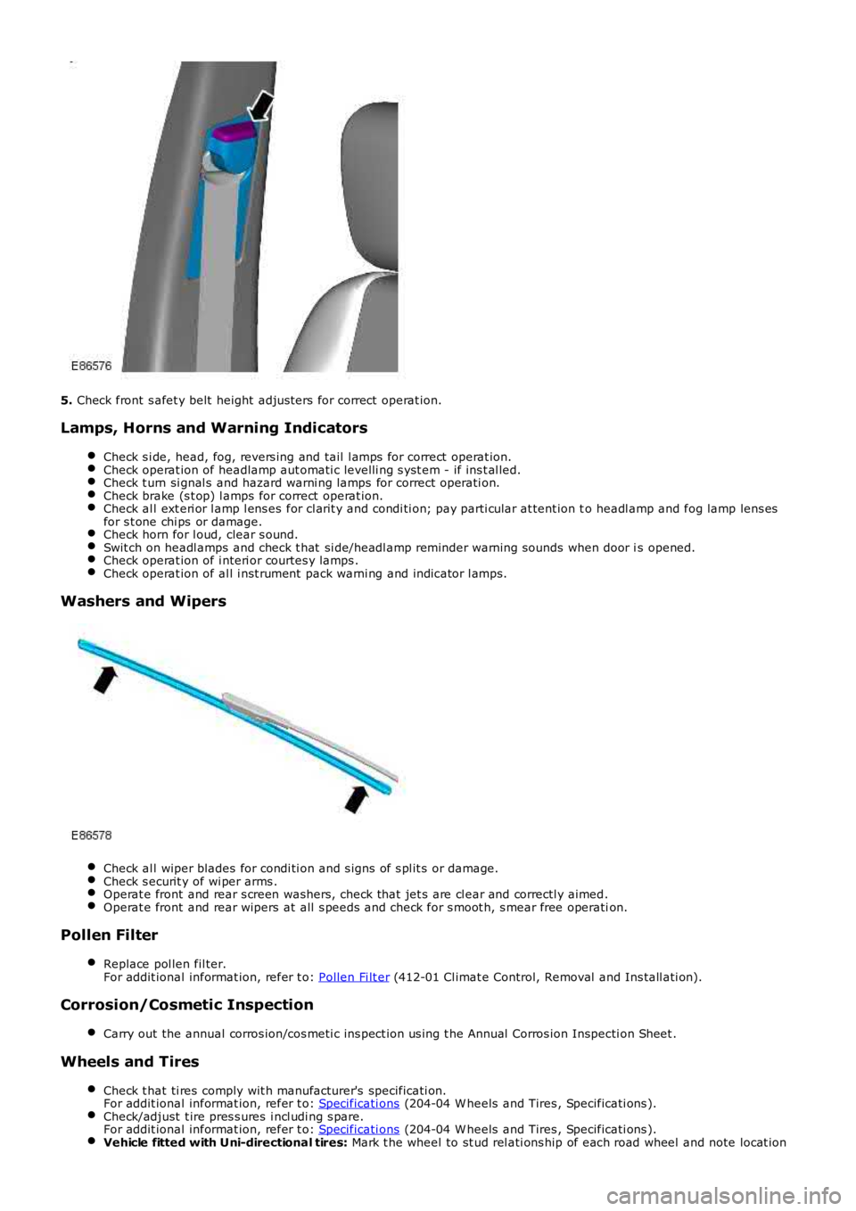
5.
Check front s afet y belt height adjus ters for correct operat ion.
Lamps, Horns and Warning Indicators Check s i de, head, fog, revers ing and tail l amps for correct operat ion. Check operat ion of headlamp aut omati c levelli ng s yst em - if ins t al led.
Check t urn si gnal s and hazard warni ng lamps for correct operati on.
Check brake (s t op) l amps for correct operat ion.
Check al l ext eri or l amp l ens es for cl arit y and condi ti on; pay parti cular at tent ion t
o headl amp and fog lamp lens es
for s t one chi ps or damage. Check horn for l oud, clear s ound.
Swit ch on headl amps and check t hat si de/headl amp reminder warning s ounds when door i
s opened.Check operat ion of i nteri or courtes y lamps .
Check operat ion of al l i nst rument pack warni ng and indicator l amps.
Washers and Wipers
Check al l wiper blades for condi ti on and s igns of s pl it s or damage.
Check s ecurit y of wi per arms .
Operat e front and rear s creen washers, check that jet s are cl ear and correctl y aimed
.Operat e front and rear wipers at all s peeds and check for s moot h, s mear free operati
on.Pollen Filter
Replace pol len fil ter.
For addit ional informat ion, refer t o: Pollen Fi lt er (412-01 Cl imat e Control, Removal and Ins tall ati on).
Corrosion/Cosmetic Inspection
Carry out the annual corros ion/cos meti c ins pect ion us ing t he Annual Corros ion Inspec ti on Sheet .Wheels and Tires
Check t hat ti res comply wit h manufacturer's specificati on.
For addit ional informat ion, refer t o: Specificati ons (204-04 W heels and Tires , Specificati ons ).
Check/adjust t ire pres s ures i ncl udi ng s pare.
For addit ional informat ion, refer t o: Specificati ons (204-04 W heels and Tires , Specificati ons ).
Vehicle fitted with Uni-directional tires:
Mark t he wheel to st ud rel ati ons hip of each road wheel and note locat ion
Page 194 of 3229
Publ is hed: 08-Dec-2011
Suspension System - General Information -
C oil Spring SuspensionItemSpecification
FrontFront: - Convent ional coi l spring wi th a t win tube damper and a high s t res s s tabi lizer bar
RearRear: - Convent ional coil s pri ng wit h a twi n t ube damper and a hi gh s tress st abil izer bar
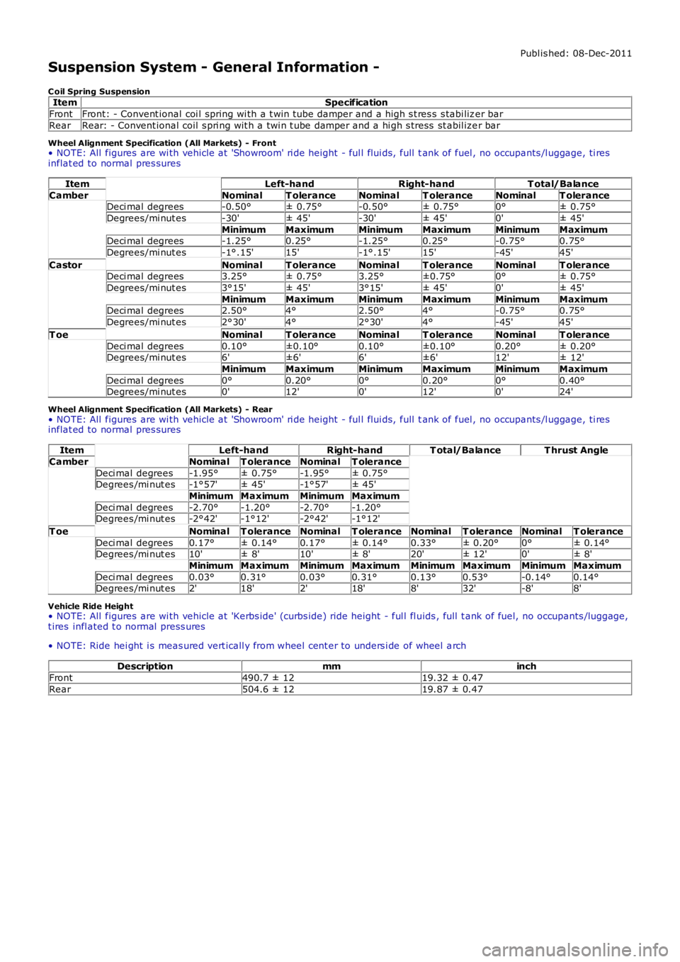
Wheel Alignment Specification (All Markets) - Front• NOTE: All figures are wi th vehicle at 'Showroom' ri de height - ful l flui ds, full tank of fuel , no occupants /l uggage, ti resinflat ed to normal pres sures
ItemLeft-handRight-handT otal/Balance
CamberNominalT oleranceNominalT oleranceNominalT oleranceDeci mal degrees-0.50°± 0.75°-0.50°± 0.75°0°± 0.75°
Degrees/mi nut es-30'± 45'-30'± 45'0'± 45'
MinimumMaximumMinimumMaximumMinimumMaximumDeci mal degrees-1.25°0.25°-1.25°0.25°-0.75°0.75°
Degrees/mi nut es-1°.15'15'-1°.15'15'-45'45'
CastorNominalT oleranceNominalT oleranceNominalT oleranceDeci mal degrees3.25°± 0.75°3.25°±0.75°0°± 0.75°
Degrees/mi nut es3°15'± 45'3°15'± 45'0'± 45'
MinimumMaximumMinimumMaximumMinimumMaximumDeci mal degrees2.50°4°2.50°4°-0.75°0.75°
Degrees/mi nut es2°30'4°2°30'4°-45'45'
T oeNominalT oleranceNominalT oleranceNominalT olerance
Deci mal degrees0.10°±0.10°0.10°±0.10°0.20°± 0.20°Degrees/mi nut es6'±6'6'±6'12'± 12'
MinimumMaximumMinimumMaximumMinimumMaximum
Deci mal degrees0°0.20°0°0.20°0°0.40°Degrees/mi nut es0'12'0'12'0'24'
Wheel Alignment Specification (All Markets) - Rear• NOTE: All figures are wi th vehicle at 'Showroom' ri de height - ful l flui ds, full tank of fuel , no occupants /l uggage, ti resinflat ed to normal pres sures
ItemLeft-handRight-handT otal/BalanceT hrust Angle
CamberNominalT oleranceNominalT olerance
Deci mal degrees-1.95°± 0.75°-1.95°± 0.75°Degrees /mi nut es-1°57'± 45'-1°57'± 45'
MinimumMaximumMinimumMaximum
Deci mal degrees-2.70°-1.20°-2.70°-1.20°Degrees /mi nut es-2°42'-1°12'-2°42'-1°12'
T oeNominalT oleranceNominalT oleranceNominalT oleranceNominalT olerance
Deci mal degrees0.17°± 0.14°0.17°± 0.14°0.33°± 0.20°0°± 0.14°Degrees /mi nut es10'± 8'10'± 8'20'± 12'0'± 8'
MinimumMaximumMinimumMaximumMinimumMaximumMinimumMaximum
Deci mal degrees0.03°0.31°0.03°0.31°0.13°0.53°-0.14°0.14°Degrees /mi nut es2'18'2'18'8'32'-8'8'
Vehicle Ride Height• NOTE: All figures are wi th vehicle at 'Kerbs ide' (curbs ide) ride height - ful l fl uids , full t ank of fuel, no occupants /luggage,t ires infl ated t o normal press ures
• NOTE: Ride hei ght i s meas ured vert icall y from wheel cent er to unders i de of wheel arch
Descriptionmminch
Front490.7 ± 1219.32 ± 0.47
Rear504.6 ± 1219.87 ± 0.47
Page 198 of 3229
Publi s hed: 11-May-2011
Front Suspension -
C oil Spring SuspensionItemSpecification
FrontConvent ional coil s pri ng wi th a twi n t ube damper and a high s tres s s tabil izer bar
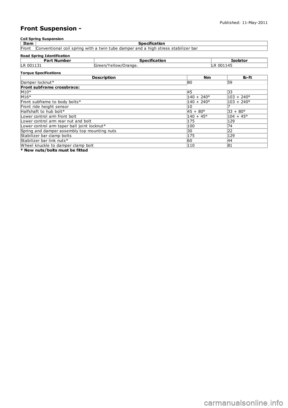
Road Spring Identification
Part NumberSpecificationIsolator
LR 001131Green/Y ell ow/Orange.LR 001145
Torque SpecificationsDescriptionNmlb-ft
Damper locknut *8059
Front subframe crossbrace:M10*4533
M16*140 + 240°103 + 240°
Front s ubframe t o body bol ts *140 + 240°103 + 240°Front ride height s ens or107
Halfs haft to hub bol t*45 + 80°33 + 80°
Lower cont rol arm front bol t140 + 45°104 + 45°Lower cont rol arm rear nut and bol t175129
Lower cont rol arm taper ball joi nt locknut *10074
Spri ng and damper as s embly t op mounti ng nuts3022St abi lizer bar cl amp bolt s175129
St abi lizer bar li nk nut s *6044
W heel knuckle to damper clamp bol t11081* New nuts/bolts must be fitted
Page 200 of 3229
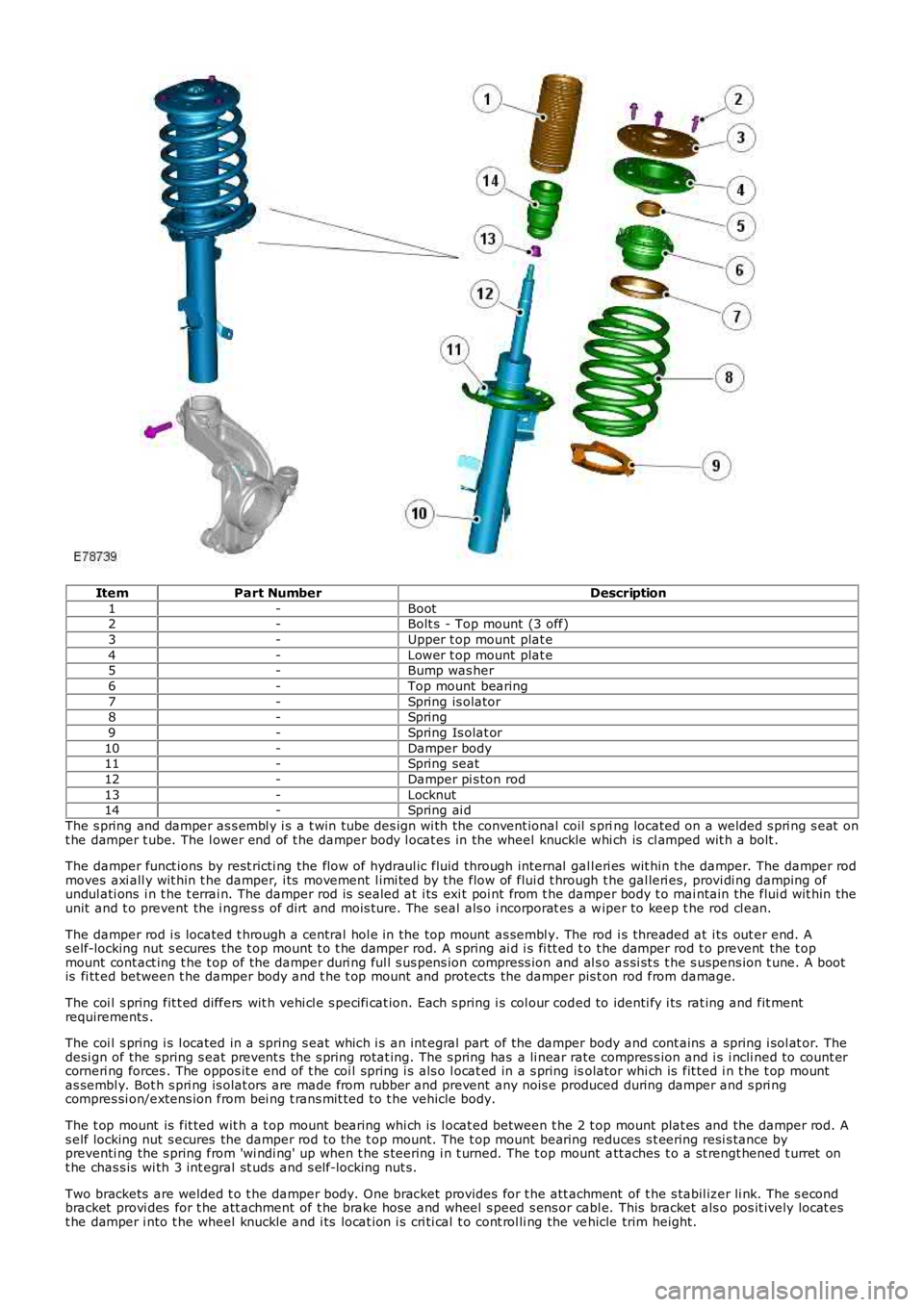
ItemPart NumberDescription
1-Boot2-Bolt s - Top mount (3 off)
3-Upper t op mount plat e
4-Lower t op mount plat e5-Bump was her
6-Top mount bearing
7-Spring is olator8-Spring
9-Spring Is olat or
10-Damper body11-Spring seat
12-Damper pi s ton rod
13-Locknut14-Spring ai d
The s pring and damper as s embl y i s a t win tube des ign wi th the convent ional coil s pring located on a welded s pri ng s eat ont he damper t ube. The l ower end of t he damper body l ocat es in the wheel knuckle whi ch is cl amped wit h a bolt .
The damper funct ions by rest ricti ng the flow of hydraul ic fluid through internal gall eri es wit hin t he damper. The damper rodmoves axi all y wit hin t he damper, i ts movement l imi ted by the flow of flui d t hrough the gal leri es, provi di ng damping ofundul ati ons i n t he t errai n. The damper rod is s ealed at i ts exi t poi nt from t he damper body t o mai ntain the flui d wit hin theunit and t o prevent the i ngres s of dirt and mois ture. The seal als o i ncorporat es a wiper to keep t he rod cl ean.
The damper rod i s located t hrough a central hol e in the top mount as sembl y. The rod i s threaded at i ts out er end. As elf-locking nut s ecures the t op mount t o t he damper rod. A s pring ai d i s fi tt ed t o t he damper rod t o prevent the t opmount cont act ing t he t op of the damper duri ng ful l s us pens ion compress ion and al s o as si st s t he s uspens ion t une. A bootis fi tt ed between t he damper body and t he t op mount and protects the damper pis t on rod from damage.
The coi l s pring fit t ed differs wit h vehi cl e s peci fi cat ion. Each s pring i s col our coded to identi fy i ts rat ing and fit mentrequirements .
The coi l s pring i s l ocated in a spring s eat which i s an int egral part of the damper body and cont ains a spring i sol at or. Thedesi gn of the spring s eat prevent s t he s pring rotat ing. The s pring has a li near rate compres s ion and i s i ncli ned to count ercorneri ng forces . The oppos it e end of t he coi l spring i s als o l ocat ed in a s pring isolator whi ch is fit ted i n t he t op mountas sembl y. Bot h s pri ng is olat ors are made from rubber and prevent any nois e produced during damper and s pri ngcompres si on/extens ion from bei ng t rans mit ted to t he vehicle body.
The t op mount is fit ted wit h a t op mount bearing whi ch is l ocat ed between t he 2 t op mount plat es and the damper rod. As elf locking nut s ecures the damper rod to the t op mount. The t op mount bearing reduces s t eering resi s tance bypreventi ng the s pring from 'wi ndi ng' up when t he s teering i n t urned. The t op mount att aches t o a st rengt hened t urret ont he chas s is wi th 3 int egral st uds and s elf-locking nut s.
Two brackets are welded t o t he damper body. One bracket provides for t he att achment of t he s tabil izer li nk. The s econdbracket provi des for t he att achment of t he brake hose and wheel s peed s ens or cabl e. This bracket als o pos it ively locat est he damper i nto t he wheel knuckle and i ts locat ion i s cri ti cal t o cont rol li ng the vehicle trim height.
Page 203 of 3229
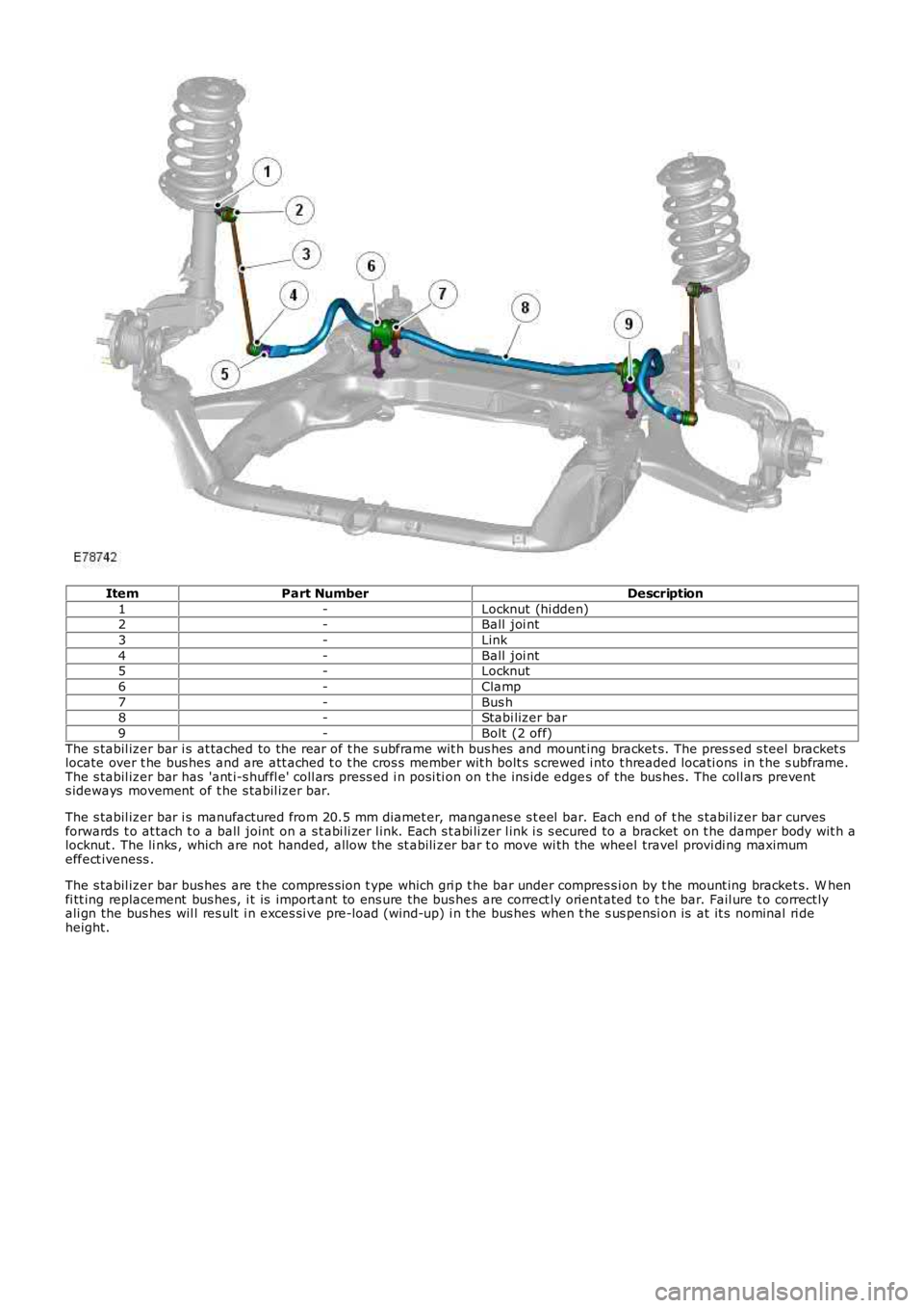
ItemPart NumberDescription
1-Locknut (hi dden)2-Ball joi nt
3-Link
4-Ball joi nt5-Locknut
6-Clamp
7-Bus h8-Stabi lizer bar
9-Bolt (2 off)
The s tabil izer bar i s at tached to the rear of t he s ubframe wit h bus hes and mount ing bracket s. The pres s ed s teel bracket slocate over t he bus hes and are att ached t o t he cros s member wit h bolt s s crewed i nto t hreaded locati ons in t he s ubframe.The s tabil izer bar has 'ant i-s huffl e' coll ars press ed i n posi ti on on t he ins ide edges of the bus hes. The coll ars prevents ideways movement of t he s tabil izer bar.
The s tabil izer bar i s manufactured from 20.5 mm diamet er, manganes e s t eel bar. Each end of t he s tabil izer bar curvesforwards t o at tach t o a ball joint on a s t abi li zer l ink. Each s t abi li zer l ink i s s ecured to a bracket on t he damper body wit h alocknut . The li nks , which are not handed, allow the st abili zer bar t o move wi th the wheel travel provi di ng maximumeffect iveness .
The s tabil izer bar bus hes are t he compres s ion t ype which gri p t he bar under compres si on by t he mount ing bracket s. W henfi tt ing replacement bus hes, i t is import ant to ens ure the bus hes are correct ly orient ated t o t he bar. Fail ure t o correct lyali gn the bus hes wil l res ult i n exces si ve pre-load (wind-up) i n t he bus hes when t he s us pensi on is at it s nominal ri deheight.
Page 230 of 3229
Publi s hed: 11-May-2011
Rear Suspension -
C oil Spring SuspensionItemSpecification
RearConvent ional coil s pri ng wi th a twi n t ube damper and a high s tres s s tabil izer bar
Road Spring C olor C oding - Rear
Part NumberSpring ColorIsolator
RKB 500210GreyLR 003092 (9mm)RKB 500210Grey/W hit eLR 005304 (15mm)
RKB 500220BrownLRL 003092 (9mm)
RKB 500220Brown/W hi teLR 005304 (15mm)• NOTE: The grey or brown s prings have a 9 mm thi ck i s ol ator
• NOTE: The grey/whi te or brown/whi te springs have a 15 mm t hick is olat or
To mai nt ain correct trim height make s ure t he s pri ng col our and appropriate is olat or i s mat ched
Torque SpecificationsDescriptionNmlb-ft
Damper locknut8059
Front l ower arm t rans vers e li nks nut s & bol ts175129Rear ri de hei ght sens or107
Rear lower arm nuts & bolt s175129
Spri ng and damper as s embly t op mounti ng nuts3224St abi lizer bar bus hing cl amp bolt s*6044
St abi lizer li nk nuts *6044
Trai li ng arm nut s and bolt s270199Trai li ng arm bracket t o body bolt s*11081
W heel knuckle to damper clamp bol t11081
* New nuts/bolts must be fitted
Page 233 of 3229
The t op mount at t aches t o a s t rengthened turret on t he chas s is wit h 3 i ntegral s tuds and s elf-l ocking nut s .
Two brackets are welded t o t he damper body. One bracket provides for t he att achment of t he s tabil izer li nk. The s econdbracket provi des for t he att achment of t he brake hose and wheel s peed s ens or cabl e. This bracket als o pos it ively locat est he damper i nto t he wheel knuckle and i ts locat ion i s cri ti cal t o cont rol li ng the vehicle trim height.
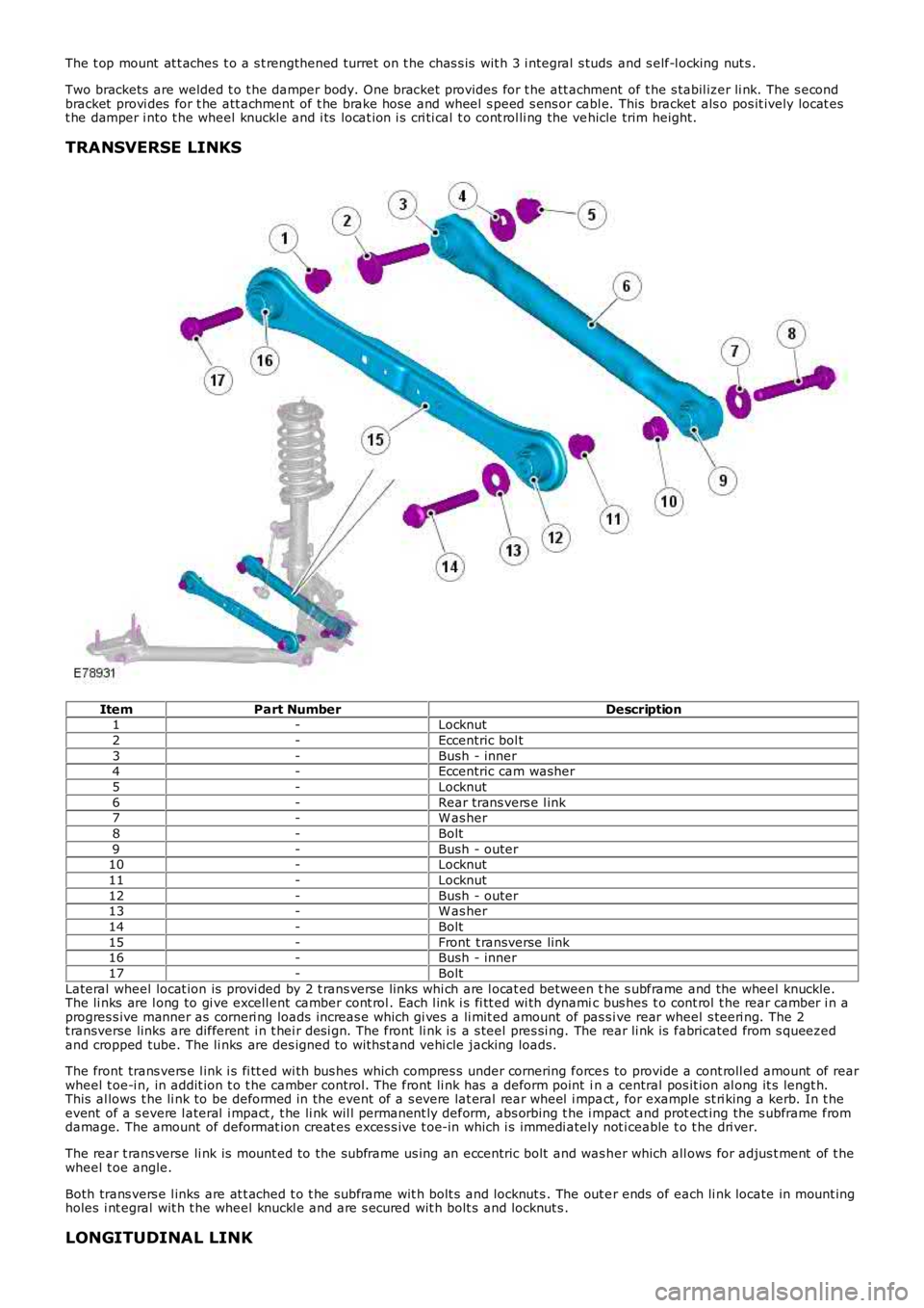
TRANSVERSE LINKS
ItemPart NumberDescription1-Locknut
2-Eccentric bol t
3-Bush - inner4-Eccentric cam washer
5-Locknut
6-Rear trans vers e l ink7-W as her
8-Bolt
9-Bush - outer10-Locknut
11-Locknut
12-Bush - outer13-W as her
14-Bolt
15-Front t ransverse link16-Bush - inner
17-Bolt
Lateral wheel locat ion is provi ded by 2 t rans verse li nks whi ch are l ocat ed between the s ubframe and the wheel knuckle.The li nks are l ong to gi ve excell ent camber cont rol . Each l ink i s fi tt ed wi th dynamic bus hes t o cont rol t he rear camber i n aprogres s ive manner as corneri ng loads increas e which gi ves a li mit ed amount of pas s ive rear wheel s teeri ng. The 2t ransverse links are different i n t hei r des i gn. The front li nk is a s teel pres si ng. The rear li nk is fabricated from s queezedand cropped tube. The li nks are des igned to wit hst and vehi cle jacking loads.
The front trans vers e l ink i s fi tt ed wi th bus hes which compres s under cornering forces to provide a cont roll ed amount of rearwheel t oe-i n, in addit ion t o t he camber control. The front li nk has a deform point in a central pos it ion al ong it s lengt h.This al lows t he li nk to be deformed in the event of a s evere lat eral rear wheel i mpact , for example st ri king a kerb. In t heevent of a s evere l ateral i mpact , t he li nk wil l permanent ly deform, abs orbing t he i mpact and prot ect ing the s ubframe fromdamage. The amount of deformat ion creat es exces s ive t oe-in which i s immedi ately not iceable t o t he dri ver.
The rear t rans verse li nk is mount ed to the subframe us ing an eccentric bolt and was her which all ows for adjus t ment of t hewheel t oe angle.
Both trans vers e l inks are at t ached t o t he s ubframe wit h bolt s and locknut s . The out er ends of each li nk locate in mount ingholes i nt egral wit h t he wheel knuckl e and are s ecured wit h bolt s and locknut s .
LONGITUDINAL LINK