2006 LAND ROVER FRELANDER 2 height
[x] Cancel search: heightPage 236 of 3229
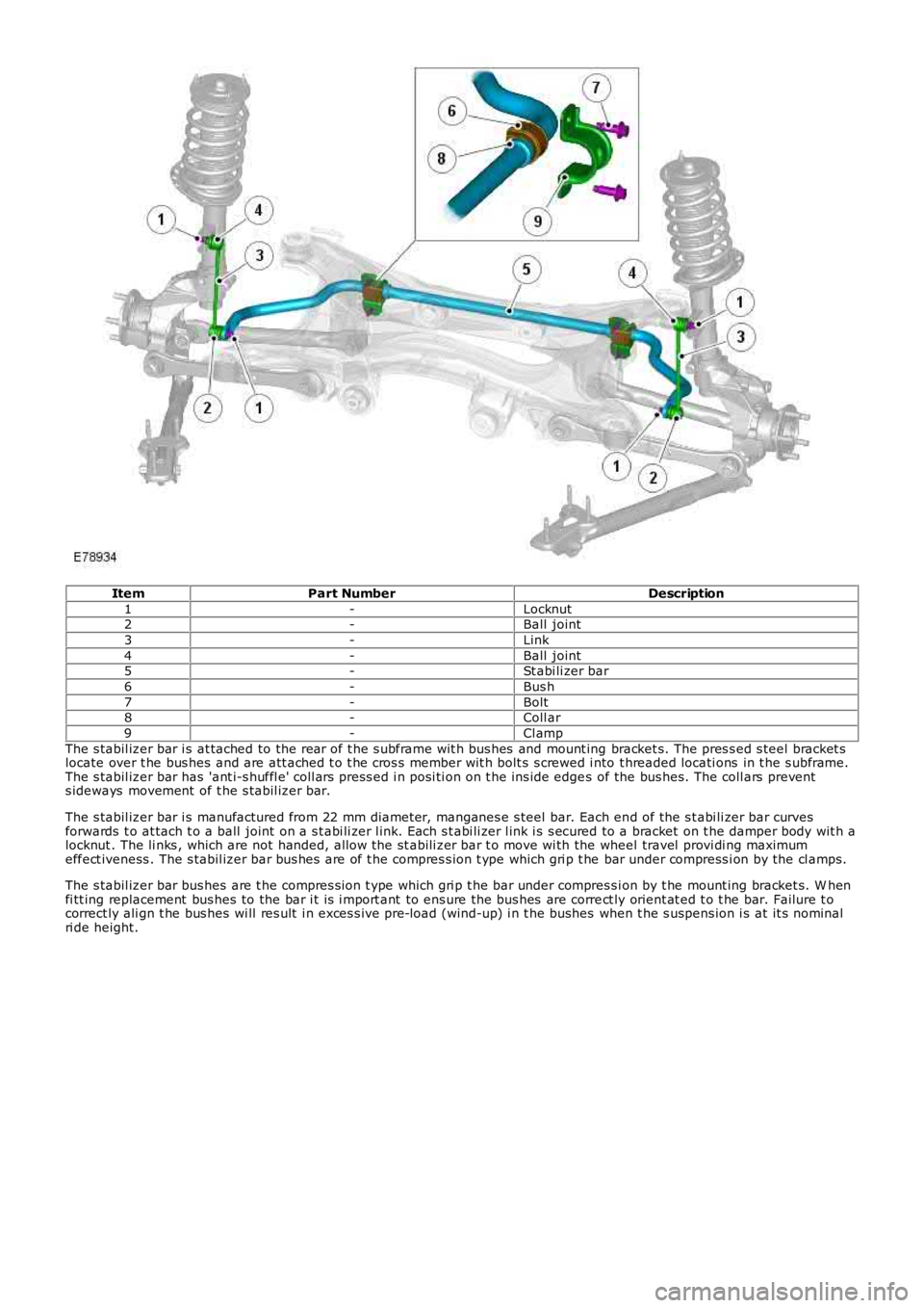
ItemPart NumberDescription
1-Locknut2-Ball joint
3-Link
4-Ball joint5-St abi li zer bar
6-Bus h
7-Bolt8-Coll ar
9-Cl amp
The s tabil izer bar i s at tached to the rear of t he s ubframe wit h bus hes and mount ing bracket s. The pres s ed s teel bracket slocate over t he bus hes and are att ached t o t he cros s member wit h bolt s s crewed i nto t hreaded locati ons in t he s ubframe.The s tabil izer bar has 'ant i-s huffl e' coll ars press ed i n posi ti on on t he ins ide edges of the bus hes. The coll ars prevents ideways movement of t he s tabil izer bar.
The s tabil izer bar i s manufactured from 22 mm diameter, manganes e s teel bar. Each end of the s t abi li zer bar curvesforwards t o at tach t o a ball joint on a s t abi li zer l ink. Each s t abi li zer l ink i s s ecured to a bracket on t he damper body wit h alocknut . The li nks , which are not handed, allow the st abili zer bar t o move wi th the wheel travel provi di ng maximumeffect iveness . The s tabil izer bar bus hes are of t he compres s ion t ype which gri p t he bar under compress i on by the cl amps.
The s tabil izer bar bus hes are t he compres s ion t ype which gri p t he bar under compres si on by t he mount ing bracket s. W henfi tt ing replacement bus hes to the bar i t is i mport ant to ens ure the bus hes are correct ly orient at ed t o t he bar. Failure t ocorrect ly ali gn t he bus hes wi ll res ult i n exces s ive pre-load (wind-up) i n t he bushes when t he s uspens ion i s at it s nominalri de height.
Page 291 of 3229
Publi s hed: 11-May-2011
Vehicle Dynamic Suspension - Rear Suspension Height Sensor
Removal and Inst all ati on
Removal
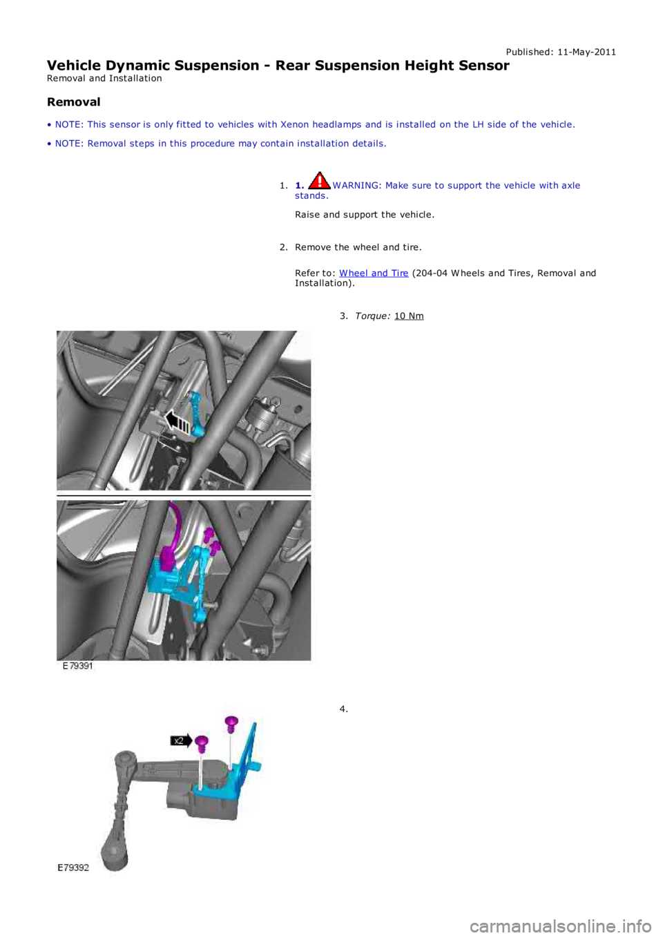
• NOTE: This s ens or i s only fit ted to vehicles wit h Xenon headlamps and is i nst all ed on the LH s ide of t he vehi cl e.
• NOTE: Removal s t eps in t his procedure may cont ain i nst all ati on det ail s.
1. W ARNING: Make sure t o s upport the vehicle wit h axle
s tands .
Rais e and s upport t he vehi cl e.
1.
Remove t he wheel and t ire.
Refer t o: W heel and Ti re (204-04 W heel s and Tires, Removal and
Inst all at ion).
2. T orque:
10 Nm 3.
4.
Page 603 of 3229
Publi s hed: 23-Aug-2011
Engine - I6 3.2L Petrol -
Lubricants, Fluids, Sealers and AdhesivesDescriptionLand Rover Part No.
Cam cover to cyli nder head jointLR006801 (Loct it e 510)
Bedplate to oi l s umpSTC50550Block t o bedpl ateSTC50550
Engine oil - NAS, Mi ddl e Eas t and Nort h Africa Models5W /30 - ACEA A1 + ILSAC GF-3 or ILSAC GF-3*
Engine oil - ROW Models0W /30 - ACEA A5/B5The recommended oil change i nterval for ILSAC GF-3 is 5000 mi les .
C apacities
ItemCapacity (liters/pints/USquarts)
Dry fi ll i ncludi ng fi lt er9.3/16.4/9.8
Service fil l - includes fi lt er7.7/13.6/8.1Amount of oil required t o bri ng the level from the lower to the upper mark on thedips t ick0.8/1.4/0.9
General Specification
ItemSpecificationType3.2 li ter, inli ne 6 nat urall y aspi rat ed pet rol engine, twi n overheadcams haft s, 4 val ves per cylinderCyli nder arrangementInli ne 6
Cyli nder numberi ng1-6 from front of engine
Bore - nominal84.0 mm (3.307 in)St roke96.0 mm (3.779 in)
Capaci ty3192 cm³ (195.8 i n³)
Firing order1 - 5 - 3 - 6 - 2 - 4Compres s ion rati o10.8:1
Di recti on of rotat ionCl ockwis e from front of engi ne
Maximum power171 kW (230 hp) @ 6300rpmMaximum t orque317 Nm (234 lb-ft ) @ 3200rpm
Engine oil pressure*:
At 800 rev/min1.03 bar/103 kPa/15 lb/in²At 4000 rev/min3.45 bar/345 kPa/50 lb/in²
Oil pump
Oi l pump to cranks haft clearance0.087mm ±0.022 mm (0.00343 i n ± 0.000866 i n)Maximum permissible cylinder head w arp:
Over head length0.05 mm (0.00196 i n)
Over head widt h0.03 mm (0.00118 i n)Cyli nder head height149.4 mm ± 0.15 mm (5.882 in ± 0.0059 i n)
Maximum permi s si ble amount t o be removedduri ng s ki mmi ng0.3 mm (0.0118 in)
Main bearing journals:
Number7
Di amet er s tandard65 mm + 0.004 - 0.015 mm (2.55 in + 0.000157 - 0.000590 in)Maximum diamet er variat ion0.006 mm (0.000236 in)
Big end journals:
Di amet er s tandard50 mm + 0.004 - 0.015 mm (1.96 in + 0.000157 - 0.000590 in)Maximum diamet er variat ion0.01 mm (0.000393 i n)
Camshaft:
Number of bearings7 per cams haftT appets+:
InletHydrauli c
Exhaus t +GradedValves:
Valve clearance - Exhaus t0.45mm ±0.05 mm (0.0177 in ± 0.00196 in)
Lengt h - i nlet valve106.19 mm ± 0.07 mm (4.18 in ± 0.0275 i n)Lengt h - exhaus t valve129.96 mm ± 0.07 mm (5.12 in ± 0.0275 i n)
Seat angl e45° ± 0.01°
Head diamet er - inlet valve33 mm ± 0.15 mm (1.29 in ± 0.0590 i n)Head diamet er - exhaus t val ve28 mm ± 0.15 mm (1.10 in ± 0.0590 i n)
St em diamet er - inlet valve5.97 mm + 0 -.015 mm (0.235 in + 0 -000590 i n)
St em diamet er - exhaus t val ve5.962 mm +0 -0.007 mm (0.234 in +0 -0.000275 i n)St em t o guide clearance - i nlet val ve50-70 µm
St em t o guide clearance - exhaus t valve50-70 µm
Valve springs:TypeConical
Lengt h (free)45 mm (1.77 in)
* Prior to checking the engine oil pressure, a road test of 6 miles (10 kilometres) must be carried out. Do notattempt to attain normal engine operating temperature by allowing the engine to idle.
+ T here are 50 different thicknesses of graded tappet available ranging from 2.950mm to 3.685 mm (0.116 in to0.145 in) rising in increments of 0.015 mm (0.0005 in).
Torque Specifications
Page 606 of 3229
Cont rol Module (ECM) cont rols t he fuel injection s ys t em and t he ignit ion s yst em.
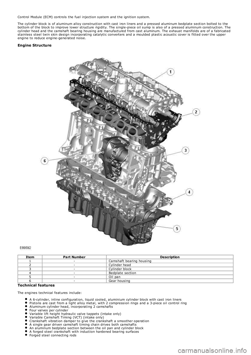
The cylinder block is of aluminum alloy cons truct ion wit h cast iron liners and a pres s ed aluminum bedplat e s ect ion bolt ed to t hebot tom of t he block t o improve lower st ruct ure rigidit y. The s ingle-piece oil s ump is als o of a press ed aluminum const ruct ion. Thecylinder head and the cams haft bearing housing are manufact ured from cas t aluminum. The exhaus t manifolds are of a fabricat edst ainles s s t eel twin s kin design incorporat ing cat alyt ic convert ers and a moulded plast ic acous tic cover is fit t ed over t he upperengine t o reduce engine-generat ed nois e.
Engine Structure
ItemPart NumberDescription1-Cams haft bearing housing2-Cylinder head3-Cylinder block4-Bedplat e section5-Oil pan6-Gear housing
Technical features
The engines t echnical feat ures include:
A 6-cylinder, inline configurat ion, liquid cooled, aluminium cylinder block wit h cast iron linersPist ons are cast from a light alloy met al, wit h 2 compress ion rings and a 3-piece oil cont rol ringAluminum cylinder head, incorporat ing 2 cams haftsFour valves per cylinderVariable lift height hydraulic valve t appet s (intake only)Variable Cams haft Timing (VCT) (int ake only)Cranks haft vibrat ion damper t o give the crankshaft a s moother operat ionA single gear driven cams haft timing chain drives both cams haft sAn aluminum bedplat e s ect ion between t he oil pan and cylinder blockA forged s t eel cranks haft wit h induct ion hardened bearing surfacesForged s teel connect ing rods
Page 620 of 3229
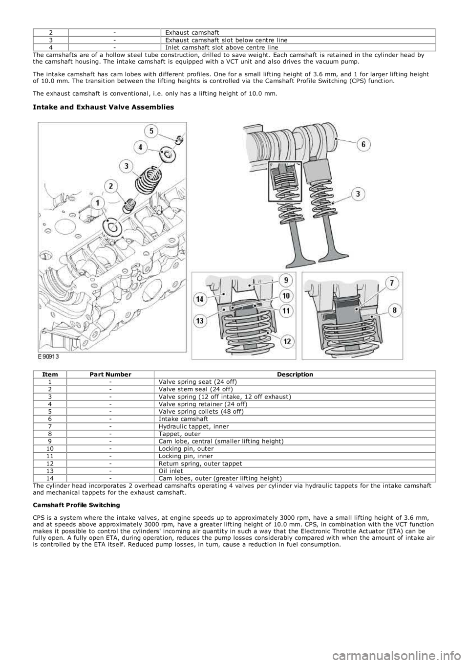
2-Exhaust camshaft3-Exhaust camshaft slot below cent re line4-Inlet camshaft slot above cent re lineThe cams hafts are of a hollow st eel t ube cons t ruction, drilled t o s ave weight . Each camshaft is ret ained in t he cylinder head bythe cams haft hous ing. The int ake cams haft is equipped wit h a VCT unit and also drives the vacuum pump.
The intake camshaft has cam lobes wit h different profiles. One for a small lift ing height of 3.6 mm, and 1 for larger lift ing heightof 10.0 mm. The t ransit ion bet ween t he lift ing height s is cont rolled via the Cams haft Profile Swit ching (CPS) funct ion.
The exhaus t cams haft is convent ional, i.e. only has a lifting height of 10.0 mm.
Intake and Exhaust Valve Assemblies
ItemPart NumberDescription1-Valve s pring s eat (24 off)2-Valve s t em s eal (24 off)3-Valve s pring (12 off int ake, 12 off exhaus t )4-Valve s pring ret ainer (24 off)5-Valve s pring collets (48 off)6-Intake camshaft7-Hydraulic t appet , inner8-Tappet , outer9-Cam lobe, central (s maller lift ing height)10-Locking pin, out er11-Locking pin, inner12-Ret urn s pring, outer tappet13-O il inlet14-Cam lobes , outer (great er lift ing height )The cylinder head incorporat es 2 overhead camshaft s operating 4 valves per cylinder via hydraulic t appet s for the intake camshaftand mechanical t appets for the exhaust cams haft .
Camshaft Profile Sw itching
CPS is a sys tem where t he int ake valves , at engine s peeds up to approximat ely 3000 rpm, have a s mall lifting height of 3.6 mm,and at s peeds above approximat ely 3000 rpm, have a great er lift ing height of 10.0 mm. CPS, in combinat ion wit h t he VCT funct ionmakes it poss ible to cont rol t he cylinders' incoming air quant it y in s uch a way that t he Electronic Throt t le Act uat or (ETA) can befully open. A fully open ETA, during operat ion, reduces t he pump los s es cons iderably compared wit h when the amount of int ake airis controlled by t he ETA its elf. Reduced pump los s es , in turn, cause a reduction in fuel consumpt ion.
Page 622 of 3229
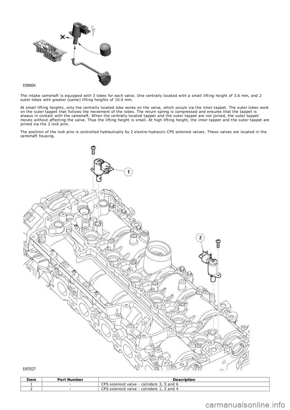
The intake camshaft is equipped wit h 3 lobes for each valve. One cent rally locat ed wit h a small lift ing height of 3.6 mm, and 2out er lobes wit h great er (s ame) lifting height s of 10.0 mm.
At small lift ing height s, only t he cent rally locat ed lobe works on t he valve, which occurs via t he inner t appet . The out er lobes workon the outer t appet t hat follows t he movement of t he lobes. The ret urn spring is compres s ed and ens ures that t he tappet isalways in cont act wit h t he camshaft . W hen the cent rally locat ed t appet and t he out er t appet are not joined, t he outer tappetmoves without affect ing the valve. Thus the lifting height is s mall. At high lift ing height, t he inner t appet and t he out er t appet arejoined via t he 2 lock pins .
The pos it ion of the lock pins is cont rolled hydraulically by 2 elect ro-hydraulic CPS solenoid valves . Thes e valves are locat ed in t hecams haft hous ing.
ItemPart NumberDescription1-CPS s olenoid valve - cylinders 3, 5 and 62-CPS s olenoid valve - cylinders 1, 2 and 4
Page 623 of 3229
One s olenoid cont rols t he valves for cylinders 1, 2 and 4 whils t t he other cont rols t he valves for cylinders 3, 5 and 6. The solenoidstherefore cont rol 6 valves each (when t he engine has 2 int ake valves and 2 exhaus t valves per cylinder).
The pos it ion of the s olenoids valves , on or off, are cont rolled by t he ECMFor addit ional information, refer t o: Elect ronic Engine Cont rols (303-14A Elect ronic Engine Controls - I6 3.2L Pet rol, Des cript ion andOperation)..
The inner t appet works like a hydraulic t appet , which compens at es for any wear. The valve clearance is t herefore '0'.
The exhaus t cams haft is convent ional and has a lift ing height of 10.0 mm. The t appets are mechanical (i.e. have valve clearance).
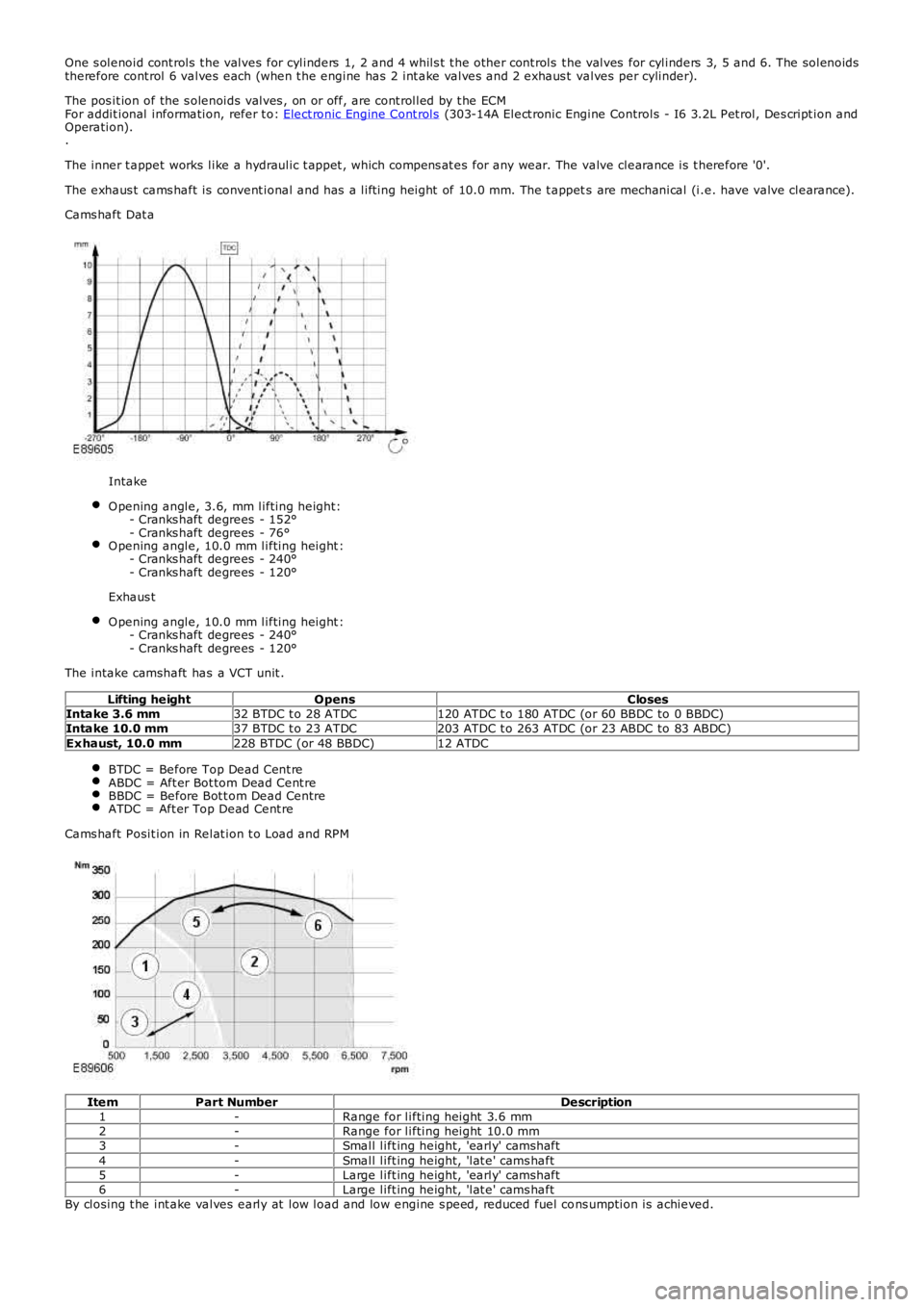
Cams haft Dat a
Intake
O pening angle, 3.6, mm lifting height:- Cranks haft degrees - 152°- Cranks haft degrees - 76°O pening angle, 10.0 mm lifting height :- Cranks haft degrees - 240°- Cranks haft degrees - 120°
Exhaus t
O pening angle, 10.0 mm lifting height :- Cranks haft degrees - 240°- Cranks haft degrees - 120°
The intake camshaft has a VCT unit .
Lifting heightOpensClosesIntake 3.6 mm32 BTDC t o 28 ATDC120 ATDC t o 180 ATDC (or 60 BBDC to 0 BBDC)Intake 10.0 mm37 BTDC t o 23 ATDC203 ATDC t o 263 ATDC (or 23 ABDC to 83 ABDC)Exhaust, 10.0 mm228 BTDC (or 48 BBDC)12 ATDC
BTDC = Before Top Dead Cent reABDC = Aft er Bot tom Dead Cent reBBDC = Before Bot t om Dead CentreATDC = Aft er Top Dead Cent re
Cams haft Posit ion in Relat ion t o Load and RPM
ItemPart NumberDescription1-Range for lifting height 3.6 mm2-Range for lifting height 10.0 mm3-Small lift ing height, 'early' camshaft4-Small lift ing height, 'lat e' cams haft5-Large lift ing height, 'early' camshaft6-Large lift ing height, 'lat e' cams haftBy closing t he int ake valves early at low load and low engine s peed, reduced fuel cons umption is achieved.
Page 624 of 3229
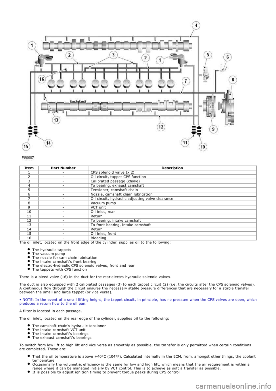
ItemPart NumberDescription1-CPS s olenoid valve (x 2)2-Oil circuit , t appet CPS funct ion3-Calibrated pass age (choke)4-To bearing, exhaus t cams haft5-Tensioner, cams haft chain6-Noz zle, cams haft chain lubricat ion7-Oil circuit , hydraulic adjus ting valve clearance8-Vacuum pump9-VCT unit10-Oil inlet , rear11-Ret urn12-To bearing, int ake cams haft13-To front bearing, intake camshaft14-Ret urn15-Oil inlet , front16-BleedingThe oil inlet , locat ed on the front edge of t he cylinder, s upplies oil t o t he following:
The hydraulic t appet sThe vacuum pumpThe noz zle for cam chain lubricat ionThe int ake cams haft 's front bearingThe electro-hydraulic CPS s olenoid valves , front and rearThe t appet s with CPS funct ion
There is a bleed valve (16) in t he duct for t he rear elect ro-hydraulic s olenoid valves .
The duct is als o equipped wit h 2 calibrat ed pas sages (3) t o each tappet circuit (2) (i.e. the circuits aft er t he CPS s olenoid valves ).A cont inuous flow through t he circuit ens ures t he neces s ary s t able pres sure differences that are neces s ary for a st able trans ferbet ween the s mall and large t appet (or vice vers a).
• NOTE: In t he event of a s mall lifting height , the t appet circuit , in principle, has no pres s ure when the CPS valves are open, whichproduces a ret urn flow t o t he oil pan.
A filt er is locat ed in each pass age.
The oil inlet , locat ed on the rear edge of t he cylinder, s upplies oil t o the following:
The camshaft chain's hydraulic t ens ionerThe int ake cams haft VCT unitThe int ake cams haft 's bearingsThe exhaus t cams haft's bearings
To switch from low lift t o high lift and vice vers a as s moot hly as pos sible, t he trans fer is only permitt ed when cert ain condit ionsare complet ed. Thes e are:
That the oil t emperature is above +40°C (104°F). Calculat ed int ernally in the ECM, from, amongst ot her t hings , t he coolantt emperatureO ccasionally t he volumetric efficiency is t he s ame for low and high lift , which means t hat the air requirement is wit hin arange where it can be managed init ially by VCT cont rol. This is t o achieve as soft a trans fer as pos sible.It is pos sible t o adjust ignition t iming t o prevent t orque peaks during CPS cont rol