2006 LAND ROVER FRELANDER 2 wheel
[x] Cancel search: wheelPage 10 of 3229
Publi s hed: 11-May-2011
General Information - How To Use This Manual
Des cript ion and Operat ion
Copyright Statement
Copyright.© Land Rover Ltd., 2006
All rights res erved. No part of thi s publ icati on may be reproduced, s tored in a ret ri eval s yst em or t rans mit t ed in any form,electroni c, mechanical, photocopyi ng, recordi ng or other means, wi thout pri or wri tt en permi s si on of Land Rover Ltd.,Banbury Road, Li ght horne, W arwi ck, CV35 0RG
How To Use This Manual
This manual covers al l aspects necess ary in order to s ervi ce the vehicle effect ively.
The manual i s s truct ured into fi ve main secti ons , General Informat ion, Chass is , Powert rai n, El ect ri cal and Body and Paintwit h each s ect ion deali ng wit h a specific part of a vehi cl e s ys t em.
Each of t he five mai n s ect ions contain sub-sect ions deal ing wi th it ems which form a part of t hat s pecific s ys tem.
Pages at t he s t art of the manual li s t all s ect ions avai lable. Each s ect ion has a content s li s t det ail ing, where appli cable,Speci ficat ions, Des cri pt ion and Operati on, Di agnos is and Tes ti ng, General Procedures and Repair Procedures.
W here components need t o be removed or dis ass embled in s equence, each operat ion i n the s equence wil l be identi fi ednumeri cal ly and als o graphi cal ly i n an accompanying i ll us t rat ion.
All l eft -hand and ri ght-hand references t o t he vehi cl e are taken from a posi ti on s itti ng in the driver seat l ooking forward.
All l eft -hand and ri ght-hand references t o t he engi ne are taken from a pos i ti on at the flywheel looki ng t owards t he frontcamshaft pul ley.
Ins pect ion and Verificati on
Vis ual Ins pect ion Chart s , Sympt om Charts and ot her informati on charts (s uch as diagnos t ic rout ines ) or s upplement t estprocedures wit h t echnical s pecificati ons wil l navigat e t he user t o a s peci fi c t es t procedure.
Symptom Chart
The s ymptom chart indicates s ymptoms, s ources and act ions t o addres s a condit ion.
Pinpoint Test s
For el ect ri cal s yst ems , pinpoint t es t s t eps are us ed to identi fy t he s ource of a concern in a logi cal, s t ep-by-s t ep manner.Pinpoint t es t s have two col umns: CONDITIO NS and DETAILS/RESULTS/ACTIONS.
The CONDITIONS column is us ed excl usi vel y for graphi cs and icons (wi th or wi thout capt ions ) and the DETAILS/RESULTS/ACTIONS column provi des direct ion t o another tes t s tep or s pecifi c correct ive acti ons .
The boxed numbers indicate the order in whi ch the des cribed acti on is to be carri ed out.
Component Tes ts
A component t es t is us ed when a component i s t est ed in mult ipl e pinpoint t es t s, or if a procedure i s too compl icated t o beformatt ed wi thi n a s ingle page of t he pinpoint t est .
Graphics
Test graphi cs show the meas urement or t es t t o be carried out i n a t est st ep.
A repres ent ati ve tes t er graphi c is us ed for vol tmet ers and ohmmet ers .
If mult iple measurement s are made i n a s ingle graphic, the t es t leads are drawn wi th a s ol id line unt il t he t es t l ead spl it st o indicate the mult iple measurement s , at which point dashed l ines are used.
Breakout box t ype t es t ers are repres ented by a doubl e circl e t est pi n. Tes t pins are labell ed wit h t he pin number.
• NOTE: Dimens i ons quot ed are t o des ign engineeri ng s pecificati ons wit h s ervice l imits quot ed, where appl icable.
Workshop Manual Organization
The fi ve main s ect ions, t ogether wit h t he areas whi ch they cover are given below:
Section 1 - General Informat ion.Section 2 - Chas si s.Section 3 - Powert rai n.Section 4 - Elect rical.Section 5 - Body and Paint .
Sub-s ect ion numbers appear aft er the i nit ial s ect ion number, for exampl e, Section 412-01 covers Cli mate Cont rol, whi ch ispart of t he electrical s ecti on.
In the number given above, t he first di git of the number ' 4' indicates t he s ect ion i.e. Electrical.
The s econd and t hird digit s ' 12' of t he number indicate the vehicle sys tem i.e. Climate Control.
Page 14 of 3229
Publi s hed: 11-May-2011
General Information - Standard Workshop Practices
Des cript ion and Operat ion
Vehicle in Workshop
W hen working on a vehicl e in the workshop al ways make sure t hat :
W here practi cable, t he parking brake is appli ed and t he wheel s are securely chocked to prevent t he vehi cl e movingforwards or backwards .W henever pos si ble, t he ignit ion key i s removed before any work is carried out on t he vehi cle.If the engine i s t o be run, t here i s adequat e vent il ati on, or an extract ion hos e i s us ed to remove exhaus t fumes.There i s adequat e room to rais e the vehicle and remove t he wheel s , if neces s ary.Fender covers are al ways ins tal led i f any work i s to be carri ed out in t he engine compart ment.W here practi cable, t he batt ery i s dis connected if worki ng on the engi ne, underneath t he vehicle, or if t he vehi cl e i srai sed.
• CAUTIO NS:
Prior to dis connect ing the bat tery, refer to the El ect ri cal Secti on of this manual - Bat tery dis connect ion/connect ion.For addit ional informat ion, refer t o: Specificati ons (414-01 Bat t ery, Mount ing and Cables , Speci ficat ions).
W hen el ect ri c arc wel ding on a vehi cl e, al ways dis connect t he generator wi ri ng to prevent t he pos si bili ty of a s urgeof current caus i ng damage to the i nternal component s of the generat or.
If us i ng welding equipment on t he vehicle, a s uit abl e fire exti nguis her is readily avail able.
Battery - General
• CAUTIO NS:
Prior to carrying out any procedures which i nvol ve dis connect ing/ or connecti ng the bat tery, refer t o t he ElectricalSect ion of t his manual - Batt ery di sconnect ion/connect ion.For addit ional informat ion, refer t o: Specificati ons (414-01 Bat t ery, Mount ing and Cables , Speci ficat ions).
A di s charged bat tery condit ion may have been caus ed by an electrical short ci rcuit . If t his condit ion exis t s there wil lbe an apparentl y li ve circuit on the vehicle even when al l normal circuit s are s wit ched off. This can cause arcing when t hejumper cables are connect ed.
W hi le it i s not recommended that the vehicl e is jump s t art ed, i t is recognized t hat thi s may occas ionall y be t he onl ypracti cal way t o mobi lize a vehi cl e. Prior t o at tempt ing a jump s t art , reference must be made to the El ect ri cal Secti on oft hi s manual - Jump St art ing.
Followi ng jump s tart ing of a dis abl ed vehi cle, the di s charged bat tery mus t be checked for s erviceabili ty and recharged offt he vehi cl e as s oon as poss ibl e t o avoi d permanent damage.
Do not rel y on t he generator t o res t ore a di s charged bat tery. For a generat or t o recharge a batt ery, it woul d take i n exces sof eight hours cont inuous dri vi ng wi th no addi ti onal loads placed on t he batt ery.
Always make s ure that t he jumper cabl es are adequate for the tas k.Always make s ure that t he s lave batt ery i s of the same vol tage as t he vehicle bat tery. The bat teries mus t beconnected i n paral lel.Always make s ure that s wit chabl e electric circui ts are s wi tched off before connecti ng jumper cabl es. This reducest he ri sk of arci ng occurring when the final connecti on is made.
Towing the Vehicle
W ARNING: W hen t owing i s neces sary, reference mus t be made to the Jacki ng, Lift ing and Towing Secti on of thi sManual .
W hen t he vehicle i s being t owed dock the remote cont rol and s wit ch on the ignit ion. (s t eering l ock releas ed and warni ngli ght s i ll uminated). Onl y t hen wil l the s t eering, turn s ignal lamps , horn and s t op lamps be operat ional. Fail ure t o followt hes e i nst ructi ons may res ult in pers onal injury. It mus t be noted that wit h t he engine not running, t he power s t eering andbrake boost er wil l be inoperat ive t herefore, great er effort wil l be needed t o s t eer t he vehicle and apply the brakes .
General Installation Instructions
Component removal
W henever pos si ble, clean component s and the surroundi ng area before removal .
Blank off openings expos ed by component removal .Followi ng dis connecti on, s eal fuel, oil or hydrauli c li nes i mmediat ely us ing sui table bl anki ng plugs or caps .Seal open ends of expos ed oil ways us i ng sui table tapered hardwood pl ugs or cons pi cuous pl as t ic pl ugs .Immediat el y a component i s removed, place it i n a sui table contai ner; us e a s eparate cont ai ner for each componentand it s as s ociat ed part s .
Page 17 of 3229
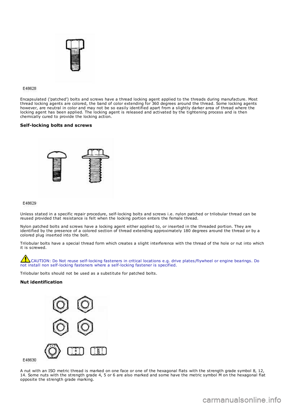
Encaps ulated ('pat ched') bolt s and s crews have a t hread l ocking agent appl ied t o t he t hreads during manufact ure. Mos tt hread locking agent s are col ored, the band of color extending for 360 degrees around the t hread. Some l ocking agentshowever, are neutral in color and may not be s o eas il y identi fi ed apart from a s li ght ly darker area of thread where t helocking agent has been appli ed. The l ocking agent is releas ed and acti vat ed by t he ti ght ening proces s and is thenchemical ly cured to provide t he locking acti on.
Self-locking bolts and screws
Unles s s tat ed in a s peci fic repair procedure, sel f-locki ng bolt s and s crews i.e. nylon patched or tril obul ar t hread can bereus ed provided t hat res is t ance i s fel t when the locki ng port ion enters t he femal e thread.
Nylon pat ched bolt s and s crews have a l ocking agent eit her appli ed t o, or i ns erted in t he threaded porti on. They areidenti fi ed by t he pres ence of a colored s ect ion of t hread extending approximat ely 180 degrees around the t hread or by acol ored pl ug ins ert ed int o t he bol t.
Tri lobular bolt s have a s pecial t hread form which creates a s light i nt erference wit h t he t hread of the hol e or nut i nto whichit i s s crewed.
CAUTION: Do Not reuse sel f-locki ng fas t eners in crit ical locat ions e.g. drive pl at es/flywheel or engine beari ngs . Donot ins tal l non s elf-locki ng fas teners where a sel f-locki ng fas t ener i s s pecified.
Tri lobular bolt s s hould not be used as a s ubs t it ut e for pat ched bol ts .
Nut identification
A nut wi th an ISO metric t hread i s marked on one face or one of the hexagonal fl ats wit h t he st rengt h grade s ymbol 8, 12,14. Some nuts wi th the st rength grade 4, 5 or 6 are als o marked and s ome have the metric s ymbol M on t he hexagonal fl atoppos it e t he s trengt h grade marking.
Page 24 of 3229
shows signs of fraying.Alw ays disconnect the vehicle battery before carrying out any electric welding on a vehicle installed with anSRS system.
CAUTION: Do not expos e ai rbag modules or s eat belt pre-tens ioners t o t emperat ures exceeding 85° C (185° F).
It should be not ed t hat thes e precaut ions are not res trict ed to operat ions performed when s ervicing t he SRS s yst em. Thes ame care s hould be exerci sed when working on ancil lary sys t ems and components located i n the vi ci nit y of SRScomponents ; t hese include but are not l imi ted t o:
Steering wheel ai rbag, rot ary coupler.Pass enger front airbag.Side curt ain ai rbag modules - front and rear.Seat bel t pre-t ensi oners .SRS harnes ses , li nk leads and connectors.Side (t horax) ai r bags .
Making t he s ys t em s afe
Before working on or in t he vicini ty of SRS component s , make s ure t he s ys t em i s rendered safe by performi ng the foll owingoperati ons :
Remove the remot e cont rol .Dis connect batt ery, eart h lead first .W ai t 2 mi nut es for t he SRS power ci rcuit t o di scharge before commenci ng work.
• NOTE: The SRS us es energy res erve capaci tors to keep t he s yst em act ive i n t he event of electrical supply fail ure undercras h condi ti ons . It is necess ary to al low the capaci tors s uffi ci ent ti me t o dis charge (2 mi nut es ) in order t o avoid t he ris kof accidental deployment.
Ins t allat ion
In order to make s ure s ys tem int egrit y, it is ess enti al t hat the SRS sys tem is regularl y checked and mai nt ained s o t hat itis ready for effecti ve operat ion in t he event of a col lis i on. Carefully ins pect SRS component s before ins tal lati on. Do notins t al l a part t hat shows s i gns of being dropped or i mproperl y handl ed, s uch as dents , cracks or deformat ion.
W ARNING: The integrit y of the SRS sys tems is crit ical for safety reasons . Make s ure t he fol lowing precaut ions arealways adhered t o:
Do not install accessories or other objects to trim panels w hich cover airbags.Never install used SRS components from another vehicle or attempt to repair an SRS component.When repairing an SRS system, only use genuine new parts.Never apply electrical power to an SRS component unless instructed to do so as part of an approved testprocedure.Special fixings are necessary for installing an airbag module – do not use other fixings.Alw ays use new fixings w hen replacing an SRS component and make sure that all fixings are tightened to thecorrect torque.
• CAUTIO NS:
Take care not t o t rap airbag modules when i nst all ing i nt eri or trim components .
Make s ure SRS components are not cont aminat ed by oil or greas e.
• NOTE: Followi ng s eat bel t pre-t ensi oner deployment, t he s eat bel ts can s t ill be used as convent ional seat belt s but wil lneed to be replaced as s oon as poss i bl e t o make s ure full SRS protecti on. Do not us e t he s eat bel ts if t he ret racti onmechani sm i s not working correct ly.
• NOTE: If the SRS component s are to be repl aced, the part number/bar code of the new uni t mus t be recorded.
SRS component t es t ing precauti ons
The SRS component s are t riggered us ing relati vel y l ow operati ng current s, al ways adhere to the foll owing :
W ARNING: Never us e a mul ti meter or ot her general purpose equi pment on SRS components. Us e only Land Roverapproved diagnos t ic equipment t o diagnos e sys tem faul ts .
Page 27 of 3229
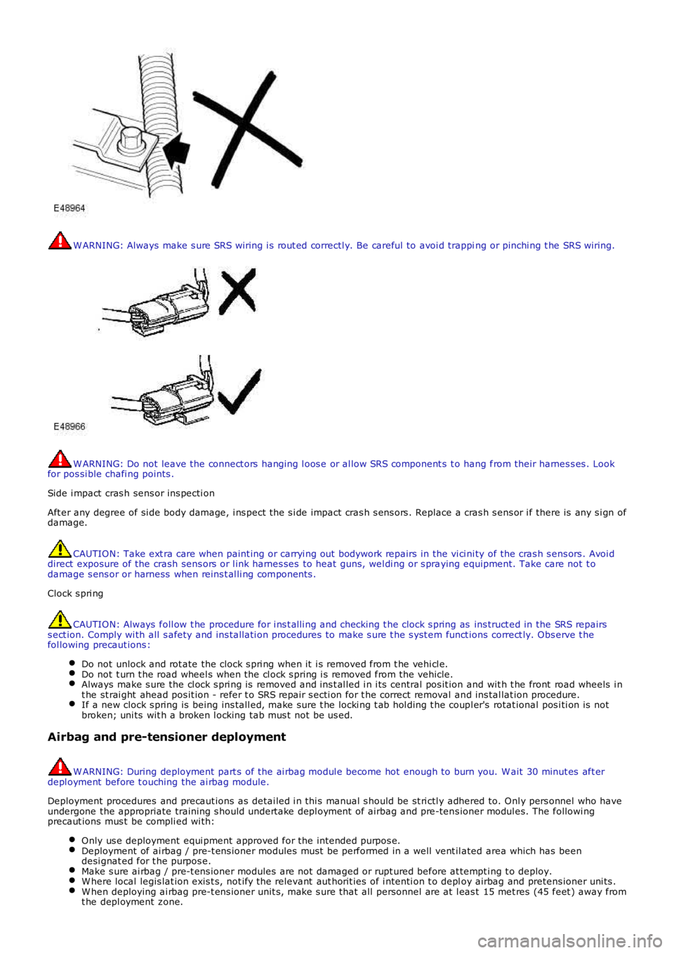
W ARNING: Always make s ure SRS wiring i s rout ed correctl y. Be careful to avoi d trapping or pinchi ng t he SRS wiring.
W ARNING: Do not leave the connect ors hanging l oos e or al low SRS component s t o hang from their harnes s es . Lookfor pos si ble chafi ng points .
Side i mpact cras h sens or ins pecti on
Aft er any degree of si de body damage, i ns pect the s i de impact cras h s ens ors . Replace a cras h s ens or i f there is any s i gn ofdamage.
CAUTION: Take ext ra care when paint ing or carryi ng out bodywork repairs in the vi ci ni ty of the cras h s ens ors . Avoi ddirect exposure of the crash sens ors or l ink harnes ses to heat guns, wel di ng or s praying equipment. Take care not t odamage s ens or or harness when reins t al li ng components .
Clock s pri ng
CAUTION: Always foll ow t he procedure for i ns t alli ng and checking t he clock s pring as ins truct ed in the SRS repairss ect ion. Comply wi th all s afety and ins tal lati on procedures to make s ure t he s yst em funct ions correct ly. Obs erve t hefol lowing precaut ions :
Do not unlock and rot ate the clock s pri ng when it i s removed from t he vehi cl e.Do not t urn t he road wheel s when the cl ock s pring i s removed from the vehicle.Always make s ure the cl ock s pri ng is removed and ins t al led i n i ts central pos it ion and wit h t he front road wheels i nt he st rai ght ahead pos it ion - refer t o SRS repair s ecti on for t he correct removal and ins tal lat ion procedure.If a new clock s pring is being ins tall ed, make sure t he locki ng t ab hol ding t he coupl er's rotat ional pos i ti on is notbroken; uni ts wit h a broken l ocking tab mus t not be us ed.
Airbag and pre-tensioner deployment
W ARNING: During deployment part s of the ai rbag modul e become hot enough to burn you. W ait 30 minut es aft erdepl oyment before t ouching the ai rbag module.
Deployment procedures and precaut ions as detai led i n thi s manual s hould be st ri ctl y adhered to. Onl y pers onnel who haveundergone the appropriate training s hould undert ake depl oyment of airbag and pre-tens ioner modul es. The followi ngprecaut ions mus t be compli ed wi th:
Only us e deployment equi pment approved for the intended purpos e.Deployment of ai rbag / pre-t ens ioner modules mus t be performed in a well vent il ated area which has beendesi gnat ed for t he purpos e.Make s ure ai rbag / pre-t ens ioner modules are not damaged or rupt ured before at tempt ing t o deploy.W here local legis lat ion exis t s, not ify the relevant aut horit ies of i ntenti on t o deploy airbag and pretens ioner uni ts .W hen deploying ai rbag pre-t ens ioner unit s, make s ure that all personnel are at l eas t 15 met res (45 feet ) away fromt he depl oyment zone.
Page 28 of 3229
Make s ure deployment tool is connect ed correct ly, in compl iance wit h t he ins truct ions det ai led i n t he SRS s ect ion oft hi s manual. In part icular, make sure depl oyment t ool is NOT connect ed t o batt ery s upply before connecti ng t oairbag modul e connector.W hen deploying s eat belt pre-tens ioners , make s ure pre-t ensi oner unit i s s ecured correctl y t o t he s eat .W hen removing deployed airbag modul es and pre-tens ioner uni ts , wear protecti ve clothi ng. Us e gl oves and s ealdepl oyed uni ts in a pl ast ic bag.Followi ng depl oyment of any component of t he SRS s ys t em wi thi n the vehicl e, al l SRS components mus t berepl aced. DO NOT reus e or s al vage any parts of t he SRS s yst em.Do not lean over an airbag module when connect ing deployment equi pment .
If a vehi cl e i s to be s crapped, undepl oyed ai rbag modules and pre-t ens ioner unit s mus t be manually depl oyed. In thi s cas eairbags can be deployed i n the vehicl e. Before deployment, make s ure the ai rbag modul e is secure wit hi n i ts correctmounti ng posi ti on. Deployment of the driver's airbag in the vehicle may damage the st eering wheel ; if t he vehi cl e i s notbeing s crapped, deploy t he module out s ide of t he vehi cl e.
SRS Component Replacement Policy
• CAUTIO NS:
T he restraints control module (RCM) must be replaced after every time any SRS component has beendeployed.
The SRS s ide impact sens or mus t be replaced if t here are any s igns of phys i cal damage or if t he RCM i s regi st eri ng afaul t.
The fol lowing informati on detail s t he policy for replacement of SRS component s as a res ult of a vehicle accident.
Impacts w hich do not deploy the airbags or pre-tensioners
Check for s truct ural damage in t he area of the i mpact paying parti cular at tent ion t o bumper armat ures , longi tudi nal s andbracket ry.
Impacts w hich deploy the airbags or pre-tensioners
The repl acement and ins pect ion poli cy is dependent on t he t ype and severi ty of t he cras h condi ti on. The foll owingguideli nes are t he mi ni mum that s houl d be exercis ed as a res ul t of the deployment of s pecific SRS component s .
Check for structural damage in the area of impact paying particular attention to bumper armatures, longitudinalsand bracketry.
Front Airbag Deployment - Driver and Passenger
CAUTION: If the front airbags are deployed, the followi ng components mus t be replaced:
Dri ver ai rbag moduleSteering wheelPass enger ai rbag moduleIns t rument panelFly l eads (where appl icabl e) connect ing front ai rbag modules t o SRS harnes sAll s eat bel t buckle pre-t ensi onerAll occupied seat s at the ti me of t he crash s hould have their s eat bel ts replacedAny s eat bel t wit h a deployed ret ract or pretens ioner s hould be replaced.Rotary couplerAny front impact s ens ors that have been phys ically damaged or i f a faul t is being regis teredRCM
Additionally, the following items must be inspected for damage and replaced as necessary:
Front pass enger's seat belt retract or and webbi ng, t ongue l atching funct ion, 'D' loop and body anchorage poi ntRear seat belt buckl es, webbing, buckle covers , body anchorage point s and t ongue l atching funct ionFront s eat frames and head res trai ntsSteering column - if adjus tment i s los t or if t here are s igns of col laps eSeat bel t hei ght adjust ersRear seat belt s
Side Ai r Bags
CAUTION: If the s i de (t horax) air bags are deployed, the foll owi ng component s mus t be replaced on t he s ide of t hevehi cl e on whi ch the deployment occurred:
Side (t horax) ai rbagAny s ide i mpact s ens ors t hat have been phys i cal ly damaged or if a fault i s being regi st eredRCM
Additionally, the following items must be inspected for damage and replaced as necessary:
Front s eat bel ts , ret ractors and webbing, tongue lat chi ng functi on, 'D' l oop and body anchorage point sRear seat belt buckl es, webbing, buckle covers , t ongue l atching funct ion, and body anchorage point sFront s eat frame and head res traint sDoor trim cas i ngSeat bel t hei ght adjust ers
Page 31 of 3229
Invert the compres s or and gravi ty drain the oi l into a calibrated meas uri ng cyl inder. Rotat e t he compres sor clut ch tomake s ure the compres s or is complet el y drai ned.Note the quanti ty of oi l drained (Y cm³).Calculate the quanti ty of oi l to be drained from t he new compres sor us ing t he fol lowi ng formula:X cm³ — (Y cm³ +20 cm³) = Q cm³Remove the drain pl ug from the new compres s or and drain Q cm3 of oi l. ins t al l and tight en t he compres sor drai nplug.
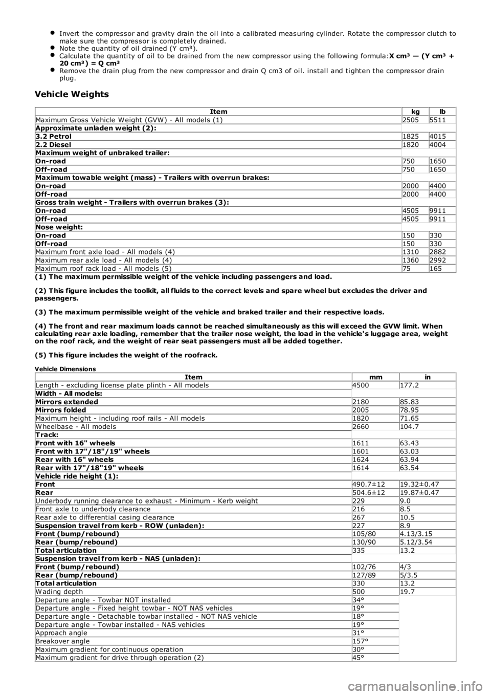
Vehicle Weights
Itemkglb
Maximum Gros s Vehicle W eight (GVW ) - Al l model s (1)25055511Approximate unladen w eight (2):
3.2 Petrol18254015
2.2 Diesel18204004Maximum weight of unbraked trailer:
On-road7501650
Off-road7501650Maximum towable weight (mass) - T railers with overrun brakes:
On-road20004400
Off-road20004400Gross train weight - T railers with overrun brakes (3):
On-road45059911
Off-road45059911Nose w eight:
On-road150330
Off-road150330Maximum front axl e l oad - All models (4)13102882
Maximum rear axle load - All models (4)13602992
Maximum roof rack l oad - All models (5)75165(1) T he maximum permissible weight of the vehicle including passengers and load.
(2) T his figure includes the toolkit, all fluids to the correct levels and spare w heel but excludes the driver andpassengers.
(3) T he maximum permissible weight of the vehicle and braked trailer and their respective loads.
(4) T he front and rear maximum loads cannot be reached simultaneously as this will exceed the GVW limit. Whencalculating rear axle loading, remember that the trailer nose w eight, the load in the vehicle' s luggage area, w eighton the roof rack, and the weight of rear seat passengers must all be added together.
(5) T his figure includes the weight of the roofrack.
Vehicle Dimensions
ItemmminLengt h - excluding l icens e pl ate pl int h - All models4500177.2
Width - All models:
Mirrors extended218085.83Mirrors folded200578.95
Maximum height - including roof rail s - Al l model s182071.65
W heelbas e - Al l model s2660104.7T rack:
Front w ith 16" wheels161163.43
Front w ith 17"/18"/19" wheels160163.03Rear with 16" wheels162463.94
Rear with 17"/18"19" wheels161463.54
Vehicle ride height (1):Front490.7±1219.32±0.47
Rear504.6±1219.87±0.47
Underbody running cl earance t o exhaus t - Mi nimum - Kerb wei ght2299.0Front axle t o underbody clearance2168.5
Rear axl e t o different ial cas i ng cl earance26710.5
Suspension travel from kerb - ROW (unladen):2278.9Front (bump/rebound)105/804.13/3.15
Rear (bump/rebound)130/905.12/3.54
T otal articulation33513.2Suspension travel from kerb - NAS (unladen):
Front (bump/rebound)102/764/3
Rear (bump/rebound)127/895/3.5T otal articulation33013.2
W adi ng dept h50019.7
Depart ure angle - Towbar NOT ins tall ed34°Depart ure angle - Fi xed hei ght towbar - NOT NAS vehicles19°
Depart ure angle - Detachabl e towbar ins t al led - NOT NAS vehicle18°
Depart ure angle - Towbar i ns t alled - NAS vehi cl es19°Approach angl e31°
Breakover angle157°
Maximum gradient for conti nuous operat ion30°Maximum gradient for drive t hrough operat ion (2)45°
Page 32 of 3229

(1) Ride height is measured vertically from wheel center to underside of wheelarch. All figures are with vehicle at'Show room' height - full fluids, full tank of fuel, no occupants/luggage, tires inflated to normal pressures.
(2) 5 seconds maximum duration.