2006 LAND ROVER FRELANDER 2 oil change
[x] Cancel search: oil changePage 15 of 3229
Clean bench and provide marking mat eri al s , labels and containers before di s as s embli ng components .
Disassembling
Obs erve s crupul ous cl eanl ines s when dis as sembl ing component s, parti cul arly when brake, fuel, air s us pens ion or hydrauli cs ys t em parts are dis as sembl ed. A part icle of dirt or cloth fragment could caus e a s eri ous malfunct ion i f trapped i n t hes es ys t ems .
Blow out al l tapped holes , crevi ces , oil ways and flui d pass ages wit h dry, compres s ed air.
W ARNING: Sui table eye protecti on mus t be worn.
Us e s uit abl e marker i nk to identi fy mat ing parts , do not us e a s cri ber or cent re punch as t hey coul d ini ti at e cracksor dis torti on.W i re or t ape mat ing part s t oget her where neces s ary t o prevent acci dent al i nterchange.Suit abl y identi fy parts which are to be renewed and t o thos e part s requi ri ng further ins pect ion. Keep thes e part ss eparate.To make s ure that t he correct replacement part has been obt ained, do not dis card a part due for renewal unt il aftercomparing i t wit h t he new part.
Cleaning Components
Always us e cleaning agents whi ch are s uit able for the work being undert aken and the component s being cleaned. NEVERus e gasol ine (pet rol ) as a cleaning agent (degreas er). Always make s ure that the component bei ng cleaned is compati blewit h t he cleaning agent.
Always follow the manufact urer's i ns t ructi ons regarding the us e of cleaning agents and make sure t hat t he envi ronment inwhich t he work is being undert aken is s uit able. See Healt h and Safet y Precaut ions for furt her informati on regardi ngcleaning.
General Inspection of Components
All component s s houl d be i ns pect ed for wear or damage before reas s embl ing.
Always make s ure that component t o be i ns pected i s clean and free from oil or greas e.W hen a component is t o be checked di mensi onal ly agains t desi gn s pecified values , use the appropriat e meas uringequi pment i.e. micromet ers , verniers, s urface plates , dial t es t i ndi cat ors (DTI).Always make s ure that all meas uri ng equi pment is correct ly cali brat ed before us e.Reject a component which i s not wit hin specified values /l imi ts or i f it appears t o be damaged.A component may be rei ns t alled if dimens ions obt ai ned during checki ng are at t he maximum t olerance l imi t and itis in an undamaged condi ti on.Bearing journal clearances should be checked where neces s ary us ing Pl ast igauge.
Joints and Joint Faces
All gas ket s s houl d be i ns t alled dry unles s s tat ed otherwis e. Always appl y t he s pecified l ubricant to O-rings and i nst allO-ri ngs us ing the fingers onl y.
Us e gasket removal s pray and/or plas t ic s crapers t o remove traces of old gas ket.
CAUTION: DO NOT us e met al s crapers or emery clot h as t hes e may damage the s eali ng s urfaces.
Many joi nts us e s ealants ins tead of gasket s as t he seal ing medium. W here t his is t he cas e, t he s eal ant t oget her wit h i tspart number wil l be found l is ted i n t he rel evant repair operat ion and al so in the s ealants table.
CAUTION: Always remove all t races of the ol d s eal ant prior t o reas s embly. Use plas tic s crapers, s pecifi ed s olvent swhere avail abl e or dry, l int free clot h. DO NOT us e met al scrapers or emery clot h as t hese may damage the seali ngs urfaces . Make sure t hat s eali ng s urfaces are free from oi l or greas e as sealant s wil l not adhere properly to contaminateds urfaces .
Do not all ow s ealant to ent er tapped holes or oil ways .
Locking Devices
Always repl ace locki ng devi ces wit h one of the s ame des ign and of t he correct s ize.
Tab washers
Always release locki ng t abs before l oos ening fixings , do not reus e t ab washers.
Locknuts
Always us e a backing s panner when l oos ening and t ighteni ng locknut s, brake and fuel pipe unions .
Roll pins
Always i ns t all new roll pins of t he correct s ize.
Circlips
Always i ns t all new circl ips ens uri ng that t hey are of t he correct s ize for t he groove.
Page 35 of 3229
Any s praying s houl d preferably be carri ed out in venti lat ed boot hs which i ncorporat e faci li ti es for removi ng vapors ands pray dropl et s from the breathing zone.
W ear appropri at e gl oves , eye and res pirat ory protecti on.
Antifreeze
May be flammabl e when undilut ed.
Vapors may be gi ven off from coolant anti freeze when heat ed. Avoid breathi ng thes e vapors .
Anti freeze may be absorbed through t he s kin i n t oxi c or harmful quanti ti es. Ant ifreeze, i f s wal lowed, can be fat al; SEEKIMMEDIAT E MEDICAL AT T ENT ION.
Battery Acids
See als o Al kal is and Acids .
Gas es releas ed duri ng bat t ery charging are expl osi ve. Al ways remove t he batt ery from t he vehi cl e pri or to chargi ng. Neverus e naked flames or al low s parks near charging or recentl y charged bat t eries . NEVER add aci d t o a bat tery, t he chemicalreacti on produced wil l be vi olent and expl os i ve. In cases of eye contact, was h affected area wit h copious amount s of wat erand SEEK IMMEDIAT E MEDICAL AT T ENT ION.
Make s ure t here i s adequat e vent il ati on during bat tery charging, obs erve NO SMOKING POLICY .
Brake Pads and Linings
Always fit t he correct grade and s peci fi cat ion of brake pads and l inings . W hen renewi ng pads and lini ngs , always repl aceas complete axl e s ets .
Brake and Clutch Fluid
Splas hes to t he s kin and eyes are irri tat ing and i n t he long t erm can be damagi ng, avoid prolonged s ki n cont act. In casesof eye cont act , wash affect ed area wi th copious amount s of water and SEEK IMMEDIATE MEDICAL ATTENTION.
Chemical Materials
All chemical materials should al ways be used wit h caut ion and st ored and handled wi th care. They may be toxic, harmful,corros ive, irri tant or highly fl ammable and gi ve ri se to hazardous fumes and dus t s.
The effect s of exces s ive expos ure to chemi cal s may be i mmediat e or delayed; briefl y experienced or permanent ;cumulati ve; s uperficial; life t hreatening; or may reduce l ife expect ancy.
Chemical Materials - Do's
Do careful ly read and observe hazard and precaut ion warnings given on material cont ai ners (labels ) and in anyaccompanyi ng leaflets , pos ters or ot her ins truct ions . Material heal th and safet y data s heet s can be obtained frommanufacturers .Do remove chemi cal mat eri al s from the s kin and cl othing as soon as pract icable after s oil ing. Change heavily soi ledclothi ng and have it cleaned.Do organi se work pract ices and prot ect ive clot hing t o avoi d s oil ing of t he s ki n and eyes .Do avoid breat hing vapors , aeros ols , dus t s or fumes ; inadequat e container labell ing; fi re and expl os i on hazards .Do was h before job breaks, before eati ng, s moking, dri nki ng or usi ng t oi let faci lit ies when handli ng chemicalmat erial s.Do keep work areas clean, unclut tered and free of s pi ll s.Do s t ore chemical materials according to nat ional and local regul at ions .Do keep chemical materi als out of t he reach of chi ldren.
Chemical Materials - Do Not
Do Not mi x chemical materials except under the manufact urers ins truct ions ; s ome chemicals can form ot her toxic orharmful chemi cal s, gi ve off t oxi c or harmful fumes or become explos ive when mixed t oget her.Do Not s pray chemical materials , part icularly t hose bas ed on s olvents , i n confined spaces , for example when peopleare ins ide a vehicle.Do Not apply heat or fl ame t o chemical materi als except under the manufact urers ins truct ions . Some are hi ghlyfl ammable and some may rel ease toxic or harmful fumes .Do Not l eave contai ners open. Fumes given off can bui ld up to t oxic, harmful or explos ive concentrati ons . Somefumes are heavier than ai r and wil l accumulate in confi ned areas s uch as pi ts .Do Not t rans fer chemical materi als t o unlabell ed cont ainers .Do Not clean hands or cl othing wit h chemicals . Chemical s , parti cul arly sol vent s and fuel s, wi ll dry ski n and maycaus e i rrit ati on leading t o dermat it is or be abs orbed t hrough t he s ki n i n t oxi c or harmful quanti ti es .Do Not us e empt ied containers for ot her mat eri al s except when t hey have been cleaned under s upervis edcondi ti ons .Do Not s niff or smel l chemi cal mat eri al s , even brief expos ure to hi gh concentrat ions of fumes can be toxic orharmful.
Corrosion Protection Materials
Some corrosi on prot ect ion mat eri als are highly flammabl e – obs erve NO SMOKING POLICY.
Thes e materials are vari ed and the manufact urers ins truct ions mus t always be foll owed. The mat eri als may contai ns olvent s , res ins or petroleum product s. Skin and eye cont act s houl d be avoided. They s hould only be s prayed in condit ionsof adequate vent il at ion and not i n confined s paces .
Page 119 of 3229
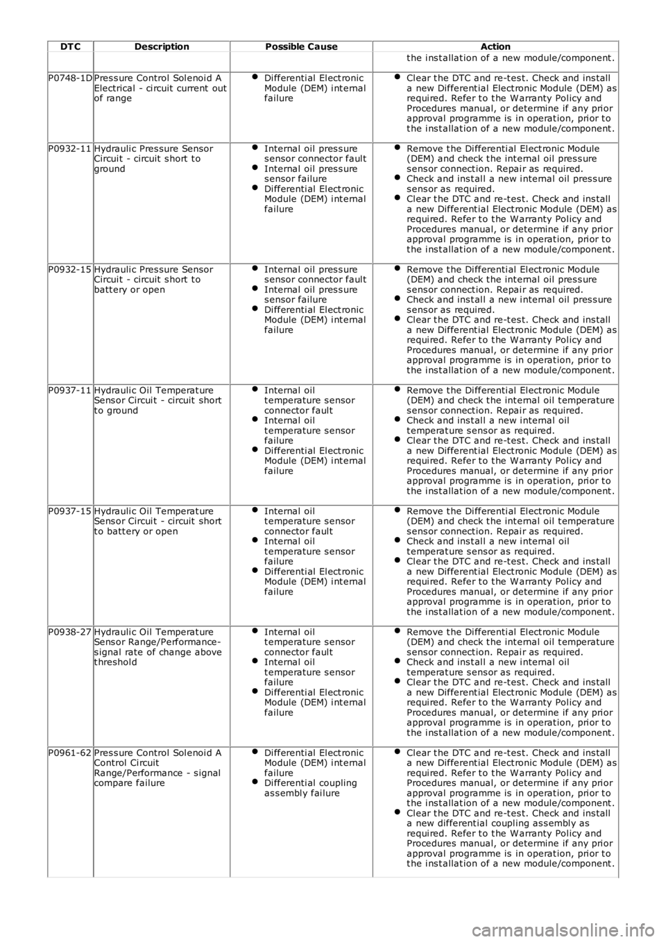
DT CDescriptionPossible CauseAction
t he i ns t allat ion of a new module/component .
P0748-1DPres s ure Control Sol enoi d AElectrical - ci rcuit current outof range
Di fferenti al El ect ronicModule (DEM) i nt ernalfailure
Cl ear t he DTC and re-t es t. Check and ins talla new Different ial Elect ronic Module (DEM) asrequi red. Refer t o t he W arranty Pol icy andProcedures manual, or determine if any pri orapproval programme is in operat ion, pri or t ot he i ns t allat ion of a new module/component .
P0932-11Hydrauli c Pres sure SensorCircui t - circuit s hort t oground
Internal oil pres s ures ensor connector faul tInternal oil pres s ures ensor failureDi fferenti al El ect ronicModule (DEM) i nt ernalfailure
Remove t he Di fferenti al El ect ronic Module(DEM) and check t he int ernal oil pres s ures ens or connect ion. Repai r as required.Check and ins t al l a new i nternal oil pres s ures ens or as required.Cl ear t he DTC and re-t es t. Check and ins talla new Different ial Elect ronic Module (DEM) asrequi red. Refer t o t he W arranty Pol icy andProcedures manual, or determine if any pri orapproval programme is in operat ion, pri or t ot he i ns t allat ion of a new module/component .
P0932-15Hydrauli c Pres sure SensorCircui t - circuit s hort t obatt ery or open
Internal oil pres s ures ensor connector faul tInternal oil pres s ures ensor failureDi fferenti al El ect ronicModule (DEM) i nt ernalfailure
Remove t he Di fferenti al El ect ronic Module(DEM) and check t he int ernal oil pres s ures ens or connect ion. Repai r as required.Check and ins t al l a new i nternal oil pres s ures ens or as required.Cl ear t he DTC and re-t es t. Check and ins talla new Different ial Elect ronic Module (DEM) asrequi red. Refer t o t he W arranty Pol icy andProcedures manual, or determine if any pri orapproval programme is in operat ion, pri or t ot he i ns t allat ion of a new module/component .
P0937-11Hydrauli c Oil Temperat ureSens or Circui t - circuit shortt o ground
Internal oilt emperature s ensorconnector faul tInternal oilt emperature s ensorfailureDi fferenti al El ect ronicModule (DEM) i nt ernalfailure
Remove t he Di fferenti al El ect ronic Module(DEM) and check t he int ernal oil t emperatures ens or connect ion. Repai r as required.Check and ins t al l a new i nternal oilt emperat ure s ens or as requi red.Cl ear t he DTC and re-t es t. Check and ins talla new Different ial Elect ronic Module (DEM) asrequi red. Refer t o t he W arranty Pol icy andProcedures manual, or determine if any pri orapproval programme is in operat ion, pri or t ot he i ns t allat ion of a new module/component .
P0937-15Hydrauli c Oil Temperat ureSens or Circui t - circuit shortt o batt ery or open
Internal oilt emperature s ensorconnector faul tInternal oilt emperature s ensorfailureDi fferenti al El ect ronicModule (DEM) i nt ernalfailure
Remove t he Di fferenti al El ect ronic Module(DEM) and check t he int ernal oil t emperatures ens or connect ion. Repai r as required.Check and ins t al l a new i nternal oilt emperat ure s ens or as requi red.Cl ear t he DTC and re-t es t. Check and ins talla new Different ial Elect ronic Module (DEM) asrequi red. Refer t o t he W arranty Pol icy andProcedures manual, or determine if any pri orapproval programme is in operat ion, pri or t ot he i ns t allat ion of a new module/component .
P0938-27Hydrauli c Oil Temperat ureSens or Range/Performance-s ignal rate of change abovet hreshol d
Internal oilt emperature s ensorconnector faul tInternal oilt emperature s ensorfailureDi fferenti al El ect ronicModule (DEM) i nt ernalfailure
Remove t he Di fferenti al El ect ronic Module(DEM) and check t he int ernal oil t emperatures ens or connect ion. Repai r as required.Check and ins t al l a new i nternal oilt emperat ure s ens or as requi red.Cl ear t he DTC and re-t es t. Check and ins talla new Different ial Elect ronic Module (DEM) asrequi red. Refer t o t he W arranty Pol icy andProcedures manual, or determine if any pri orapproval programme is in operat ion, pri or t ot he i ns t allat ion of a new module/component .
P0961-62Pres s ure Control Sol enoi d AControl Ci rcuitRange/Performance - s ignalcompare failure
Di fferenti al El ect ronicModule (DEM) i nt ernalfailureDi fferenti al couplingas s embl y fai lure
Cl ear t he DTC and re-t es t. Check and ins talla new Different ial Elect ronic Module (DEM) asrequi red. Refer t o t he W arranty Pol icy andProcedures manual, or determine if any pri orapproval programme is in operat ion, pri or t ot he i ns t allat ion of a new module/component .Cl ear t he DTC and re-t es t. Check and ins talla new different ial coupl ing as s embl y asrequi red. Refer t o t he W arranty Pol icy andProcedures manual, or determine if any pri orapproval programme is in operat ion, pri or t ot he i ns t allat ion of a new module/component .
Page 190 of 3229
Ensure that the steering wheel is in the straight ahead position, do not turn the st eering w heel prior to checking the
fluid level.
Check t hat the flui d level is t o t he mi d-way mark between the MAX and MIN marks on t he fluid res ervoir, t op-up i f
neces s ary. Clean t he area around the res ervoi r fi ll er cap, remove cap.
CAUTION:
Do not fill reservoir above the MAX mark.
If necess ary, t op-up us ing t he recommended fluid to the mid-way mark on the reservoi r.
For addit ional informat ion, refer t o: Specificati ons (211-02 Power St eering, Specificati ons).
Ins t all the res ervoir fill er cap.
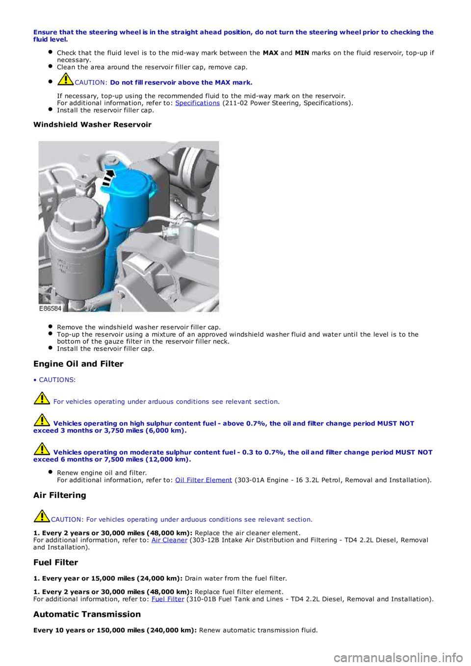
Windshield Washer Reservoir
Remove the winds hi eld was her res ervoir fill er cap.
Top-up t he res ervoir us ing a mi xt ure of an approved wi nds hiel d was her flui d and wate
r unti l the level i s t o the
bott om of t he gauze fil ter i n t he res ervoir fil ler neck. Ins t all the res ervoir fill er cap.
Engine Oil and Filter
• CAUTIO NS: For vehi cl es operati ng under arduous condi ti ons see relevant secti on.
Vehicles operating on high sulphur content fuel - above 0.7%, the oil and filter cha nge period MUST NOT
exceed 3 months or 3,750 miles (6,000 km).
Vehicles operating on moderate sulphur content fuel - 0.3 to 0.7%, the oil and filte r change period MUST NOT
exceed 6 months or 7,500 miles (12,000 km).
Renew engi ne oil and fil ter.
For addit ional informat ion, refer t o: Oil Fil ter El ement (303-01A Engine - I6 3.2L Pet rol , Removal and Ins t allat ion).
Air Filtering
CAUTION: For vehi cl es operati ng under arduous condi ti ons s ee relevant s ecti on.
1. Every 2 years or 30,000 miles (48,000 km): Replace the ai r cl eaner element .
For addit ional informat ion, refer t o: Air Cl eaner (303-12B Int ake Ai r Dis t ri but ion and Fi lt ering - TD4 2.2L Di es el, Removal
and Ins t allat ion).
Fuel Filter
1. Every year or 15,000 miles (24,000 km): Drai n water from the fuel fi lt er.
1. Every 2 years or 30,000 miles (48,000 km): Replace fuel fi lt er el ement.
For addit ional informat ion, refer t o: Fuel Fil ter (310-01B Fuel Tank and Lines - TD4 2.2L Dies el, Removal and Ins tall ati on).
Automatic Transmission
Every 10 years or 150,000 miles (240,000 km): Renew automat ic t rans mis s ion flui d.
Page 192 of 3229
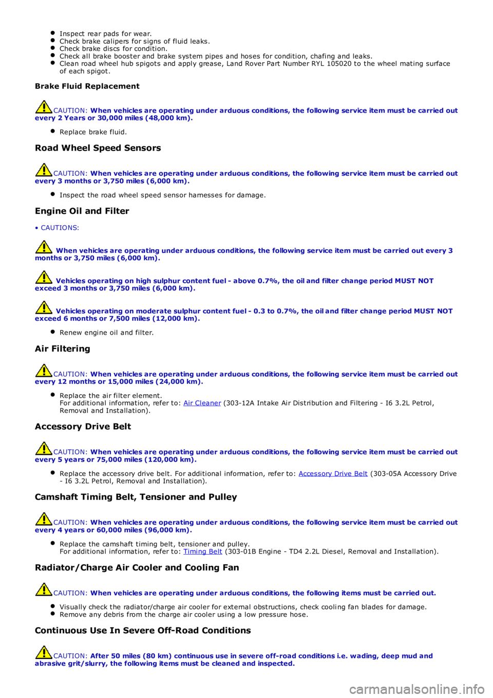
Ins pect rear pads for wear.
Check brake cal ipers for s igns of fl ui d l eaks .
Check brake dis cs for condi ti on.
Check al l brake boos t er and brake s ys t em pipes and hos es for condi ti on, chafi ng and
leaks.Clean road wheel hub s pigot s and appl y greas e, Land Rover Part Number RY L 105020 t o
t he wheel mat ing surface
of each s pigot . Brake Fluid Replacement
CAUTION:
When vehicles are operating under arduous conditions, the following service item mus t be carried out
every 2 Years or 30,000 miles (48,000 km).
Replace brake fluid. Road Wheel Speed Sensors
CAUTION:
When vehicles are operating under arduous conditions, the following service item mus t be carried out
every 3 months or 3,750 miles (6,000 km).
Ins pect the road wheel s peed s ens or harness es for damage. Engine Oil and Filter
• CAUTIO NS:
When vehicles are operating under arduous conditions, the following service item mus t be carried out every 3
months or 3,750 miles (6,000 km).
Vehicles operating on high sulphur content fuel - above 0.7%, the oil and filter cha nge period MUST NOT
exceed 3 months or 3,750 miles (6,000 km).
Vehicles operating on moderate sulphur content fuel - 0.3 to 0.7%, the oil and filte r change period MUST NOT
exceed 6 months or 7,500 miles (12,000 km).
Renew engi ne oil and fil ter. Air Filtering
CAUTION:
When vehicles are operating under arduous conditions, the following service item mus t be carried out
every 12 months or 15,000 miles (24,000 km).
Replace the ai r fi lt er el ement.
For addit ional informat ion, refer t o: Air Cl eaner (303-12A Int ake Ai r Dis t ri but ion and Fi lt ering - I6 3.2L Petrol ,
Removal and Inst all ati on). Accessory Drive Belt
CAUTION:
When vehicles are operating under arduous conditions, the following service item mus t be carried out
every 5 years or 75,000 miles (120,000 km).
Replace the access ory drive bel t. For addi ti onal informat ion, refer to: Acces s ory Drive Belt (303-05A Acces s ory Drive
- I6 3.2L Pet rol, Removal and Ins tal lat ion). Camshaft Timing Belt, Tensioner and Pulley
CAUTION:
When vehicles are operating under arduous conditions, the following service item mus t be carried out
every 4 years or 60,000 miles (96,000 km).
Replace the cams haft t iming belt , tens ioner and pul ley.
For addit ional informat ion, refer t o: Timi ng Belt (303-01B Engi ne - TD4 2.2L Dies el, Removal and Inst all ati on).
Radiator/Charge Air Cooler and Cooling Fan
CAUTION:
When vehicles are operating under arduous conditions, the following items must be ca rried out.
Vis uall y check t he radiat or/charge air cool er for ext ernal obst ruct ions, check cooli ng fan bl ades for damage.Remove any debris from t he charge air cool er us i ng a l ow pres s ure hos e.
Continuous Use In Severe Off-Road Conditions
CAUTION:
After 50 miles (80 km) continuous use in severe off-road conditions i.e. w ading, dee p mud and
abrasive grit/slurry, the following items must be cleaned and inspected.
Page 319 of 3229
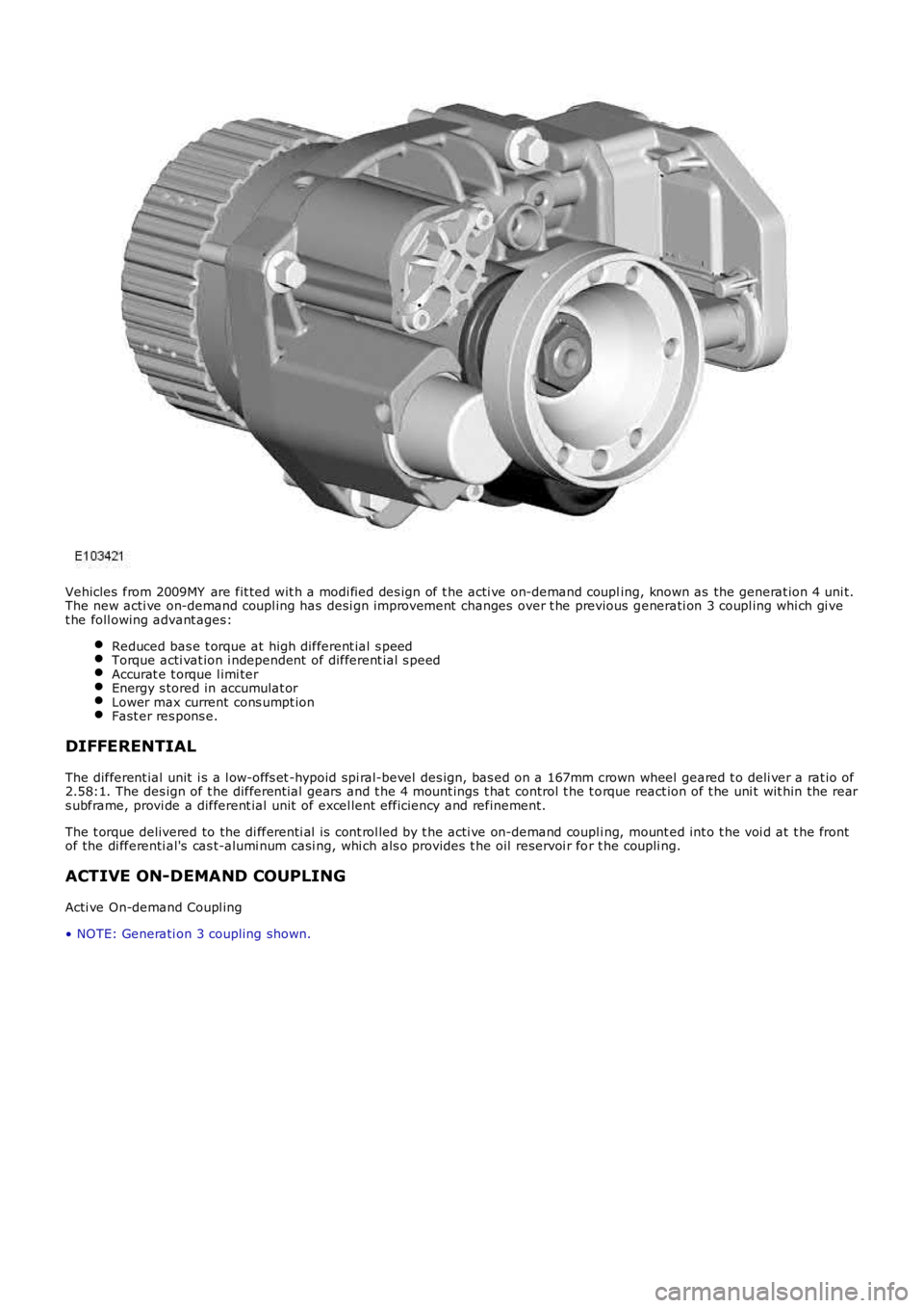
Vehicles from 2009MY are fit ted wit h a modi fied des ign of t he acti ve on-demand coupling, known as the generat ion 4 uni t.The new acti ve on-demand coupl ing has desi gn improvement changes over t he previous generati on 3 coupl ing whi ch gi vet he foll owing advant ages:
Reduced bas e t orque at high different ial s peedTorque acti vat ion i ndependent of different ial s peedAccurat e t orque l imi terEnergy s tored in accumulat orLower max current cons umpt ionFast er res pons e.
DIFFERENTIAL
The different ial unit i s a l ow-offs et -hypoid spi ral-bevel des ign, bas ed on a 167mm crown wheel geared t o deli ver a rat io of2.58:1. The des ign of t he different ial gears and t he 4 mount ings t hat control t he t orque react ion of t he uni t wit hin the rears ubframe, provi de a different ial unit of excel lent efficiency and refinement.
The t orque delivered to the di fferenti al i s cont rol led by t he acti ve on-demand coupli ng, mount ed int o t he voi d at t he frontof the di fferenti al's cas t-alumi num casi ng, whi ch als o provi des t he oil reservoi r for t he coupli ng.
ACTIVE ON-DEMAND COUPLING
Acti ve On-demand Coupl ing
• NOTE: Generati on 3 coupling shown.
Page 603 of 3229
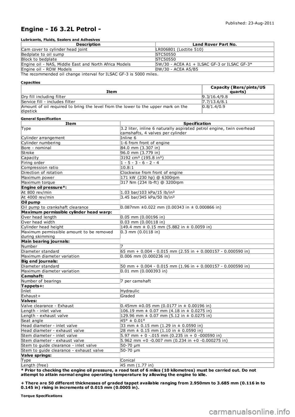
Publi s hed: 23-Aug-2011
Engine - I6 3.2L Petrol -
Lubricants, Fluids, Sealers and AdhesivesDescriptionLand Rover Part No.
Cam cover to cyli nder head jointLR006801 (Loct it e 510)
Bedplate to oi l s umpSTC50550Block t o bedpl ateSTC50550
Engine oil - NAS, Mi ddl e Eas t and Nort h Africa Models5W /30 - ACEA A1 + ILSAC GF-3 or ILSAC GF-3*
Engine oil - ROW Models0W /30 - ACEA A5/B5The recommended oil change i nterval for ILSAC GF-3 is 5000 mi les .
C apacities
ItemCapacity (liters/pints/USquarts)
Dry fi ll i ncludi ng fi lt er9.3/16.4/9.8
Service fil l - includes fi lt er7.7/13.6/8.1Amount of oil required t o bri ng the level from the lower to the upper mark on thedips t ick0.8/1.4/0.9
General Specification
ItemSpecificationType3.2 li ter, inli ne 6 nat urall y aspi rat ed pet rol engine, twi n overheadcams haft s, 4 val ves per cylinderCyli nder arrangementInli ne 6
Cyli nder numberi ng1-6 from front of engine
Bore - nominal84.0 mm (3.307 in)St roke96.0 mm (3.779 in)
Capaci ty3192 cm³ (195.8 i n³)
Firing order1 - 5 - 3 - 6 - 2 - 4Compres s ion rati o10.8:1
Di recti on of rotat ionCl ockwis e from front of engi ne
Maximum power171 kW (230 hp) @ 6300rpmMaximum t orque317 Nm (234 lb-ft ) @ 3200rpm
Engine oil pressure*:
At 800 rev/min1.03 bar/103 kPa/15 lb/in²At 4000 rev/min3.45 bar/345 kPa/50 lb/in²
Oil pump
Oi l pump to cranks haft clearance0.087mm ±0.022 mm (0.00343 i n ± 0.000866 i n)Maximum permissible cylinder head w arp:
Over head length0.05 mm (0.00196 i n)
Over head widt h0.03 mm (0.00118 i n)Cyli nder head height149.4 mm ± 0.15 mm (5.882 in ± 0.0059 i n)
Maximum permi s si ble amount t o be removedduri ng s ki mmi ng0.3 mm (0.0118 in)
Main bearing journals:
Number7
Di amet er s tandard65 mm + 0.004 - 0.015 mm (2.55 in + 0.000157 - 0.000590 in)Maximum diamet er variat ion0.006 mm (0.000236 in)
Big end journals:
Di amet er s tandard50 mm + 0.004 - 0.015 mm (1.96 in + 0.000157 - 0.000590 in)Maximum diamet er variat ion0.01 mm (0.000393 i n)
Camshaft:
Number of bearings7 per cams haftT appets+:
InletHydrauli c
Exhaus t +GradedValves:
Valve clearance - Exhaus t0.45mm ±0.05 mm (0.0177 in ± 0.00196 in)
Lengt h - i nlet valve106.19 mm ± 0.07 mm (4.18 in ± 0.0275 i n)Lengt h - exhaus t valve129.96 mm ± 0.07 mm (5.12 in ± 0.0275 i n)
Seat angl e45° ± 0.01°
Head diamet er - inlet valve33 mm ± 0.15 mm (1.29 in ± 0.0590 i n)Head diamet er - exhaus t val ve28 mm ± 0.15 mm (1.10 in ± 0.0590 i n)
St em diamet er - inlet valve5.97 mm + 0 -.015 mm (0.235 in + 0 -000590 i n)
St em diamet er - exhaus t val ve5.962 mm +0 -0.007 mm (0.234 in +0 -0.000275 i n)St em t o guide clearance - i nlet val ve50-70 µm
St em t o guide clearance - exhaus t valve50-70 µm
Valve springs:TypeConical
Lengt h (free)45 mm (1.77 in)
* Prior to checking the engine oil pressure, a road test of 6 miles (10 kilometres) must be carried out. Do notattempt to attain normal engine operating temperature by allowing the engine to idle.
+ T here are 50 different thicknesses of graded tappet available ranging from 2.950mm to 3.685 mm (0.116 in to0.145 in) rising in increments of 0.015 mm (0.0005 in).
Torque Specifications
Page 625 of 3229
For addit ional information, refer t o: Elect ronic Engine Cont rols (303-14A Elect ronic Engine Controls - I6 3.2L Pet rol, Des cript ion andOperation).
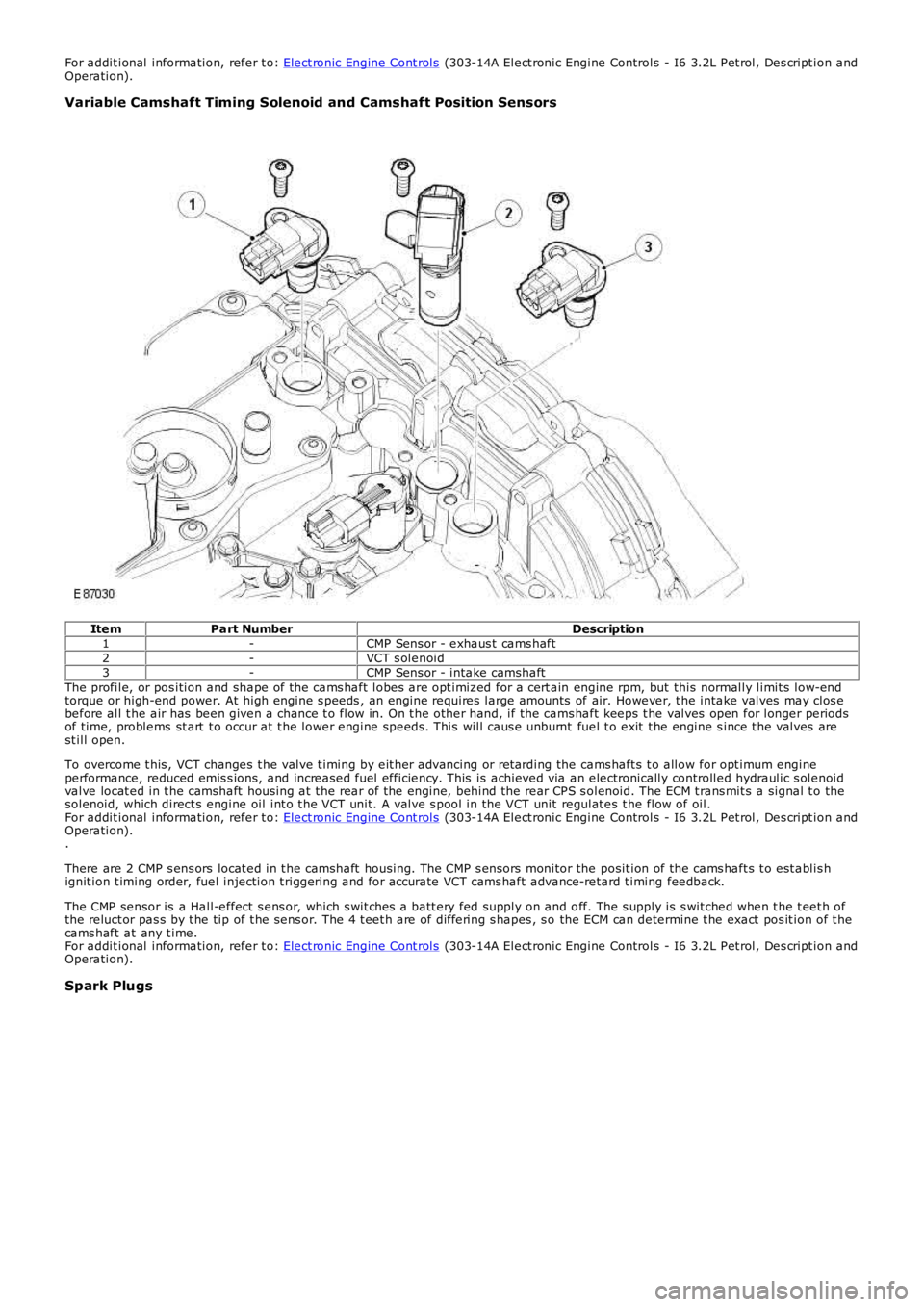
Variable Camshaft Timing Solenoid and Camshaft Position Sensors
ItemPart NumberDescription1-CMP Sens or - exhaus t cams haft2-VCT s olenoid3-CMP Sens or - intake camshaftThe profile, or pos ition and shape of the cams haft lobes are opt imiz ed for a cert ain engine rpm, but this normally limit s low-endtorque or high-end power. At high engine s peeds , an engine requires large amounts of air. However, t he intake valves may clos ebefore all t he air has been given a chance t o flow in. On t he other hand, if the cams haft keeps t he valves open for longer periodsof time, problems st art t o occur at t he lower engine speeds . This will caus e unburnt fuel t o exit t he engine s ince t he valves arest ill open.
To overcome t his , VCT changes t he valve t iming by eit her advancing or ret arding the cams haft s t o allow for opt imum engineperformance, reduced emis s ions, and increased fuel efficiency. This is achieved via an electronically controlled hydraulic s olenoidvalve locat ed in t he camshaft housing at t he rear of t he engine, behind the rear CPS s olenoid. The ECM t rans mit s a signal t o thesolenoid, which direct s engine oil int o t he VCT unit. A valve s pool in the VCT unit regulat es t he flow of oil.For addit ional information, refer t o: Elect ronic Engine Cont rols (303-14A Elect ronic Engine Controls - I6 3.2L Pet rol, Des cript ion andOperation)..
There are 2 CMP s ens ors locat ed in t he camshaft housing. The CMP s ensors monitor the posit ion of the cams haft s t o est ablis hignit ion t iming order, fuel injection t riggering and for accurate VCT cams haft advance-retard t iming feedback.
The CMP sensor is a Hall-effect s ens or, which s wit ches a batt ery fed supply on and off. The s upply is s wit ched when t he t eet h ofthe reluct or pas s by t he tip of t he sens or. The 4 t eet h are of differing s hapes , s o the ECM can determine t he exact pos it ion of t hecams haft at any t ime.For addit ional information, refer t o: Elect ronic Engine Cont rols (303-14A Elect ronic Engine Controls - I6 3.2L Pet rol, Des cript ion andOperation).
Spark Plugs