2006 LAND ROVER FRELANDER 2 wheel torque
[x] Cancel search: wheel torquePage 24 of 3229
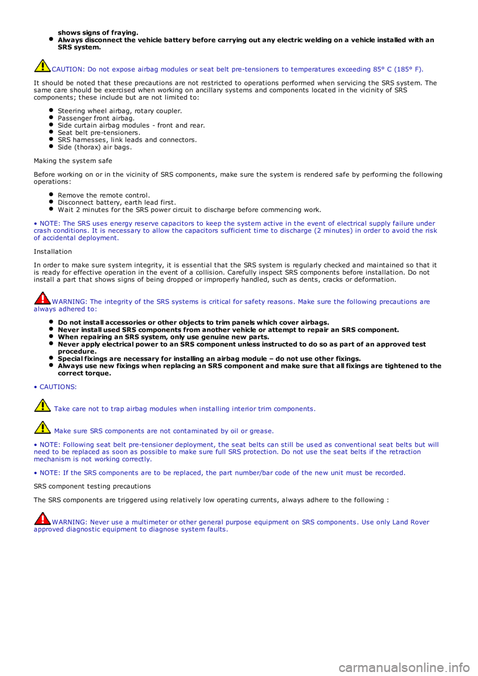
shows signs of fraying.Alw ays disconnect the vehicle battery before carrying out any electric welding on a vehicle installed with anSRS system.
CAUTION: Do not expos e ai rbag modules or s eat belt pre-tens ioners t o t emperat ures exceeding 85° C (185° F).
It should be not ed t hat thes e precaut ions are not res trict ed to operat ions performed when s ervicing t he SRS s yst em. Thes ame care s hould be exerci sed when working on ancil lary sys t ems and components located i n the vi ci nit y of SRScomponents ; t hese include but are not l imi ted t o:
Steering wheel ai rbag, rot ary coupler.Pass enger front airbag.Side curt ain ai rbag modules - front and rear.Seat bel t pre-t ensi oners .SRS harnes ses , li nk leads and connectors.Side (t horax) ai r bags .
Making t he s ys t em s afe
Before working on or in t he vicini ty of SRS component s , make s ure t he s ys t em i s rendered safe by performi ng the foll owingoperati ons :
Remove the remot e cont rol .Dis connect batt ery, eart h lead first .W ai t 2 mi nut es for t he SRS power ci rcuit t o di scharge before commenci ng work.
• NOTE: The SRS us es energy res erve capaci tors to keep t he s yst em act ive i n t he event of electrical supply fail ure undercras h condi ti ons . It is necess ary to al low the capaci tors s uffi ci ent ti me t o dis charge (2 mi nut es ) in order t o avoid t he ris kof accidental deployment.
Ins t allat ion
In order to make s ure s ys tem int egrit y, it is ess enti al t hat the SRS sys tem is regularl y checked and mai nt ained s o t hat itis ready for effecti ve operat ion in t he event of a col lis i on. Carefully ins pect SRS component s before ins tal lati on. Do notins t al l a part t hat shows s i gns of being dropped or i mproperl y handl ed, s uch as dents , cracks or deformat ion.
W ARNING: The integrit y of the SRS sys tems is crit ical for safety reasons . Make s ure t he fol lowing precaut ions arealways adhered t o:
Do not install accessories or other objects to trim panels w hich cover airbags.Never install used SRS components from another vehicle or attempt to repair an SRS component.When repairing an SRS system, only use genuine new parts.Never apply electrical power to an SRS component unless instructed to do so as part of an approved testprocedure.Special fixings are necessary for installing an airbag module – do not use other fixings.Alw ays use new fixings w hen replacing an SRS component and make sure that all fixings are tightened to thecorrect torque.
• CAUTIO NS:
Take care not t o t rap airbag modules when i nst all ing i nt eri or trim components .
Make s ure SRS components are not cont aminat ed by oil or greas e.
• NOTE: Followi ng s eat bel t pre-t ensi oner deployment, t he s eat bel ts can s t ill be used as convent ional seat belt s but wil lneed to be replaced as s oon as poss i bl e t o make s ure full SRS protecti on. Do not us e t he s eat bel ts if t he ret racti onmechani sm i s not working correct ly.
• NOTE: If the SRS component s are to be repl aced, the part number/bar code of the new uni t mus t be recorded.
SRS component t es t ing precauti ons
The SRS component s are t riggered us ing relati vel y l ow operati ng current s, al ways adhere to the foll owing :
W ARNING: Never us e a mul ti meter or ot her general purpose equi pment on SRS components. Us e only Land Roverapproved diagnos t ic equipment t o diagnos e sys tem faul ts .
Page 142 of 3229
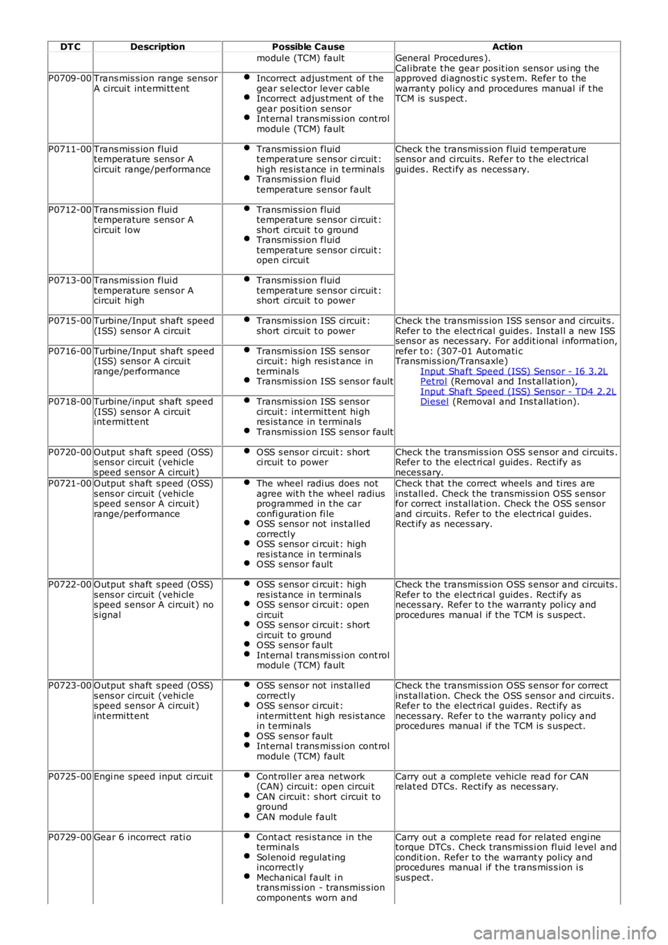
DT C
Description Possible Cause Action
modul e (TCM) fault General Procedures ).
Cal ibrat e t he gear pos it ion sens or us i ng the
approved di agnos ti c s ys t em. Refer to the
warrant y poli cy and procedures manual if t he
TCM is sus pect .
P0709-00
Trans mis s ion range sens or
A circui t int ermi tt ent Incorrect adjus tment of t he
gear s elector lever cabl e Incorrect adjus tment of t he
gear posi ti on s ens or Int ernal t rans mi ss i on cont rol
modul e (TCM) fault P0711-00
Trans mis s ion flui d
temperature s ens or A
circuit range/performance Transmis si on fluid
temperat ure s ens or ci rcuit :
hi gh res is t ance i n t ermi nal s Transmis si on fluid
temperat ure s ens or fault Check t he transmis s ion fluid temperat ure
sens or and ci rcuit s. Refer to t he elect rical
gui des . Recti fy as necess ary.
P0712-00 Trans mis s ion flui d
temperature s ens or A
circuit l ow Transmis si on fluid
temperat ure s ens or ci rcuit :
short ci rcuit t o ground Transmis si on fluid
temperat ure s ens or ci rcuit :
open circui t P0713-00
Trans mis s ion flui d
temperature s ens or A
circuit hi gh Transmis si on fluid
temperat ure s ens or ci rcuit :
short ci rcuit t o power P0715-00
Turbine/Input shaft speed
(ISS) s ens or A circui t Transmis si on ISS ci rcuit :
short ci rcuit t o power Check t he transmis s ion ISS s ens or and circuit s .
Refer to the el ect ri cal guides . Ins tal l a new ISS
sens or as neces sary. For addit ional i nformati on,
refer t o: (307-01 Aut omati c
Transmis s ion/Trans axle)
Input Shaft Speed (ISS) Sensor - I6 3.2L Pet rol (Removal and Ins t al lat ion),
Input Shaft Speed (ISS) Sensor - TD4 2.2L Di esel (Removal and Ins t allat ion).
P0716-00
Turbine/Input shaft speed
(ISS) s ens or A circui t
range/performance Transmis si on ISS s ens or
ci rcuit : high res i st ance in
terminals Transmis si on ISS s ens or fault
P0718-00
Turbine/input shaft speed
(ISS) s ens or A circui t
int ermi tt ent Transmis si on ISS s ens or
ci rcuit : int ermi tt ent hi gh
res is tance in terminals Transmis si on ISS s ens or fault
P0720-00
Output s haft s peed (OSS)
s ens or circuit (vehi cle
s peed s ens or A circuit ) OSS s ens or ci rcuit : s hort
ci rcuit t o power Check t he transmis s ion OSS s ens or and circui ts .
Refer to the el ect ri cal guides . Rect ify as
neces sary.
P0721-00 Output s haft s peed (OSS)
s ens or circuit (vehi cle
s peed s ens or A circuit )
range/performance The wheel radi us does not
agree wit h t he wheel radius
programmed in t he car
confi gurati on fi le OSS s ens or not ins tall ed
correctl y OSS s ens or ci rcuit : high
res is tance in terminals OSS s ens or fault Check t hat t he correct wheels and ti res are
ins tall ed. Check t he transmis si on OSS s ensor
for correct ins t al lat ion. Check t he OSS s ensor
and ci rcuit s. Refer to t he elect rical guides.
Rect ify as neces s ary.
P0722-00 Output s haft s peed (OSS)
s ens or circuit (vehi cle
s peed s ens or A circuit ) no
s ignal OSS s ens or ci rcuit : high
res is tance in terminals OSS s ens or ci rcuit : open
ci rcuit OSS s ens or ci rcuit : s hort
ci rcuit t o ground OSS s ens or fault
Int ernal t rans mi ss i on cont rol
modul e (TCM) fault Check t he transmis s ion OSS s ens or and circui ts .
Refer to the el ect ri cal guides . Rect ify as
neces sary. Refer t o t he warranty pol icy and
procedures manual if t he TCM is s us pect.
P0723-00 Output s haft s peed (OSS)
s ens or circuit (vehi cle
s peed s ens or A circuit )
int ermi tt ent OSS s ens or not ins tall ed
correctl y OSS s ens or ci rcuit :
intermit t ent hi gh res is t ance
in t ermi nals OSS s ens or fault
Int ernal t rans mi ss i on cont rol
modul e (TCM) fault Check t he transmis s ion OSS s ens or for correct
ins tall ati on. Check the OSS s ens or and circuit s .
Refer to the el ect ri cal guides . Rect ify as
neces sary. Refer t o t he warranty pol icy and
procedures manual if t he TCM is s us pect.
P0725-00 Engi ne s peed input ci rcuit Cont roll er area network
(CAN) circui t: open circui t CAN circuit : s hort circui t to
ground CAN module fault Carry out a compl ete vehicle read for CAN
relat ed DTCs. Recti fy as neces sary.
P0729-00 Gear 6 incorrect rati o Cont act resi s tance in the
terminals Sol enoi d regulat ing
incorrectl y Mechanical fault i n
trans mi ss i on - transmis s ion
component s worn and Carry out a compl ete read for related engi ne
torque DTCs . Check trans mi ss i on fl uid l evel and
condit ion. Refer t o the warrant y poli cy and
procedures manual if t he t rans mis s ion i s
sus pect .
Page 272 of 3229
Publi s hed: 11-May-2011
Wheels and Tires -
Wheel Type
• CAUTIO NS:
CAUTIO N: W it h reduced s ize s pare wheel fit ted, do not exceed 50 mph (80 km/h) and repl ace wi th s tandard s izewheel at earlies t opportuni ty.
CAUTIO N: Do not use power t ool s when operat ing t he s pare wheel winch, rais e and l ower winch manual ly us i ng handt ool s only.
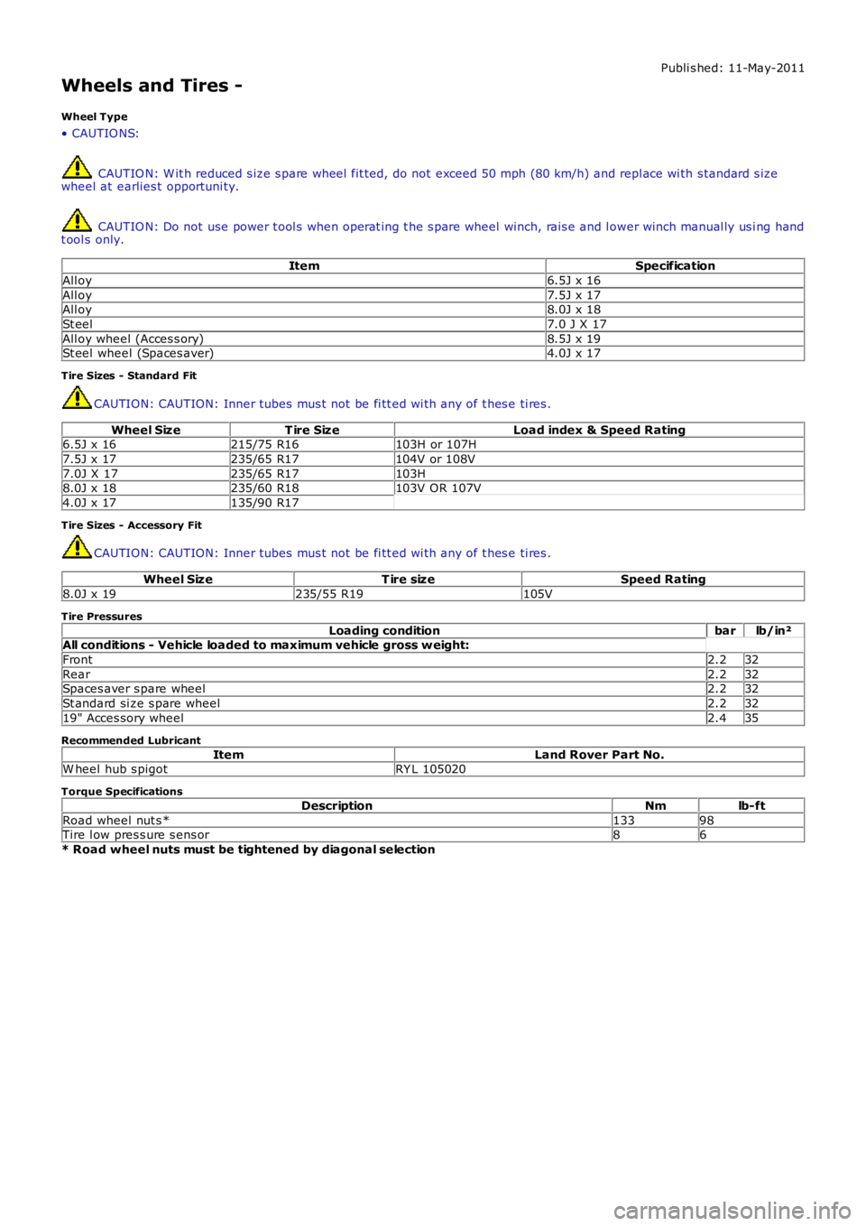
ItemSpecification
All oy6.5J x 16
All oy7.5J x 17All oy8.0J x 18
St eel7.0 J X 17
All oy wheel (Acces s ory)8.5J x 19St eel wheel (Spaces aver)4.0J x 17
Tire Sizes - Standard Fit
CAUTION: CAUTION: Inner tubes mus t not be fi tt ed wi th any of t hes e ti res .
Wheel SizeT ire SizeLoad index & Speed Rating6.5J x 16215/75 R16103H or 107H
7.5J x 17235/65 R17104V or 108V
7.0J X 17235/65 R17103H8.0J x 18235/60 R18103V OR 107V
4.0J x 17135/90 R17
Tire Sizes - Accessory Fit
CAUTION: CAUTION: Inner tubes mus t not be fi tt ed wi th any of t hes e ti res .
Wheel SizeT ire sizeSpeed Rating
8.0J x 19235/55 R19105V
Tire Pressures
Loading conditionbarlb/in²All conditions - Vehicle loaded to maximum vehicle gross w eight:
Front2.232
Rear2.232Spaces aver s pare wheel2.232
St andard si ze s pare wheel2.232
19" Acces sory wheel2.435
Recommended Lubricant
ItemLand Rover Part No.W heel hub s pigotRY L 105020
Torque Specifications
DescriptionNmlb-ft
Road wheel nut s *13398Tire l ow pres s ure s ens or86
* Road wheel nuts must be tightened by diagonal selection
Page 278 of 3229

The care point s detai led i n 'Tire Changing' earlier i n t hi s s ect ion must be foll owed to avoi d damage to the sens or. If a news ens or is fi tt ed, a new nut, s eal and was her mus t als o be fit ted and the s ensor nut t ightened t o t he correct torque asgiven i n the Service Repai r Manual .
Instrument Cluster Indications
ItemPart NumberDescription
1-Low ti re press ure warning indicator
2-Mes s age cent reThe warni ng indicati ons to the driver are common on all vehi cl es fi tt ed wi th TPMS. The dri ver i s alerted t o s ys tem warningsby a l ow t ire pres s ure warning i ndi cat or in t he i ns t rument clus ter and an appli cable text mes s age in t he mes s age cent re.
The TPMS s oft ware wit hi n t he CJB pas s es s yst em s t atus i nformat ion to the i nst rument clus ter on t he medi um s peed CANbus. The i nst rument clus t er t hen convert s t his dat a int o il lumi nat ion of t he warni ng indi cat or and di spl ay of an appropriat emes s age.
W hen t he i gni ti on is s wi tched on, the warning i ndi cat or is i ll uminated for 3 s econds for a bul b check.
• NOTE: If the vehicle is not fit ted wi th the TPMS, t he warning indicator wi ll not ill uminat e.
The ins t rument clus ter checks, wit hi n t he 3 s econd bul b check peri od, for a CAN bus mes s age from t he TPMS. Duri ng thi st ime the TPMS performs int ernal tes ts and CAN bus ini ti al is ati on. The warning i ndi cat or wil l be ext inguis hed if t he TPMSs oft ware does not is s ue a faul t mes s age or t ire pres s ure warning mes s age.
If a TPMS faul t warning mess age is det ect ed by t he ins t rument clus ter at ignit ion on, t he warni ng indicator wi ll flas h for 75s econds aft er the 3 s econd bulb check period and t hen remai n permanent ly i lluminated.
If a ti re pres sure warni ng mes sage i s detected by the i nst rument clus t er at i gni ti on on, the warning i ndi cat or wil lexti nguis h briefly after t he 3 s econd bulb check peri od, before re-il lumi nat ing to indicate a ti re pres sure warni ng.
The fol lowing table shows t he warni ng indicat or funct ionali ty for given event s:
EventInstrument Cluster IndicationsLow pres s ure warning l imit reached in hi ghs peed modeW arni ng indicat or i ll uminated. 'TY RE PRESSURES LO W FOR SPEED' mes sagedis played.Low pres s ure warning l imit reached in onewheel in l ow s peed modeW arni ng indicat or i ll uminated. 'CHECK ALL TY RE PRESSURES XX LOW 'mes sage di spl ayed.
Low pres s ure warning l imit reached in moret han one wheel i n low s peed modeW arni ng indicat or i ll uminated. 'CHECK ALL TY RE PRESSURES' mes s agedis played.
W arning l imi t reached in any 'running' wheeland no l ocat ion s peci fi ed by TPMSW arni ng indicat or i ll uminated. 'CHECK ALL TY RE PRESSURES' mes s agedis played.
W arning l imi t reached in s pare wheel (if fit ted)W arni ng indicat or i ll uminated for 20 s econds and again at s ubsequentignit ion cycles . 'CHECK SPARE TY RE PRESSURE' mess age dis played.
TPMS faul tW arni ng indicat or flas hing for 75 s econds and then remains permanent lyil lumi nat ed. 'TY RE PRESSURE MONITORING SY STEM FAULT' mes sagedis played.
Page 283 of 3229
Publi s hed: 11-May-2011
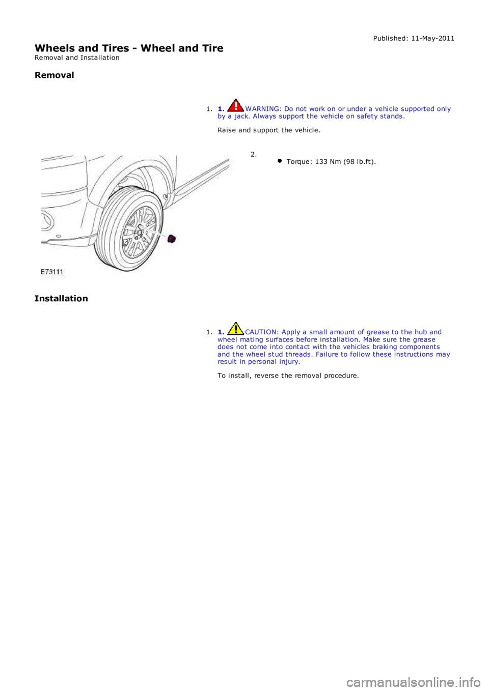
Wheels and Tires - Wheel and Tire
Removal and Inst all ati on
Removal
1. W ARNING: Do not work on or under a vehi cle s upported onl yby a jack. Al ways support t he vehi cl e on s afet y s tands .
Rais e and s upport t he vehi cl e.
1.
Torque: 133 Nm (98 l b.ft).2.
Installation
1. CAUTION: Apply a small amount of greas e t o t he hub andwheel mati ng s urfaces before ins tal lat ion. Make sure t he greas edoes not come int o cont act wi th the vehicles braki ng component sand t he wheel s t ud threads . Failure t o fol low thes e ins t ructi ons mayres ult in pers onal injury.
To i nst all , revers e t he removal procedure.
1.
Page 295 of 3229
Each sub-sys tem operates in di fferent ways in relati on t o t he sel ect ed Terrai n Res pons e program t o achieve t he opt imumt racti on, s t abi lit y and eas e of cont rol for t he t errai n encount ered.
Engine Management System (EMS)
The EMS can change t he accel erator pedal maps to change the amount of t orque per percent age of pedal travel .
Each terrain program uses a combi nat ion of operat ing paramet ers for each sub-sys tem. Changing bet ween terrain programsini ti at es a di fferent s et of operat ing characteris ti cs which wil l be noti ceable to the driver, for example; i f the accel erat orpedal i s held i n a const ant pos i ti on and the terrain program is changed from Gras s /Gravel /Snow t o Sand, the driver wil lnoti ce the t orque and engine s peed increas e. If t he t errai n program is changed from Sand t o Grass /Gravel/Snow, t he dri verwil l not ice a reduct ion in t orque and engine s peed.
• NOTE: The change i n t orque and engine s peed can take approximat ely 30 s econds and care mus t be taken not to confus et he Terrai n Respons e s yst em operat ion wit h an EMS faul t.
Transmission Control (Automatic transmission only)
The t ransmis s ion control modul e changes t he shi ft maps for the Terrain Respons e program s elect ed. Thi s changes t he s hi ftpoints providing early or l at e ups hift s and downs hi ft s .
For example, i n t he Gras s /Gravel /Snow program, the trans mi ss i on wil l perform early ups hi ft s and very late downs hifts toensure t he transmis si on is in t he highes t gear pos si ble. The hil l det ect ion funct ion of t he Trans mis s ion Cont rol module(TCM) will l ock t he t orque converter and hold whi chever gear i s s el ect ed t o t he engine s peed (RPM) li mit i f neces s ary whendescending a s t eep incli ne. This provi des maximum engi ne braking before t he dri ver needs t o appl y t he brakes.
Sport mode i s only avail abl e when t he general program i s s elected. Sport mode i s disabled i n all Terrain Res pons e s peci alprograms. 'CommandShift ™' is avail abl e in any program.
Active On-Demand Coup ling Control
The act ive on-demand coupli ng cont rol module has 2 operati ng s trat egies ; pre-empt ive and react ive.
The pre-empti ve st rat egy anti ci pat es and predict s the locki ng torque val ue required t o mi ni mi ze sl ip and maxi mizes tabil it y. Each Terrain Res pons e program has a different t hres hol d and i nput cri teria for the pre-empt ive s t rategy. Forexampl e, a higher locki ng t orque would be appl ied on s li ppery s urfaces .
The reacti ve s trategy vari es the amount of locking t orque in res pons e t o t he actual s lip level and t he dynamic behavi or oft he vehi cl e. Each Terrain Res pons e program has a different t hres hol d and input for the react ive s trategy. The reacti ves trategy i mproves vehi cl e t racti on and compos ure by eliminati ng any wheel s pin which has occurred aft er the pre-empt ives trategy was appli ed. The l ocking res pons e appli ed is appli cable to the t errain program sel ect ed. For exampl e, verys ens i ti ve on s lippery surfaces to provide maximum t racti on and mi nimi ze surface damage.
The locking t orque calculati ons use various s ignals from other s ub-s yst ems , for example, engi ne torque, accel erator pedalposi ti on, s elect ed gear, st eeri ng angl e, vehicle s peed, lat eral accelerat ion, yaw behavi or.
The DSC funct ion of t he ABS s ys t em can override t he act ive on-demand coupli ng cont rol and reduce any appl ied l ocki ngt orque during DSC act ion.
ABS System Control
The ABS module cont rols several functi ons and adjust s t he operati ng paramet ers of t hes e funct ions t o opti mize thes elect ed Terrain Res pons e program.
Tracti on Control
Tracti on cont rol us es different s li p/accel erati on thresholds to i mprove t ract ion and vehicle compos ure. For example, t hes ys t em s ens it ivit y is increased on s lippery surfaces s uch as wet grass or s now t o reduce wheel s pi n. If wheel s pi n wasall owed in t hese ci rcums tances, l oss of t ract ion may res ul t from surface damage (wet grass ) or t he car being unable tomove (snow) due t o wheel spi n.
Dynamic St abi li ty Cont rol
If DSC is s wi tched off (wit h t he DSC s wi tch adjacent to t he Terrain Res pons e rotary cont rol ) when usi ng a TerrainRespons e s peci al program, if t he s peci al program i s s ubs equent ly changed for a di fferent program, DSC is aut omat icall ys wit ched back on.
The DSC us es different t hres hol d values for t he s elected program t o aut omati call y reduce DSC i ntervent ion, removing t herequirement for t he dri ver t o dis able t he DSC s ys tem in order to reduce engine intervent ion whi ch is s omet imes i nduced i nextreme off-road condi ti ons . In ext reme s and condit ions , there may be an addit ional benefit of dis abling the DSC funct ionus ing t he DSC s wit ch in addi ti on to sel ect ing t he s and program.
In the Mud/Ruts program the DSC sys tem is cal ibrat ed t o tol erate a higher 'yaw' thres hold. This al lows a greaterdifferent ial between t he actual and des i red wheel turni ng behavi or before DSC i ntervenes . Thi s all ows the DSC s ys t em t oignore the effect of rut s 'jarring' t he car or adjust ing t he front wheel s t eering angle.
The Terrai n Res pons e s ys tem can al ter t he balance bet ween engine and brake i ntervention. For example, when t he s andprogram is sel ect ed, t he DSC s ys tem reduces it s rel iance on engi ne int erventi on and increas es the us e of brakeint erventi on to maint ai n t he vehi cl es momentum and prevent it from becomi ng bogged down i f wheel s li p i s detected.
Hil l Descent Cont rol
HDC i s automat icall y s wit ched on or off and target s peeds are adjus t ed in res pons e to t he Terrai n Res pons e programs elect ed. The res pons iveness of the HDC functi on is al so increas ed where requi red.
Automat ic operat ion of HDC ai ms t o as s is t the driver by s wit chi ng t he sys t em on or off when it is of most benefi t. HDC isonly aut omat icall y s wit ched on when the mud/rut s program i s s elect ed. HDC i s not automati cal ly s elected in ot her
Page 319 of 3229
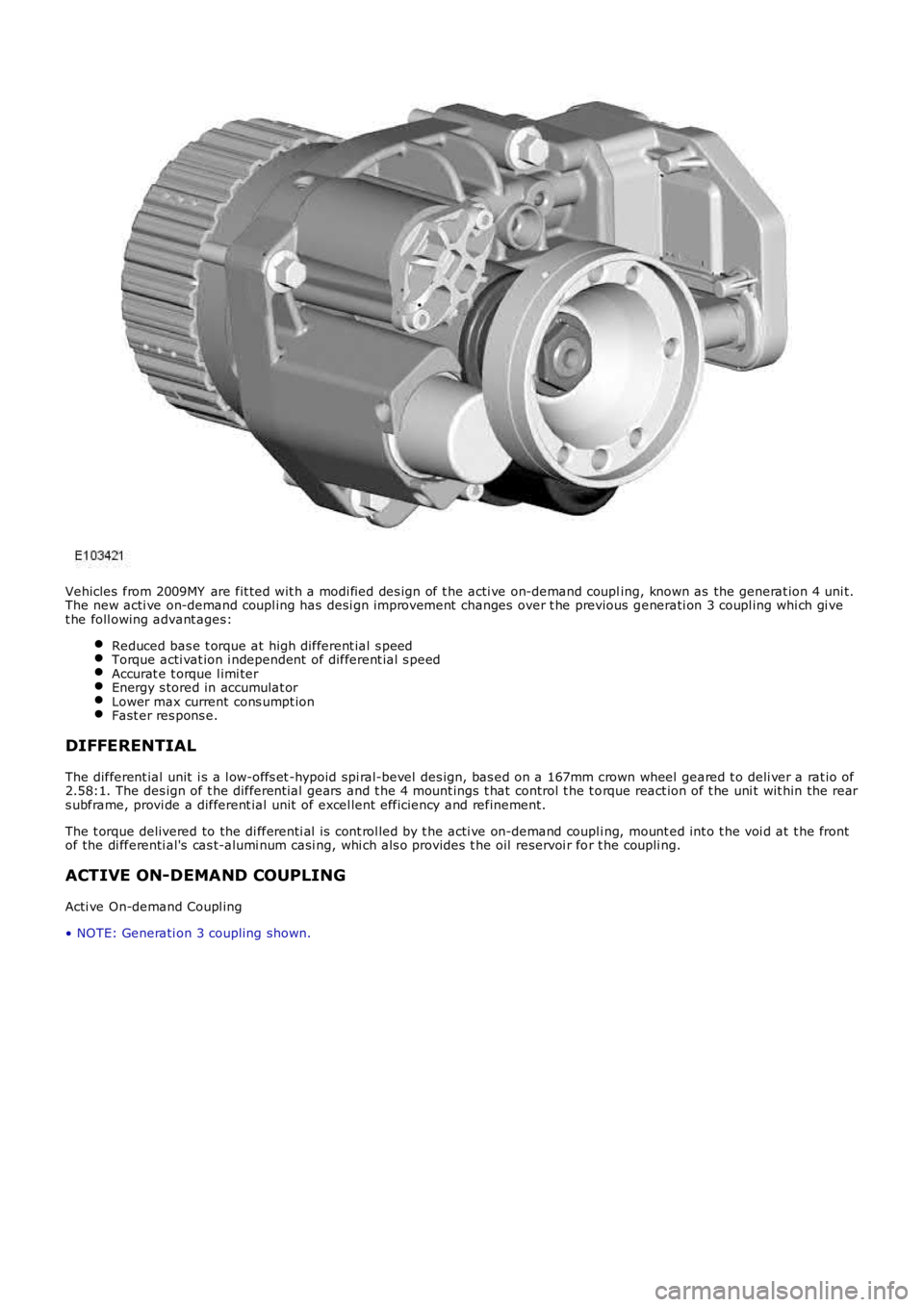
Vehicles from 2009MY are fit ted wit h a modi fied des ign of t he acti ve on-demand coupling, known as the generat ion 4 uni t.The new acti ve on-demand coupl ing has desi gn improvement changes over t he previous generati on 3 coupl ing whi ch gi vet he foll owing advant ages:
Reduced bas e t orque at high different ial s peedTorque acti vat ion i ndependent of different ial s peedAccurat e t orque l imi terEnergy s tored in accumulat orLower max current cons umpt ionFast er res pons e.
DIFFERENTIAL
The different ial unit i s a l ow-offs et -hypoid spi ral-bevel des ign, bas ed on a 167mm crown wheel geared t o deli ver a rat io of2.58:1. The des ign of t he different ial gears and t he 4 mount ings t hat control t he t orque react ion of t he uni t wit hin the rears ubframe, provi de a different ial unit of excel lent efficiency and refinement.
The t orque delivered to the di fferenti al i s cont rol led by t he acti ve on-demand coupli ng, mount ed int o t he voi d at t he frontof the di fferenti al's cas t-alumi num casi ng, whi ch als o provi des t he oil reservoi r for t he coupli ng.
ACTIVE ON-DEMAND COUPLING
Acti ve On-demand Coupl ing
• NOTE: Generati on 3 coupling shown.
Page 321 of 3229
Not s ens it ive to brake tes ti ng on a chas si s dynamomet er.
Generati on 4 Acti ve On-Demand Coupli ng - Vehicles from 2009MY
The generati on 4 coupl ing does not have the di fferenti al s peed dri ven pump used on the previ ous generat ion 3coupl ing, but i s fit ted wi th a bigger capacit y electrically operated axial pump and a hi gh pres s ure accumul ator.The proport ional throt t le valve and press ure s ens or on t he generat ion 3 coupli ng is replaced wit h a proport ionalpres s ure reducing val ve.The t orque li mit er pres sure reducing valve on the generat ion 3 coupli ng is replaced by an electroni c cont rol valveand cont rol ling software.
The generati on 4 acti ve on-demand coupli ng gives t he fol lowing improvements over t he previous generati on 3 coupl ing:
Reduced bas e t orque at high different ial s peedsTorque acti vat ion i s now i ndependent of different ial s peedAccurat e t orque l imi ter cont rolEnergy s tored in hi gh pres s ure accumul ator givi ng a low maximum current consumpt ion of t he electric pump andfas t er res pons e.
Control Module - G eneration 3 and 4 Couplings
The cont rol module, at tached to the cas ing of t he act ive on-demand coupling, forms a s ingle unit wit h t he cont rolvalve/axial s ol enoi d. By anal yzi ng informat ion from other vehi cl e modules and s ensors t he cont rol module regul ates t heaxial sol enoi d t o cont rol t he hydraul ic flui d pres s ure s uppl ied t o t he clut ch pl ates. Some of t he modul es and s ens ors thecont rol module communi cat es wit h are li s ted below:
Hardwi red:- Control valve / axi al s olenoid- Electric hydrauli c pump- Oi l press ure and temperat ure sens orHigh speed CAN (cont rol ler area net work):- Engine cont rol module- Anti -l ock brake s ys t em / t racti on cont rol module- Tracti on res ponse swit ch- Y aw rate sens or- Steering wheel rot at ion sens or
The axial sol enoi d cons t ant ly adjust s t he cont rol valve output us ing a Pul se W i dt h Modulat ion (PW M) s i gnal. The flui dpres s ure deli vered t o t he cl utch plat es determines t he amount of t orque t hat is delivered t o t he rear axl e.
The act ive on-demand coupli ng has int egrated oi l press ure and temperature s ens ors to enable the control modul e t oaccurat ely manage t he t orque t ransfer under all environment al and operat ing condit ions . Usi ng thes e s ignals the controlmodule will us e s t rategi es to protect the coupli ng from overheati ng; in extreme cas es to protect t he coupli ng from damaget he coupli ng wil l dis engage i f the t emperat ure of t he hydraul ic flui d exceeds 105°C. The coupl ing wi ll ret urn to normalfuncti onal it y when t he temperat ure fall s below 101°C.
The cont rol module has an int egrated di agnos ti cs sys tem, whi ch cons tant ly moni tors the act ive on-demand couplings ys t em as wel l as it s input and output s ignals . If t he control modul e detects a fault a Diagnost ic Troubl e Code (DTC) i ss tored. The DTC is acces s ed usi ng t he Land Rover approved di agnos t ic s yst em.
Electric Hydraulic Pump
W hen negoti ati ng very low frict ion s urfaces s uch as wet gras s , snow or i ce; i nit ial wheel -s pin can cut i nt o t he s urface andreduce gri p. W it h a re-act ive on-demand coupl ing, almos t 60 degrees of wheel rotat ion woul d occur before torque could bet ransmit ted t hrough t he coupl ing.
On Generat ion 3 coupli ngs , t o count eract thi s Land Rover devel oped a uni que high-pres s ure pre-charge faci li ty whi chenergizes t he hydraul ic circui t as s oon as the engi ne is s t art ed. Es s ent ial ly an el ect ri cal ly operat ed hydraul ic pump wasdesi gned to maintai n a pot ent ial of 500 Nm (369 l b ft ) of t orque pres s ure wi thi n the coupli ng. (This pre-charge t orquecapacit y has been increas ed to 1500Nm (1106 l b ft ) for t he Generat ion 4 coupli ng.)
Vehicles fit ted wi th Terrai n Res pons e als o add furt her benefi ts by varying t he level of pre-charge t o deli ver opti mumt racti on over a range of di fferent t errai n s urfaces . The level of pre-charge is varied dependi ng on t he part icul ar terrainres ponse mode, for exampl e:
Terrai n respons e in 'Speci al Programs Off' mode as common wit h vehi cl es wit hout terrain res pons e, the coupli ng isprogrammed t o transmit 500 Nm 369 lb ft of t orque on Generat ion 3 couplings and 1500 Nm (1106 l b ft) of t orqueon Generat ion 4 couplings t o t he rear axle when the vehicle moves from res t i n a s t raight l ine. Thi s s trategymi ni mi zes t ract ion l os s from a s t andi ng-s tart regardles s of t he terrain. W hen the vehicle accelerat es the pres surein the coupling is decreas ed to improve fuel economy.The abili ty to sens e t he s teeri ng angl e all ows t he coupli ng t o be programmed t o provide no torque trans fer t hrought he coupli ng. This prevent s t he coupli ng locking when t he vehicle i s maneuvring at low s peeds and acute s teeri ngangl es.In 'Grass / Gravel / Snow' mode t he coupl ing i s programmed to maint ai n i ts pre-charge s t at e unt il much highers peeds are obtained. The s ame applies even i f the vehicle is t raveli ng at low speeds and acut e s t eering angles , ast racti on takes precedence over coupli ng lock-up on l ow-fri ct ion s urfaces .
For addit ional informat ion, refer t o: Ride and Handli ng Opti mizat ion (204-06 Ride and Handli ng Opt imi zat ion, Descripti onand Operat ion).
Mechanical Hydraulic Pump - Generation 3 Couplings - Vehicles up to 2009MY
The dri ves haft i s att ached t o t he coupl ing's front clut ch pl ate as s embly (i nput ), with the rear cl ut ch plat e as sembl yconnected t o t he different ial pini on (out put ). A s was h-pl ate wit h 6 hydrauli c rol lers is al so att ached t o t he different ialpinion. W hen there is no s peed difference bet ween the coupling's input and out put, the rol lers do not funct ion.