2006 LAND ROVER FRELANDER 2 wheel torque
[x] Cancel search: wheel torquePage 540 of 3229
diamet er in i ts central sect ion. The smal ler diamet er allows the t ors ion bar t o t wist in res pons e t o t orque appli ed from t hes teeri ng wheel in relati on t o t he grip of the t yres on t he road surface. The pi nion s haft has machined t eet h on it s cent raldiamet er whi ch mat e wit h t eeth on the s t eering gear rack. A s lot , machi ned in t he upper end of t he pini on s haft mateswit h t he dog-t oot h on the i nput s haft . The pinion s haft l ocat es in the pi ni on housi ng and rot ates on bal l and roll erbearings .
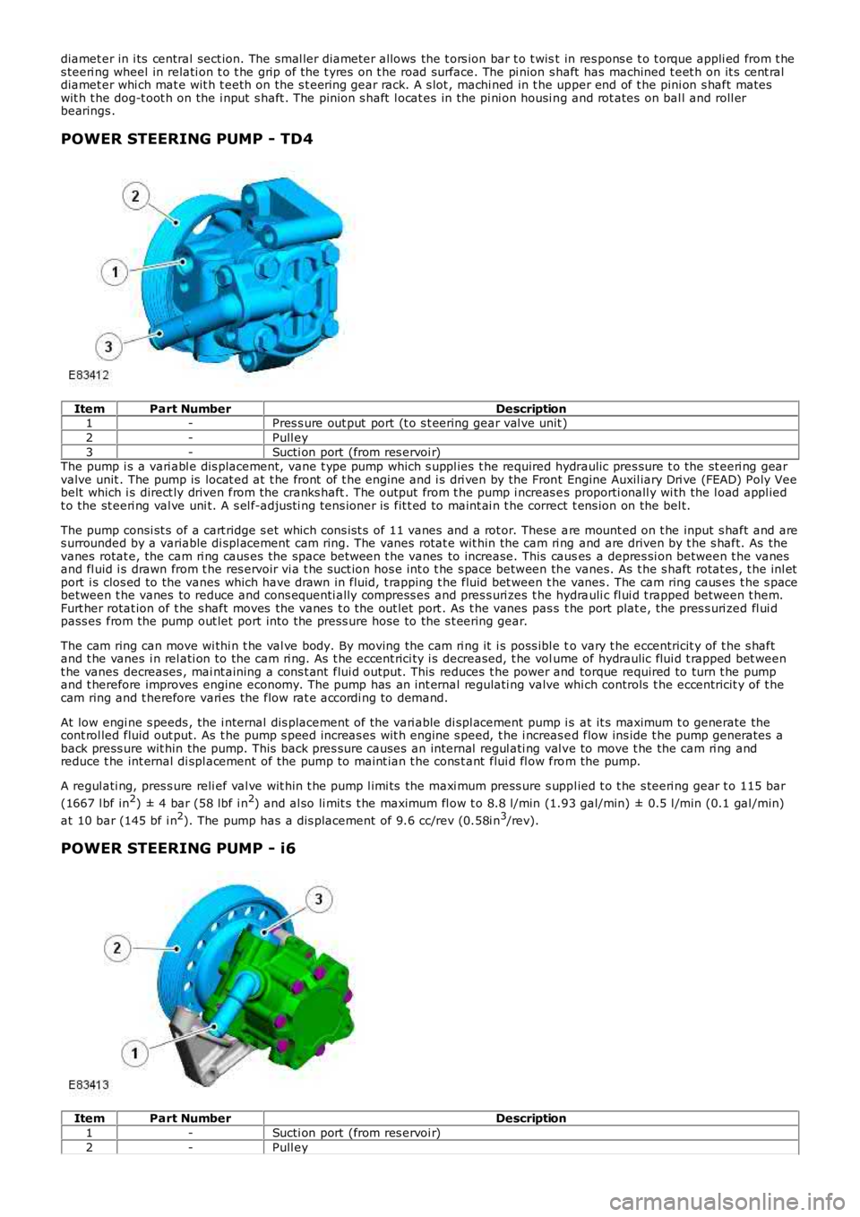
POWER STEERING PUMP - TD4
ItemPart NumberDescription1-Pres s ure out put port (t o s t eering gear val ve unit )
2-Pull ey
3-Sucti on port (from res ervoi r)The pump i s a vari abl e dis placement, vane t ype pump which s uppl ies t he required hydraulic pres sure t o the st eeri ng gearvalve unit . The pump is locat ed at t he front of t he engine and i s dri ven by the Front Engine Auxil iary Dri ve (FEAD) Poly Veebelt which i s direct ly driven from the cranks haft . The out put from t he pump i ncreas es proporti onall y wi th the l oad appl iedt o the st eeri ng val ve uni t. A s el f-adjus ti ng tens ioner is fit t ed to maint ai n t he correct t ens ion on the bel t.
The pump consi st s of a cart ridge s et which cons is t s of 11 vanes and a rot or. These are mount ed on t he input s haft and ares urrounded by a variable di spl acement cam ring. The vanes rotat e wit hin the cam ri ng and are driven by t he s haft. As thevanes rotat e, the cam ri ng caus es the space between t he vanes to increase. This causes a depres si on between t he vanesand fl uid i s drawn from t he res ervoir vi a t he suct ion hos e int o t he s pace between the vanes. As t he s haft rotat es , t he inl etport i s clos ed to the vanes which have drawn in fluid, t rapping t he fluid bet ween t he vanes . The cam ring caus es t he s pacebetween t he vanes to reduce and cons equenti ally compress es and pres s uri zes t he hydrauli c fl ui d t rapped between t hem.Furt her rotat ion of t he s haft moves the vanes t o the out let port . As t he vanes pas s t he port plat e, the pres s uri zed fl ui dpass es from the pump out let port into the press ure hose to the s t eering gear.
The cam ring can move wi thi n t he val ve body. By moving the cam ri ng it i s poss ibl e to vary t he eccentricit y of t he s haftand t he vanes i n rel ati on to the cam ri ng. As t he eccent rici ty i s decreased, t he volume of hydraulic flui d t rapped bet weent he vanes decreases , mai nt aining a cons t ant flui d output. This reduces t he power and torque required to turn t he pumpand t herefore improves engine economy. The pump has an int ernal regulati ng valve which controls t he eccentricit y of t hecam ring and t herefore vari es the flow rat e accordi ng to demand.
At low engi ne s peeds , the i nternal dis placement of the vari able di spl acement pump i s at it s maximum t o generate thecont rol led fluid out put. As t he pump s peed increas es wit h engine s peed, t he i ncreas ed flow ins ide t he pump generates aback press ure wit hin the pump. This back pres s ure causes an internal regul ati ng val ve to move t he the cam ri ng andreduce t he int ernal di spl acement of the pump to maint ian t he cons t ant flui d fl ow from the pump.
A regul ati ng, pres s ure reli ef val ve wit hin t he pump l imi ts the maxi mum press ure s uppl ied t o t he s teeri ng gear t o 115 bar
(1667 l bf in2) ± 4 bar (58 lbf i n2) and al so li mit s t he maximum fl ow t o 8.8 l/min (1.93 gal/min) ± 0.5 l /min (0.1 gal /min)
at 10 bar (145 bf i n2). The pump has a dis placement of 9.6 cc/rev (0.58i n3/rev).
POWER STEERING PUMP - i6
ItemPart NumberDescription
1-Sucti on port (from res ervoi r)
2-Pull ey
Page 570 of 3229
Publi s hed: 11-May-2011
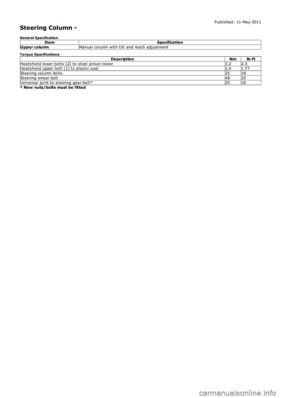
Steering Column -
General SpecificationItemSpecification
Upper columnManual column wit h t ilt and reach adjust ment
Torque Specifications
DescriptionNmlb-ft
Heats hiel d lower bolt s (2) to s t eel pi ni on t ower3.22.3Heats hiel d upper bolt (1) t o plas ti c s eal2.41.77
St eering column bol ts2518
St eering wheel bol t4835Univers al joi nt to st eering gear bolt *2518
* New nuts/bolts must be fitted
Page 604 of 3229
DescriptionNmlb-ft
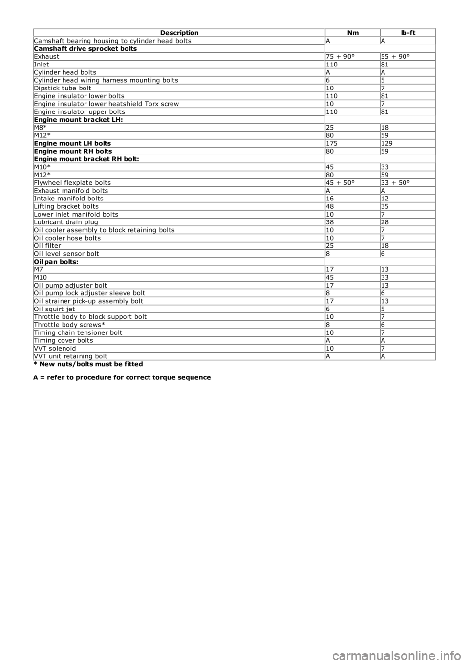
Cams haft beari ng hous ing to cyli nder head bolt sAA
Camshaft drive sprocket boltsExhaus t75 + 90°55 + 90°
Inlet11081
Cyli nder head bolt sAACyli nder head wiring harnes s mount ing bolt s65
Di ps t ick t ube bol t107
Engine i ns ulat or lower bolt s11081Engine i ns ulat or lower heat s hield Torx s crew107
Engine i ns ulat or upper bolt s11081
Engine mount bracket LH:M8*2518
M12*8059
Engine mount LH bolts175129Engine mount RH bolts8059
Engine mount bracket RH bolt:
M10*4533M12*8059
Flywheel flexplat e bolt s45 + 50°33 + 50°
Exhaus t manifold bol tsAAIntake manifold bol ts1612
Lifti ng bracket bol ts4835
Lower inlet mani fold bol ts107Lubricant drain plug3828
Oi l cooler as sembl y t o block ret aining bol ts107
Oi l cooler hos e bolt s107Oi l fil ter2518
Oi l level s ensor bolt86
Oil pan bolts:M71713
M104533
Oi l pump adjus ter bolt1713Oi l pump lock adjus ter s leeve bolt86
Oi l st rai ner pi ck-up ass embly bol t1713
Oi l squirt jet65Throt tl e body to block support bolt107
Throt tl e body s crews*86
Timing chain t ensi oner bolt107Timing cover bolt sAA
VVT s olenoid107
VVT unit retai ni ng boltAA* New nuts/bolts must be fitted
A = refer to procedure for correct torque sequence
Page 753 of 3229
DescriptionNmlb-ft
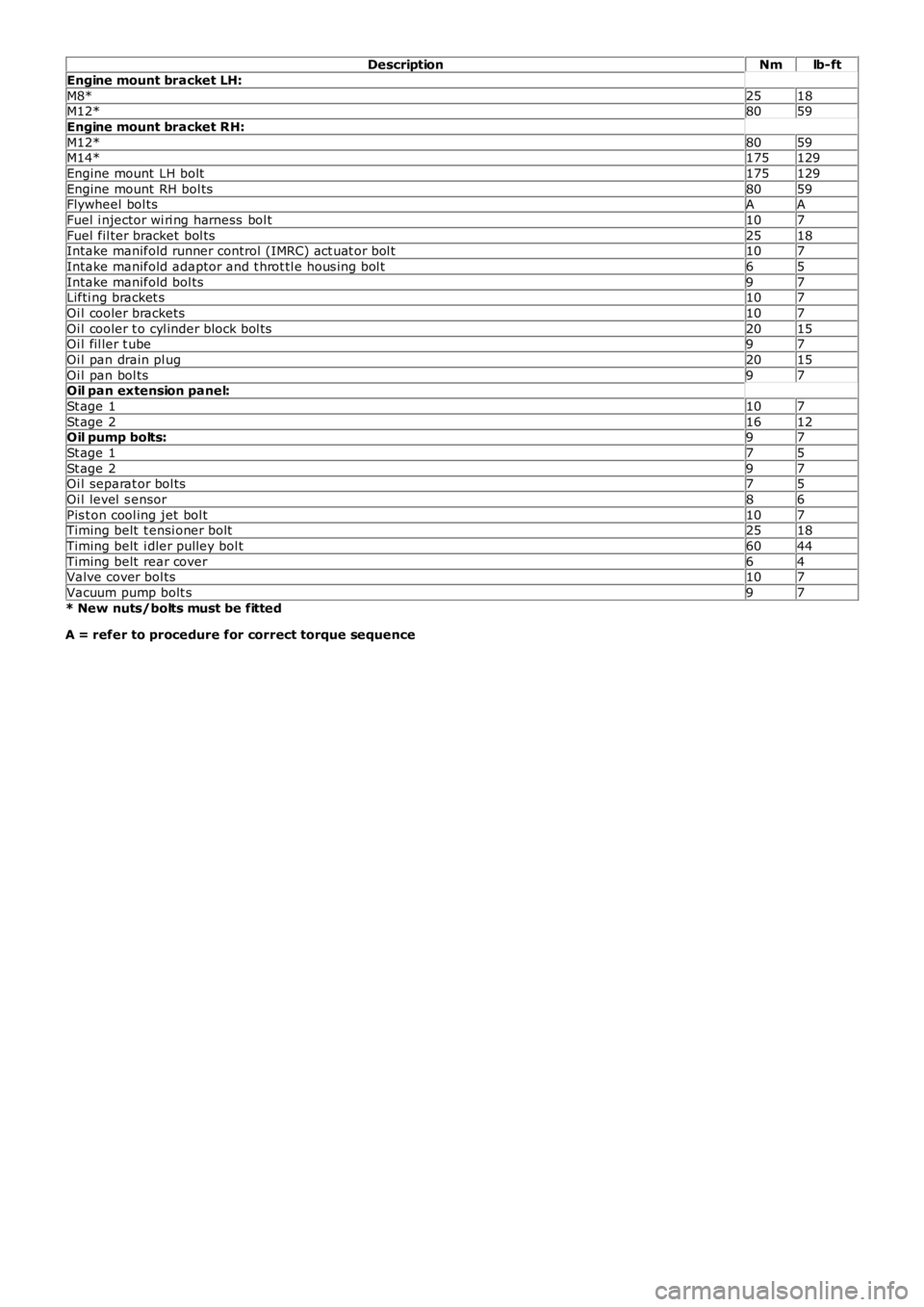
Engine mount bracket LH:
M8*2518M12*8059
Engine mount bracket RH:
M12*8059M14*175129
Engine mount LH bolt175129
Engine mount RH bol ts8059Flywheel bol tsAA
Fuel i njector wi ri ng harness bol t107
Fuel fil ter bracket bol ts2518Intake manifold runner control (IMRC) act uat or bol t107
Intake manifold adaptor and t hrot tl e hous i ng bol t65
Intake manifold bol ts97Lifti ng bracket s107
Oi l cooler brackets107
Oi l cooler t o cyl inder block bol ts2015Oi l fil ler t ube97
Oi l pan drain pl ug2015
Oi l pan bol ts97Oil pan extension panel:
St age 1107
St age 21612Oil pump bolts:97
St age 175
St age 297Oi l separat or bol ts75
Oi l level s ensor86
Pis t on cool ing jet bol t107Timing belt t ensi oner bolt2518
Timing belt i dler pulley bol t6044
Timing belt rear cover64Valve cover bol ts107
Vacuum pump bolt s97
* New nuts/bolts must be fitted
A = refer to procedure for correct torque sequence
Page 770 of 3229
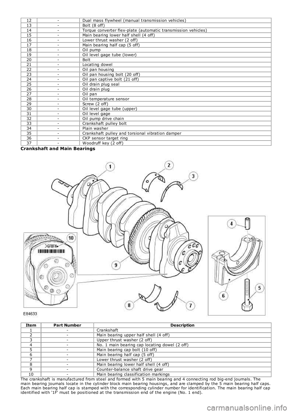
12-Dual mas s flywheel (manual t rans mi ss i on vehi cl es )
13-Bol t (8 off)
14-Torque convert er flex-pl ate (automat ic trans mi ss i on vehi cl es)15-Mai n beari ng lower half s hel l (4 off)
16-Lower t hrus t washer (2 off)
17-Mai n beari ng hal f cap (5 off)18-Oil pump
19-Oil level gage tube (lower)
20-Bol t21-Locati ng dowel
22-Oil pan hous i ng
23-Oil pan hous i ng bol t (20 off)24-Oil pan capt ive bolt (21 off)
25-Oil drai n plug s eal
26-Oil drai n plug27-Oil pan
28-Oil t emperature s ens or
29-Screw (2 off)30-Oil level gage tube (upper)
31-Oil level gage
32-Oil pump drive chai n33-Cranks haft pull ey bolt
34-Pl ain was her
35-Cranks haft pull ey and t ors ional vi brati on damper36-CKP sens or target ring
37-W oodruff key (2 off)
Crankshaft and Main Bearings
ItemPart NumberDescription
1-Cranks haft2-Mai n bearing upper half s hel l (4 off)
3-Upper thrust was her (2 off)
4-No. 1 main beari ng cap locati ng dowel (2 off)5-Mai n bearing cap bol t (10 off)
6-Mai n bearing hal f cap (5 off)
7-Lower thrust was her (2 off)8-Mai n bearing lower hal f s hel l (4 off)
9-Counter-balance s haft dri ve gear
10-Mai n bearing cl ass ificati on marki ngsThe crankshaft is manufact ured from st eel and formed wit h 5 main beari ng and 4 connect ing rod big-end journals . Themain bearing journals l ocat e in the cyli nder bl ock mai n beari ng hous ings , and are clamped by the 5 main bearing half caps.Each main beari ng half cap is st amped wi th t he corresponding cylinder number for identi fi cat ion. The main bearing half capidenti fi ed wit h '1F' mus t be pos it ioned at the trans mi ss i on end of the engine (No. 1 end).
Page 1026 of 3229
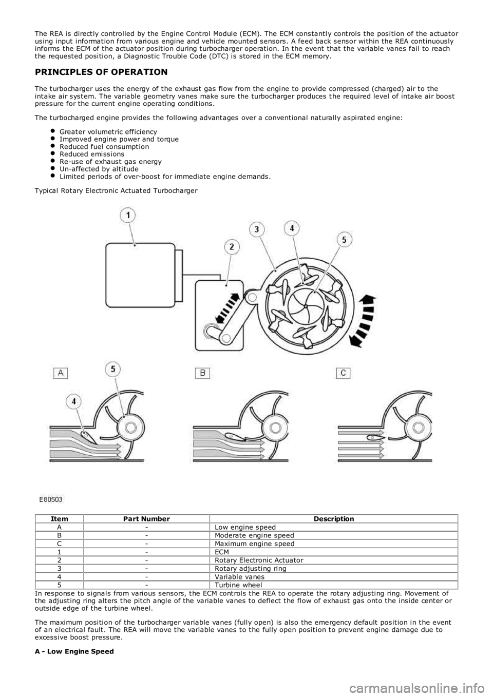
The REA i s direct ly controlled by the Engine Cont rol Modul e (ECM). The ECM cons tantly cont rol s t he pos i ti on of the actuat orus ing i nput i nformat ion from vari ous engine and vehicle mounted s ensors . A feed back s ens or wi thin the REA cont inuous lyinforms the ECM of t he actuat or pos it ion during t urbocharger operat ion. In the event that t he variable vanes fail to reacht he request ed posi ti on, a Diagnost ic Troubl e Code (DTC) i s s tored in the ECM memory.
PRINCIPLES OF OPERATION
The t urbocharger us es the energy of t he exhaus t gas fl ow from the engi ne to provide compres s ed (charged) air t o theint ake air s ys t em. The variable geomet ry vanes make s ure the turbocharger produces the required level of intake ai r boos tpres s ure for the current engi ne operati ng condit ions .
The t urbocharged engine provi des the foll owing advant ages over a convent ional nat urall y as pi rat ed engi ne:
Great er vol umet ric efficiencyImproved engi ne power and torqueReduced fuel consumpt ionReduced emi ss i onsRe-us e of exhaus t gas energyUn-affected by al ti tudeLimi ted periods of over-boos t for immediate engi ne demands .
Typi cal Rot ary Electronic Actuat ed Turbocharger
ItemPart NumberDescription
A-Low engine s peedB-Moderate engi ne s peed
C-Maximum engi ne s peed
1-ECM2-Rotary Electroni c Actuator
3-Rotary adjus ti ng ri ng
4-Vari abl e vanes5-Turbine wheel
In res pons e to s i gnal s from vari ous s ens ors , t he ECM cont rol s t he REA t o operate the rotary adjus ti ng ri ng. Movement oft he adjust ing ri ng alt ers t he pit ch angl e of the variable vanes t o deflect t he fl ow of exhaus t gas ont o t he i ns i de cent er orouts ide edge of t he t urbine wheel.
The maximum posi ti on of the turbocharger variable vanes (full y open) is als o the emergency default pos it ion i n t he eventof an electrical fault . The REA wil l move t he variable vanes t o t he ful ly open posi ti on t o prevent engi ne damage due toexces s ive boost press ure.
A - Low Engine Speed
Page 1078 of 3229
informat ion read by the manufact urer approved diagnos t ic s ys tem).
• NOTE: W hen performing volt age or res is t ance t est s , always use a digi tal mult imeter (DMM) accurat e t o 3 decimal places,and wit h an up-to-dat e cali brati on cert ificat e. W hen t est ing res is tance, al ways take t he res i st ance of t he DMM leads int oaccount.
• NOTE: Check and recti fy bas ic faul ts before beginni ng diagnos t ic rout ines i nvol vi ng pinpoint t es t s.
• NOTE: If DTCs are recorded and, aft er performi ng the pi npoi nt tes ts , t he fault i s not pres ent , an i nt ermit tent concernmay be t he cause. Always check for loos e connecti ons and corroded t ermi nal s.
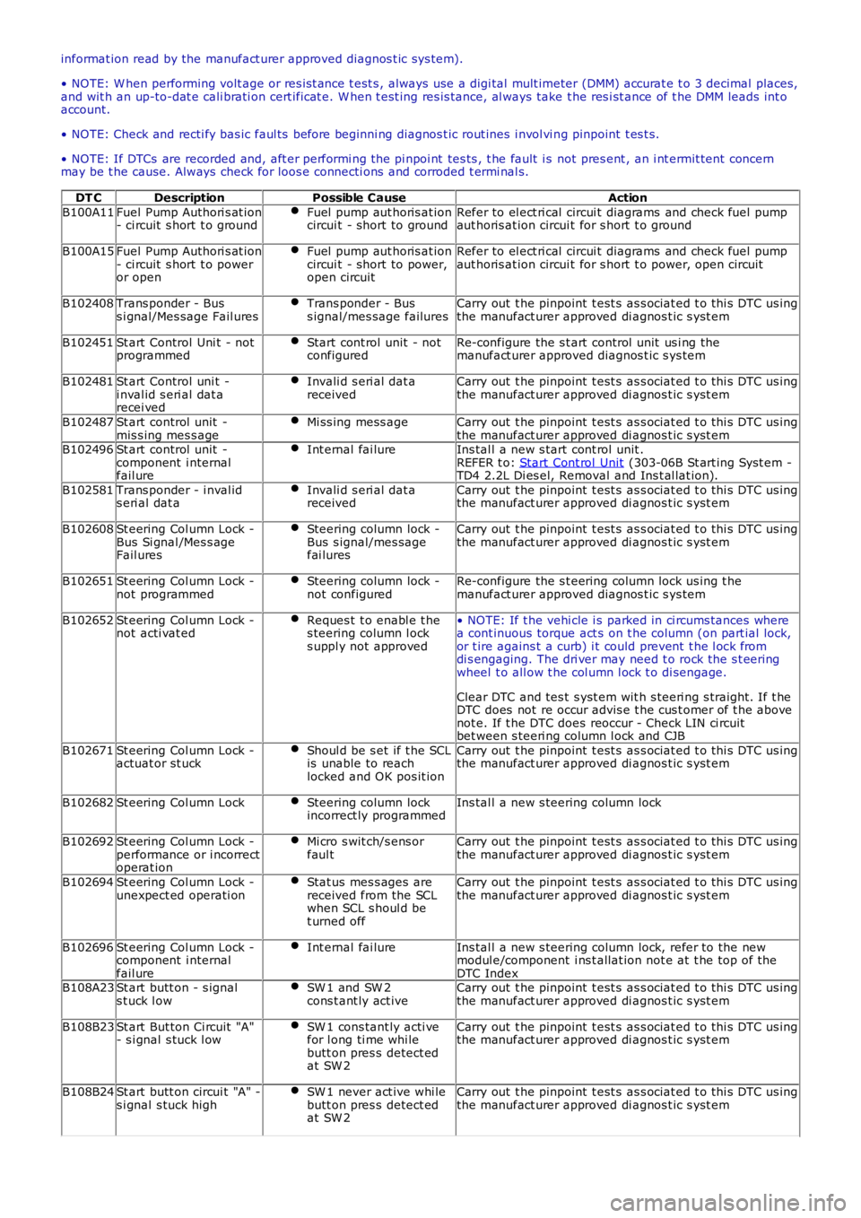
DT CDescriptionPossible CauseAction
B100A11Fuel Pump Authori s at ion- ci rcuit s hort t o groundFuel pump aut horis at ioncircui t - short to groundRefer to el ect ri cal circui t diagrams and check fuel pumpaut horis at ion circui t for s hort t o ground
B100A15Fuel Pump Authori s at ion- ci rcuit s hort t o poweror open
Fuel pump aut horis at ioncircui t - short to power,open circuit
Refer to el ect ri cal circui t diagrams and check fuel pumpaut horis at ion circui t for s hort t o power, open circuit
B102408Trans ponder - Buss i gnal/Mes sage Fail uresTrans ponder - Buss ignal/mes sage failuresCarry out t he pinpoint t est s as s ociat ed t o t hi s DTC us ingthe manufact urer approved di agnos t ic s yst em
B102451St art Control Uni t - notprogrammedStart cont rol unit - notconfiguredRe-configure the s t art control unit us i ng themanufact urer approved diagnos t ic s ys tem
B102481St art Control uni t -i nval id s eri al dat arecei ved
Invali d s eri al dat areceivedCarry out t he pinpoint t est s as s ociat ed t o t hi s DTC us ingthe manufact urer approved di agnos t ic s yst em
B102487St art control unit -mis s ing mes s ageMi ss ing mess ageCarry out t he pinpoint t est s as s ociat ed t o t hi s DTC us ingthe manufact urer approved di agnos t ic s yst emB102496St art control unit -component i nternalfail ure
Int ernal fai lureIns tal l a new s tart cont rol unit .REFER t o: Start Cont rol Unit (303-06B St art ing Syst em -TD4 2.2L Di es el, Removal and Ins t al lat ion).
B102581Trans ponder - i nval ids eri al dat aInvali d s eri al dat areceivedCarry out t he pinpoint t est s as s ociat ed t o t hi s DTC us ingthe manufact urer approved di agnos t ic s yst em
B102608St eering Col umn Lock -Bus Si gnal /Mes s ageFail ures
Steering column lock -Bus s ignal/mes sagefai lures
Carry out t he pinpoint t est s as s ociat ed t o t hi s DTC us ingthe manufact urer approved di agnos t ic s yst em
B102651St eering Col umn Lock -not programmedSteering column lock -not configuredRe-configure the s t eering column lock us ing t hemanufact urer approved diagnos t ic s ys tem
B102652St eering Col umn Lock -not acti vat edReques t t o enabl e t hes teering column l ocks uppl y not approved
• NOTE: If t he vehi cle i s parked in ci rcums tances wherea cont inuous torque act s on t he column (on part ial lock,or t ire agains t a curb) i t could prevent t he l ock fromdi s engaging. The dri ver may need t o rock the s t eeringwheel t o all ow t he col umn l ock t o di sengage.
Clear DTC and tes t s yst em wit h s teeri ng s traight. If t heDTC does not re occur advis e t he cus t omer of t he abovenot e. If t he DTC does reoccur - Check LIN ci rcuitbet ween s teeri ng column l ock and CJB
B102671St eering Col umn Lock -actuat or st uckShoul d be s et if t he SCLis unable to reachlocked and OK pos it ion
Carry out t he pinpoint t est s as s ociat ed t o t hi s DTC us ingthe manufact urer approved di agnos t ic s yst em
B102682St eering Col umn LockSteering column lockincorrect ly programmedIns tal l a new s teering column lock
B102692St eering Col umn Lock -performance or i ncorrectoperat ion
Mi cro s wit ch/s ens orfaul tCarry out t he pinpoint t est s as s ociat ed t o t hi s DTC us ingthe manufact urer approved di agnos t ic s yst em
B102694St eering Col umn Lock -unexpect ed operati onStat us mes s ages arereceived from the SCLwhen SCL s houl d bet urned off
Carry out t he pinpoint t est s as s ociat ed t o t hi s DTC us ingthe manufact urer approved di agnos t ic s yst em
B102696St eering Col umn Lock -component i nternalfail ure
Int ernal fai lureIns tal l a new s teering column lock, refer to the newmodul e/component i ns t allat ion not e at t he top of t heDTC IndexB108A23St art butt on - s ignals t uck l owSW 1 and SW 2cons t ant ly act iveCarry out t he pinpoint t est s as s ociat ed t o t hi s DTC us ingthe manufact urer approved di agnos t ic s yst em
B108B23St art But ton Ci rcuit "A"- s i gnal s tuck l owSW 1 cons tant ly acti vefor l ong ti me whi lebutt on pres s detect edat SW 2
Carry out t he pinpoint t est s as s ociat ed t o t hi s DTC us ingthe manufact urer approved di agnos t ic s yst em
B108B24St art butt on circui t "A" -s i gnal s tuck highSW 1 never act ive whi lebutt on pres s detect edat SW 2
Carry out t he pinpoint t est s as s ociat ed t o t hi s DTC us ingthe manufact urer approved di agnos t ic s yst em
Page 1195 of 3229
Publi s hed: 11-May-2011
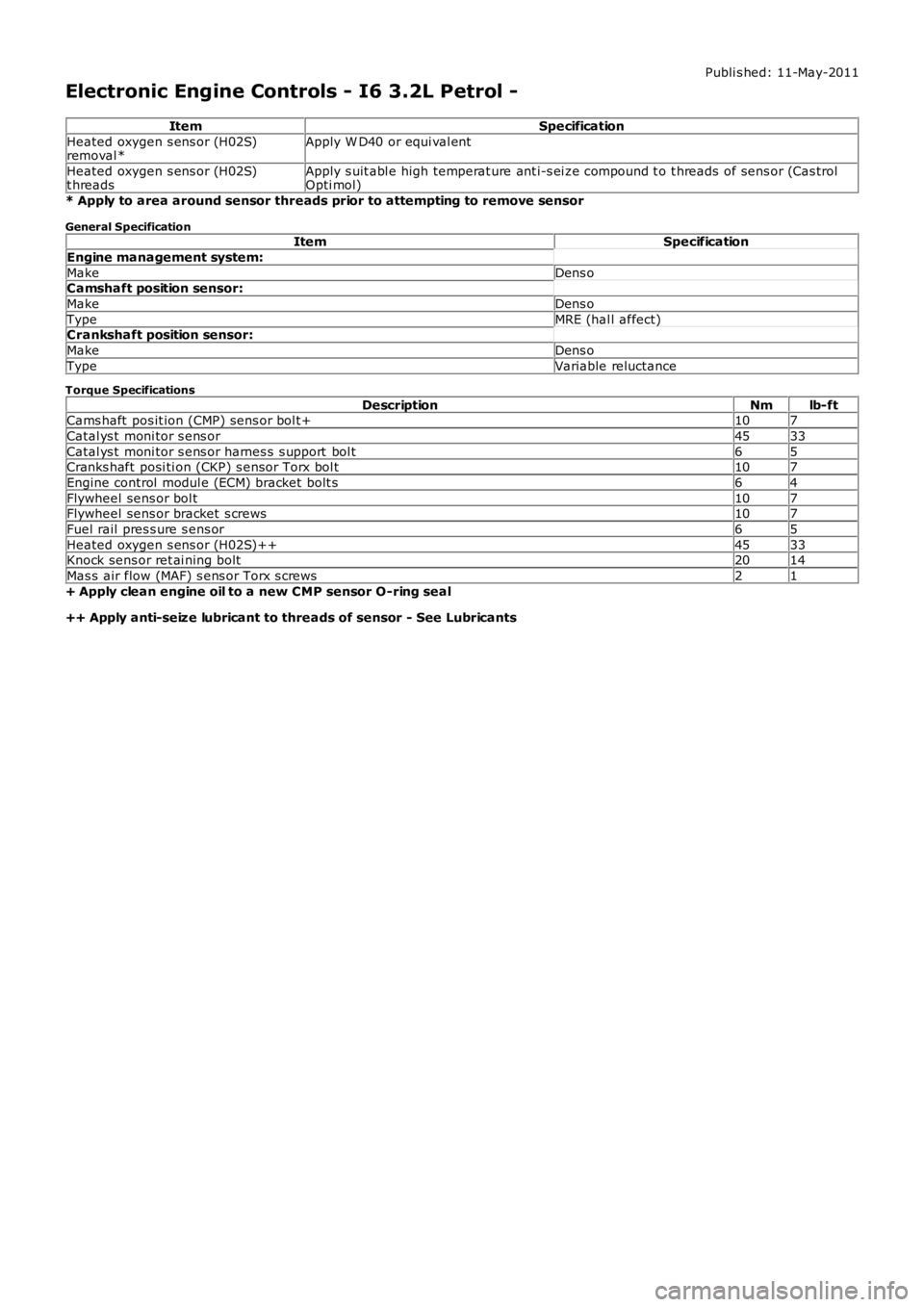
Electronic Engine Controls - I6 3.2L Petrol -
ItemSpecification
Heated oxygen s ens or (H02S)removal *Apply W D40 or equi val ent
Heated oxygen s ens or (H02S)t hreadsApply s uit abl e high temperat ure ant i-s ei ze compound t o t hreads of sens or (Cas trolOpti mol)
* Apply to area around sensor threads prior to attempting to remove sensor
General SpecificationItemSpecification
Engine management system:
MakeDens oCamshaft position sensor:
MakeDens o
TypeMRE (hal l affect)Crankshaft position sensor:
MakeDens o
TypeVariable reluctance
Torque Specifications
DescriptionNmlb-ftCams haft pos it ion (CMP) sens or bol t+107
Catal ys t moni tor s ens or4533
Catal ys t moni tor s ens or harnes s s upport bol t65Cranks haft posi ti on (CKP) s ensor Torx bol t107
Engine control modul e (ECM) bracket bolt s64
Flywheel sens or bol t107Flywheel sens or bracket s crews107
Fuel rail pres s ure s ens or65
Heated oxygen s ens or (H02S)++4533Knock sens or ret ai ning bolt2014
Mas s air flow (MAF) s ens or Torx s crews21
+ Apply clean engine oil to a new CMP sensor O-ring seal
++ Apply anti-seize lubricant to threads of sensor - See Lubricants