2006 LAND ROVER FRELANDER 2 wheel torque
[x] Cancel search: wheel torquePage 322 of 3229
However, when the front and rear axl es st art t o rotat e at different s peeds , t he s wash-pl ate rot at es rel ati ve to the roll erswhich generat es the hydrauli c pres s ure. Thi s pres s ure i s us ed to force the opposi ng clut ch pl ates t oget her, i ncreas ing thet ransmis s ion of t orque t o the rear axl e. As the di fference in axl e s peed i ncreases the hydrauli c pres sure pushes t he clut chplat es further together t o increas e t he t orque to the rear axl e.
A control val ve/axi al s olenoid cont rols the amount of pres s ure appli ed to the clut ch plat es , and hence the amount oft orque transmit ted t o t he rear wheels . Clos e manufact uring t olerances and except ional ly low component wear ens uret orque cont rol remai ns accurat e t hroughout t he vehi cl e's l ife.
Mechanical Hydraulic Pump - Generation 4 Couplings - Vehicles from 2009MY
The Generati on 4 coupl ing does not us e the swas h pl at e t o mechanical ly rais e hydrauli c pres s ure; ins tead, a new hydraul icpump i s used to generat e hydrauli c pres sure and force the cl utch plat es toget her. The removal of t he s was h plat e all ows alarger overal l cl ut ch plat e s urface area, whi ch in t urn reduces t he hydrauli c pres sure requi rement. The press ure required toachi eve 1500Nm (1106 l b ft ) has been reduced from 100 Bar for Generat ion 3 coupli ngs to 40 Bar for Generati on 4coupl ings.
The posi ti oni ng of the Generat ion 4 coupl ing's i nput and output remains t he s ame as t he Generati on 3 coupl ing, asdescribed above.
By-pass Valve
On very low fricti on s urfaces, driveli ne drag t orque can occur, for exampl e:
revers e t orque from engi ne braking, orforced movement of t he dri ves haft by t he front wheel s .
This can i nfluence rear wheel s peed, maki ng it i mpos si ble t o determine the t rue fricti on capabil it y of the rear wheel s, bydis t orti ng t he wheel s peed s ignal. To prevent thi s, t he acti ve on-demand coupli ng is des i gned t o open i mmediat el y inres ponse to a s tabil it y cont rol event . This i s achi eved by a by-pass val ve ins tant ly reducing sys tem pres s ure t o nomi nal .
To balance the 4 bar bas e press ure (s ee below for detai ls ), t he Generati on 3 coupling us es a large Bel levill e s pri ng to forcet he cl utch plat es clear of each ot her t o prevent torque transmis si on t hrough the coupli ng. Even at 0°C, t orque t rans mis s ionis reduced from 300 Nm to Zero wi thi n 10 ms . The Generat ion 4 coupling however, does not require a Bel lvil le s pri ng t os eparate t he plat es as t he coupli ng does not have a si gni fi cant bas e pres s ure pus hi ng t he plates together.
Accumulator
The further t he cl utch pl at es have to move in order to contact each other, t he longer it t akes to di spl ace the hydrauli c fl uidneces s ary t o buil d pres s ure and t rans mit torque. To count er thi s, t he Generati on 3 coupling incorporates an accumulat or.This retains a nominal 4 bar pres sure wi thin the hydraul ic circui t. Al though thi s is not enough pres sure t o caus e s i gni fi cantt orque transmis s ion t hrough the coupli ng, i t forces t he plat es very clos e t oget her so that very l it tl e fluid di s pl acement i srequired t o achi eve full engagement and maxi mum t orque t rans fer. Ful l torque t rans miss i on can be achieved i n 150 ms .
On Generat ion 4 coupli ngs , t he 150ms act ivat ion t ime is achieved through the us e of a Bel lvil le s pri ng t hat acts to pus ht he plates t ogether (wi thout caus i ng si gnifi cant t orque t rans mis s ion t hrough t he coupl ing). As t he pump i s notcont inuousl y us ed to create t his bas e pres s ure (as i t was wit h Generat ion 3 coupli ng), improvement s i n fuel economy havebeen achi eved.
Wet Clutch Pack
The clutch pack is made up of 7 pairs of plat es ; t he inner dis cs are produced from hardened st eel wit h t he out er dis csmanufactured from s t eel wi th a s int ered face. The clutch pl ates operat e in trans mi s si on fl uid.
Torque t rans mis s ion acros s t he clutch pack is li mit ed t o 1500 Nm (1106 lb ft ). This ens ures t he l ower gears ret ai n anelement of front-wheel -drive for t ract ion s t abi lit y. W i thin the hi gher gears the coupl ing i s t heoreti call y capabl e oft ransmit ti ng all t he dri ve to the rear axle; al though condit ions woul d have to be ext reme for t his t o occur.
PRINCIPLES OF OPERATION
Generation 3 Couplings - up to 2009MY
An i nt ernal electroni cal ly-controll ed pump provides hydrauli c pre-charge pres sure wit hin the coupling. The pre-chargepres s ure s upplies t he requi red operat ing pres s ure to the clut ch plates to el imi nat e i nit ial wheel -s pin as the vehicleaccelerates from s tandst il l.
In conjunct ion wi th the pre-charge pres s ure a mechanical hydraul ic pump operates wi thi n the cl utch plat es to s upply thecoupl ing's mai n hydraulic operat ing pres sure. The mechanical pump is funct ioned by the 'i nput ' and 'output' of t he coupli ng:
input - dri ves haft connect ion from the front axle,output - different ial connecti on to the rear axl e.
Any s peed di fference bet ween t he front and rear axl es wil l st art t he operat ion of t he mechanical hydraul ic pump. Theamount of hydrauli c pres s ure appli ed to the cl ut ch pack by the pump det ermines the gap bet ween t he cl utch plat es. Forexampl e, the great er the hydraul ic pres s ure, t he s maller t he gap between t he plat es and s ubs equent ly t he great er thet orque transmit ted t hrough t he coupli ng from the front axle t o t he rear axle.
This mai n hydrauli c pres sure is des i gned t o t rans mit the t orque for tract ion demands of off-road drivi ng, and t o provi delock-up as requi red.
Generation 4 Couplings - from 2009MY
The Generati on 4 coupl ing s t il l us es an el ect ri cal ly-controlled pump to provide hydrauli c pre-charge to el imi nat e wheel-s pinfrom st ands t il l; however, the s ame pump is al s o used to provi de t he coupli ng's mai n hydraul ic operat ing press ure.
Page 359 of 3229
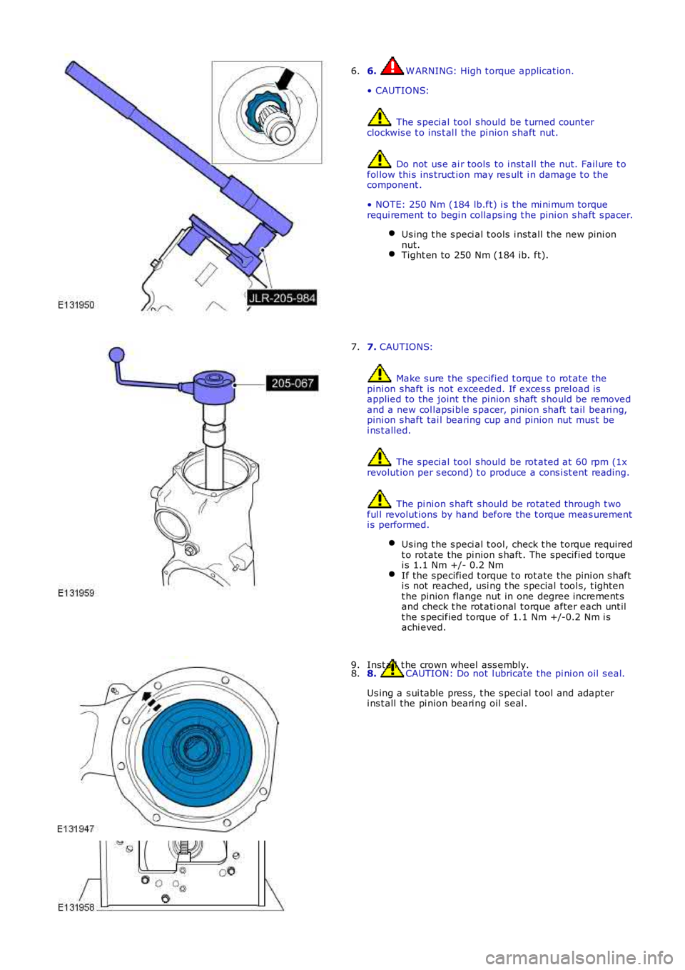
6. W ARNING: High t orque applicat ion.
• CAUTIONS:
The s peci al tool s hould be t urned count erclockwis e t o ins t al l the pi nion s haft nut.
Do not us e ai r tools to i nst all t he nut. Fail ure t ofol low thi s ins truct ion may res ult i n damage t o thecomponent .
• NOTE: 250 Nm (184 lb.ft) i s t he mi ni mum torquerequi rement to begi n collaps ing t he pini on s haft s pacer.
Us ing t he s peci al t ools i nst all t he new pini onnut.Tight en to 250 Nm (184 ib. ft).
6.
7. CAUTIONS:
Make s ure the specified t orque t o rot ate thepini on s haft is not exceeded. If exces s prel oad isapplied to the joint t he pinion s haft s hould be removedand a new col lapsi ble s pacer, pinion shaft tail beari ng,pini on s haft tai l bearing cup and pinion nut mus t bei ns t alled.
The s peci al tool s hould be rot ated at 60 rpm (1xrevolut ion per s econd) t o produce a cons i st ent reading.
The pi ni on s haft s houl d be rotat ed through t woful l revolut ions by hand before the t orque meas urementi s performed.
Us ing t he s peci al t ool, check t he t orque requiredt o rot ate the pi nion s haft . The specified t orquei s 1.1 Nm +/- 0.2 NmIf the s pecifi ed t orque t o rot ate the pi ni on s hafti s not reached, usi ng t he s pecial t ool s, t ight ent he pinion flange nut in one degree increment sand check t he rot ati onal t orque after each unt ilt he s pecified t orque of 1.1 Nm +/-0.2 Nm i sachi eved.
7.
8. CAUTION: Do not l ubricate the pi ni on oil s eal.
Us ing a s ui table pres s, t he s peci al t ool and adapt eri ns t all the pi nion beari ng oil s eal .
8.Inst all t he crown wheel ass embly.9.
Page 420 of 3229
Publi s hed: 11-May-2011
Front Disc Brake -
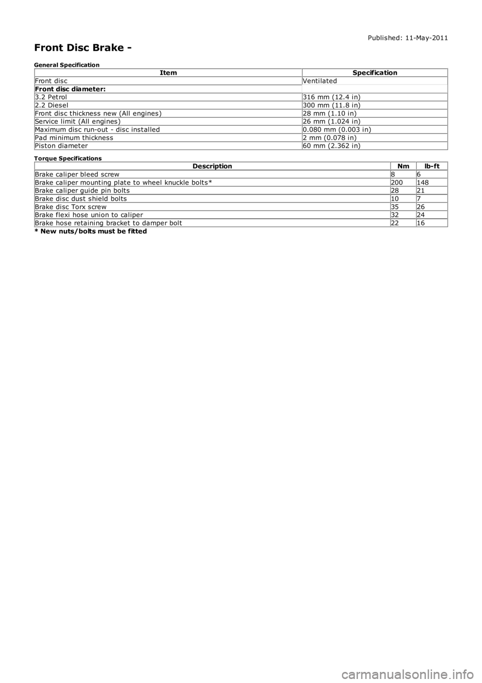
General SpecificationItemSpecification
Front dis cVenti lated
Front disc diameter:3.2 Pet rol316 mm (12.4 i n)
2.2 Dies el300 mm (11.8 i n)
Front dis c t hicknes s new (All engines )28 mm (1.10 i n)Service l imit (All engi nes )26 mm (1.024 i n)
Maximum dis c run-out - dis c ins t al led0.080 mm (0.003 i n)
Pad mi nimum thi cknes s2 mm (0.078 i n)Pis t on diamet er60 mm (2.362 i n)
Torque SpecificationsDescriptionNmlb-ft
Brake cali per bl eed screw86
Brake cali per mount ing pl at e t o wheel knuckle bolt s *200148Brake cali per gui de pin bolt s2821
Brake di sc dus t s hield bol ts107
Brake di sc Torx s crew3526Brake flexi hose uni on to cal iper3224
Brake hos e retaini ng bracket t o damper bol t2216
* New nuts/bolts must be fitted
Page 433 of 3229
Publi s hed: 11-May-2011
Rear Disc Brake -
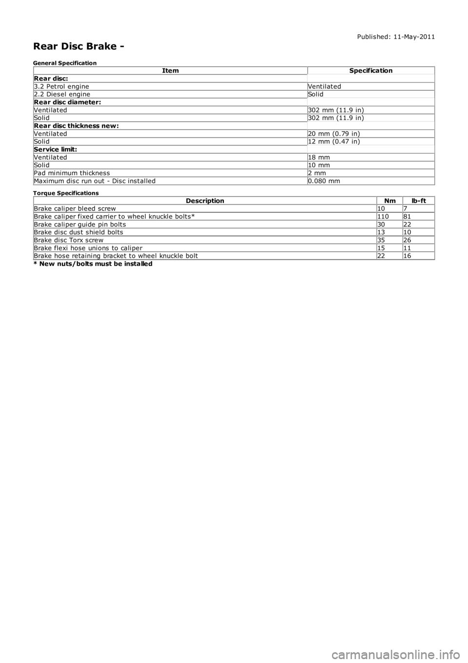
General SpecificationItemSpecification
Rear disc:
3.2 Pet rol engineVent il at ed2.2 Dies el engineSol id
Rear disc diameter:
Venti lat ed302 mm (11.9 in)Soli d302 mm (11.9 in)
Rear disc thickness new :
Venti lat ed20 mm (0.79 in)Soli d12 mm (0.47 in)
Service limit:
Venti lat ed18 mmSoli d10 mm
Pad mi nimum thi cknes s2 mm
Maximum dis c run out - Dis c ins t al led0.080 mm
Torque Specifications
DescriptionNmlb-ftBrake cali per bl eed screw107
Brake cali per fixed carrier t o wheel knuckl e bolt s*11081
Brake cali per gui de pin bolt s3022Brake di sc dus t s hield bol ts1310
Brake di sc Torx s crew3526
Brake flexi hose uni ons to cali per1511Brake hos e retaini ng bracket t o wheel knuckle bolt2216
* New nuts/bolts must be installed
Page 498 of 3229
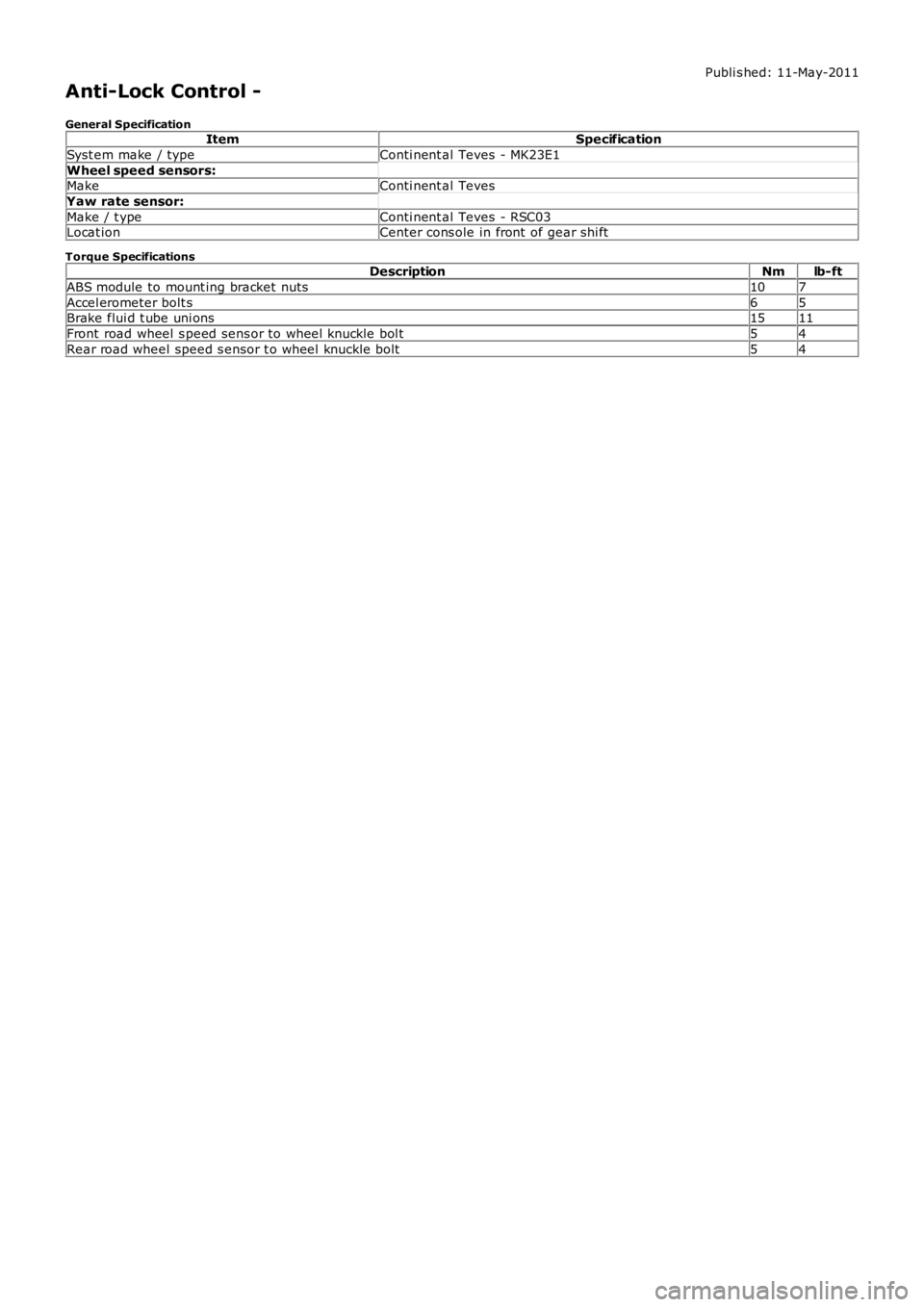
Publi s hed: 11-May-2011
Anti-Lock Control -
General SpecificationItemSpecification
Syst em make / typeConti nent al Teves - MK23E1
Wheel speed sensors:MakeConti nent al Teves
Yaw rate sensor:
Make / t ypeConti nent al Teves - RSC03Locat ionCenter cons ole in front of gear shi ft
Torque SpecificationsDescriptionNmlb-ft
ABS module to mount ing bracket nuts107
Accel erometer bolt s65Brake flui d t ube uni ons1511
Front road wheel s peed sens or to wheel knuckle bol t54
Rear road wheel speed s ensor t o wheel knuckle bolt54
Page 511 of 3229
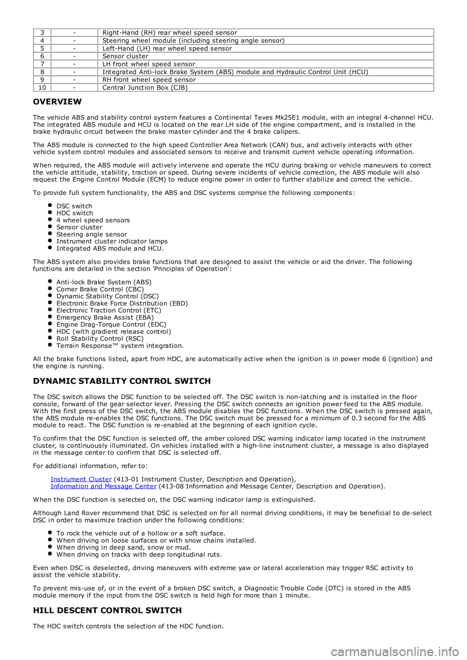
3-Right -Hand (RH) rear wheel s peed s ens or
4-Steering wheel modul e (including s t eering angle sens or)
5-Left -Hand (LH) rear wheel s peed s ens or6-Sensor clus ter
7-LH front wheel speed s ensor
8-Int egrat ed Anti -l ock Brake Sys t em (ABS) modul e and Hydrauli c Cont rol Unit (HCU)9-RH front wheel speed s ensor
10-Central Junct ion Box (CJB)
OVERVIEW
The vehi cl e ABS and s t abi li ty control sys tem feat ures a Cont inental Teves Mk25E1 module, wi th an int egral 4-channel HCU.The int egrated ABS modul e and HCU is l ocat ed on t he rear LH s ide of t he engine compart ment, and i s ins tal led i n t hebrake hydrauli c ci rcuit bet ween the brake mas ter cyl inder and the 4 brake calipers.
The ABS module is connect ed to the hi gh s peed Cont roll er Area Net work (CAN) bus , and acti vel y int eracts wi th othervehi cl e s yst em cont rol modules and as sociat ed s ens ors to recei ve and transmit current vehicle operat ing informati on.
W hen requi red, t he ABS module wi ll acti vel y int ervene and operate the HCU during braki ng or vehi cl e maneuvers t o correctt he vehi cl e att it ude, s t abi li ty, t racti on or speed. During severe incident s of vehicle correct ion, t he ABS module will al soreques t the Engine Cont rol Modul e (ECM) to reduce engi ne power i n order t o further stabil ize and correct t he vehicle.
To provide full s ys tem functi onali ty, t he ABS and DSC s ys tems compris e t he fol lowing component s :
DSC s wit chHDC s wi tch4 wheel s peed s ens orsSens or clus terSteering angle s ens orIns t rument clus ter i ndi cat or lampsInt egrat ed ABS module and HCU.
The ABS s yst em al s o provides brake funct ions t hat are des igned to ass is t t he vehi cle or aid the driver. The followi ngfuncti ons are det ai led i n t he s ect ion 'Principl es of Operati on':
Anti -l ock Brake Sys t em (ABS)Corner Brake Control (CBC)Dynamic St abi li ty Cont rol (DSC)Electroni c Brake Force Di s tributi on (EBD)Electroni c Tracti on Control (ETC)Emergency Brake As s is t (EBA)Engi ne Drag-Torque Control (EDC)HDC (wit h gradi ent releas e cont rol )Roll Stabi lit y Control (RSC)Terrai n Res pons e™ sys tem int egrati on.
All t he brake funct ions li s ted, apart from HDC, are automat icall y act ive when t he i gni ti on is in power mode 6 (igni ti on) andt he engi ne is runni ng.
DYNAMIC STABILITY CONTROL SWITCH
The DSC s wit ch all ows the DSC functi on to be s elect ed off. The DSC s wi tch i s non-latchi ng and is i nst all ed in the floorcons ole, forward of the gear s el ect or lever. Pres s ing t he DSC s wi tch connects an ignit ion power feed to t he ABS modul e.W i th the firs t pres s of the DSC swit ch, t he ABS module di sabl es the DSC funct ions . When t he DSC s wi tch i s pres sed agai n,t he ABS module re-enables t he DSC funct ions. The DSC swi tch must be press ed for a minimum of 0.3 s econd for the ABSmodule t o react . The DSC functi on is re-enabled at t he beginning of each ignit ion cycle.
To confirm that t he DSC functi on is sel ect ed off, the amber colored DSC warni ng indicator l amp located i n t he ins t rumentclus ter, is conti nuous ly i ll uminated. On vehicles i nst all ed wit h a hi gh-li ne ins t rument clus ter, a mes sage i s als o di spl ayedin the mess age cent er to confirm t hat DSC is s elect ed off.
For addit ional informat ion, refer t o:
Ins trument Clus ter (413-01 Ins t rument Clus t er, Descripti on and Operat ion),Informat ion and Mes s age Cent er (413-08 Informati on and Mes sage Cent er, Descripti on and Operat ion).
W hen t he DSC funct ion i s s elected on, t he DSC warni ng indicator l amp is ext inguis hed.
Alt hough Land Rover recommend t hat DSC is s elected on for all normal driving condit ions, i t may be benefi ci al t o de-sel ectDSC i n order t o maximi ze tract ion under t he foll owing condit ions:
To rock t he vehicle out of a holl ow or a s oft surface.W hen driving on loose s urfaces or wit h s now chains ins t al led.W hen driving i n deep s and, s now or mud.W hen driving on tracks wi th deep l ongi tudinal rut s .
Even when DSC is des elected, dri ving maneuvers wi th ext reme yaw or lateral acceleration may trigger RSC act ivit y t oas si st the vehicle st abili ty.
To prevent mis -use of, or in the event of a broken DSC s wit ch, a Diagnost ic Troubl e Code (DTC) i s s tored in the ABSmodule memory i f the input from t he DSC s wit ch is hel d high for more than 1 minut e.
HILL DESCENT CONTROL SWITCH
The HDC s wi tch control s t he s el ect ion of t he HDC funct ion.
Page 522 of 3229

12-LH front wheel s peed s ens or
13-RH rear wheel s peed sens or
14-Act ive On-Demand Coupling modul e15-ECM
16-Diagnost ic socket
17-Sens or clus ter18-Terrai n Res pons e™ control modul e
19-Trans mis s ion Cont rol Modul e (TCM) - aut omati c t rans mis s ion models onl y
20-CJB
PRINCIPLES OF OPERATION
Anti-Lock Brake System
ABS cont rol s t he s peed of all road wheel s t o ensure opti mum wheel s li p when braking at the adhesi on li mit . The wheelsare prevent ed from locki ng to ret ai n effecti ve st eeri ng cont rol of the vehicle.
The front brake pres s ures are modul ated s eparat el y for each wheel. The rear brake press ures are modulat ed by s elect low.Select low appli es the same pres sure t o both rear brakes, wi th the press ure level bei ng det ermined by t he wheel on thelower fri ct ion s urface. This maint ai ns rear s tabil it y on s pli t fricti on s urfaces .
Corner Brake Control
CBC i nfluences the brake pres sures , below and wit hin ABS thres holds , to counteract the yawing moment produced whenbraking i n a corner. CBC produces a correcti on t orque by li mi ti ng the brake pres sure on one s ide of t he vehicle.
Dynamic Stability Control
DSC us es brakes and powert rain torque control to as s is t i n maint aining the l ateral st abi lit y of t he vehi cl e. W hil e t heignit ion is energi zed t he DSC funct ion i s permanentl y enabl ed, unl es s s elect ed off us ing t he DSC s wit ch. Even i f DSC isdesel ect ed, driving maneuvers wi th ext reme yaw or lat eral accelerat ion may trigger RSC acti vi ty to as s is t t he vehi cl es tabil it y.
DSC enhances dri ving s afet y in abrupt maneuvers and in under-st eer or over-s teer s ituat ions t hat may occur in a bend. TheABS module monit ors t he yaw rat e and l ateral accel erati on of the vehicle, s t eering input , and then s elect ively appli esindivi dual brakes and s ignals for powertrain t orque adjus t ments t o reduce under-s teer or over-s teer.
In general:
In an under-s t eer s i tuati on; the i nner wheels are braked t o count eract the yaw movement t owards t he outer edgeof the bend.In an over-st eer si tuat ion; the out er wheel s are braked to prevent t he rear end of the vehicl e from pus hing t owardst he out er edge of t he bend.
The ABS module monit ors t he tracki ng s tabil it y of the vehicle usi ng inputs from t he wheel s peed s ens ors, t he s teeringangl e s ensor, and the yaw rat e and lat eral accelerat ion sens or. The t racki ng s tabil it y is compared wit h s t ored t arget dat a.W henever t he t racki ng s tabil it y devi ates from t he target dat a, t he ABS modul e int ervenes by appl yi ng the appropriat ebrakes.
The fol lowing interact ions occur i n an i nt erventi on s it uat ion:
High speed CAN s i gnal t o t he ECM, to reduce engine torque.High speed CAN s i gnal t o t he Act ive On-demand Coupl ing module, t o open t he locki ng torque of the centercoupl ing.Applicati on of braking t o t he appropri at e corner of the vehicl e.
Electronic Brake Force Distribution
EBD l imi ts the brake press ure appl ied t o t he rear wheels . W hen t he brakes are appl ied, the wei ght of t he vehicle t rans fersforwards , reduci ng t he abi li ty of t he rear wheels to t rans fer braki ng effort t o t he road s urface. This may caus e t he rearwheels t o s li p and make t he vehi cl e uns table.
EBD us es the ant i-lock braking hardware t o automat icall y opti mize t he pres s ure of t he rear brakes , bel ow t he point whereABS i s normall y i nvoked.
• NOTE: Only the rear brakes are control led by the EBD funct ion.
Electronic Traction Control
ETC att empt s to opt imize forward tract ion by reduci ng engi ne torque, or by applying t he brake of a spi nni ng wheel unt ilt racti on is regai ned.
ETC is act ivated if an i ndi vi dual wheel speed i s above that of the vehicle reference speed (pos i ti ve sl ip) and t he brakepedal i s not pres sed. The brake i s appl ied t o t he s pinning wheel, al lowing t he excess t orque t o be t rans mit t ed to thenon-s pinning wheels through t he dri ve li ne. If neces s ary, the ABS modul e als o s ends a hi gh speed CAN bus mess age t ot he ECM t o reques t a reducti on in engine torque.
W hen t he DSC funct ion i s s elected off us i ng the DSC s wit ch, t he engi ne t orque reducti on feature i s dis abl ed.
Emergency Brake Assist
EBA as si s ts t he driver in emergency braking si tuat ions by automat icall y maximi zi ng the appl ied braki ng effort . There aret wo s it uat ions when t he ABS module wil l invoke EBA:
Page 523 of 3229
W hen t he brake pedal is rapi dly press ed.W hen t he brake pedal is pres s ed hard enough t o bri ng t he front brakes i nto ABS operati on.
W hen t he brake pedal is rapi dly press ed, the ABS modul e i ncreas es t he hydraul ic press ure to al l of the brakes unt il t het hreshol d for ABS operat ion i s reached. This act ion appli es the maxi mum braking effort for the avail abl e t racti on. The ABSmodule moni tors for t he s udden appli cat ion of t he brakes , us i ng inputs from t he brake pedal s wi tch and from the press ures ens or wit hin the HCU. W it h t he brake pedal pres s ed, if t he rat e of increas e of hydraul ic press ure exceeds thepredetermined l imi t, t he ABS modul e invokes emergency braki ng.
W hen t he brake pedal is pres s ed hard enough t o bri ng t he front brakes i nto ABS operati on, t he ABS module increas es thehydraulic press ure to the rear brakes up to the ABS thres hold.
EBA operat ion cont inues unti l the driver rel eas es t he brake pedal , s uffi cientl y for t he hydraulic press ure in the HCU to dropbelow a threshold val ue s tored in t he ABS modul e.
Engine Drag-Torque Control
EDC prevents wheel s li p caus ed by any of t he fol lowing:
A s udden decreas e i n engine t orque when t he accelerator is suddenly released.The s udden engagement of t he clutch after a downs hift on manual t rans mi ss ion vehicl es .A downs hift us i ng the CommandShift functi on on automat ic t rans mi ss ion vehicl es .
W hen t he ABS module det ects t he ons et of wheel s lip wit hout t he brakes being appli ed, t he ABS module s ignal s t he ECMvia t he high speed CAN bus t o reques t a moment ary increase in engine torque.
Hill Descent Control
HDC us es engine braking and brake int ervent ion to control the vehicle speed and accel erati on duri ng low speed off-roaddescents , and in low grip on-road condit ions. General ly, equal pres s ure i s applied to al l 4 brakes , but pres s ure to individualbrakes may be modi fi ed by t he ABS and DSC funct ions to ret ain t he vehi cles s tabil it y. Sel ect ion of t he HDC funct ion i scont rol led by t he HDC s wi tch l ocat ed on t he fl oor consol e. HDC operates at vehicle speeds up t o 50 km/h (31 mph).
W ARNING: Incorrect us e of the HDC functi on may compromis e t he s tabil it y of the vehicle, resul ti ng in a dangerousand uncont roll ed hil l des cent . Pres si ng t he cl utch pedal and/or driving wit h t he trans mi s si on in 'Neutral' whil e HDC i sact ive, wi ll prevent engine braking from ass is t ing t he vehicle. The brakes wil l overheat and i nduce t he HDC fade outs trategy. In this condit ion t here will be no cont rol over t he vehi cl e duri ng a des cent .
• NOTE: W i th the HDC functi on s elect ed, HDC i s operati ve even when the clut ch pedal is pres sed or t he t rans mis s ion i s int he 'Neutral' posi ti on. It is not recommended t o drive t he vehi cl e furt her t han is abs olut el y neces s ary wi th HDC s elected,and t he cl utch pedal press ed/ or the t rans mi ss i on in 'Neut ral '.
On manual transmis s ion vehicles , HDC may be us ed i n firs t and reverse gears only. Once the vehicle is movi ng, t he clut chpedal i s to be ful ly releas ed. The vehicle i s not recommended to be dri ven wit h HDC act ive and t he transmis si on in'Neut ral'.
On aut omati c trans mi s si on vehi cl es, HDC may be us ed i n 'D' dri ve, 'R' revers e and CommandShi ft '1' only. W hen in 'D', t heTCM wi ll automat icall y s el ect t he mos t appropri ate gear. The vehicle is not recommended t o be driven wit h HDC act ive andt he trans mi s si on in 'Neutral'.
HDC i s able t o be sel ect ed at speeds up t o 80 km/h (50 mph), but wi ll only be enabled at s peeds bel ow 50 km/h (31 mph).
W hen HDC is s elect ed:
At s peeds up t o 50 km/h (31 mph), the HDC informat ion i ndi cat or lamp i s permanentl y i llumi nated i f a valid gear i ss elect ed.At s peeds bet ween 50 to 80 km/h (31 to 50 mph), t he HDC i nformat ion indicator lamp fl ashes and on vehicles wit ht he high l ine i ns t rument clus ter, a mes s age advis i ng that t he s peed i s t oo high i s dis played in the mes s age cent er.If the HDC swit ch is pres s ed whil e t he vehi cl e s peed is great er than 80 km/h (50 mph), the HDC informat ionindicat or l amp wi ll not il lumi nat e and HDC will not be s elected.If the s peed reaches 80 km/h (50 mph) or more, a warni ng chi me i s s ounded, the HDC functi on is swi tched off, t heinformat ion i ndi cat or lamp is exti ngui shed and, on vehicles wi th the hi gh li ne ins trument cl ust er, a mess ageadvi s ing t hat HDC has been swi tched off i s dis played i n the mess age center.
For addit ional informat ion, refer t o:
Ins trument Clus ter (413-01 Ins t rument Clus t er, Descripti on and Operat ion),Informat ion and Mes s age Cent er (413-08 Informati on and Mes sage Cent er, Descripti on and Operat ion).
W hen HDC is enabled, the ABS module calculat es a t arget speed and compares t his wi th the act ual vehicle s peed. The ABSmodule t hen operates the HCU in t he acti ve braking mode as required, t o achi eve and maint ain t he t arget speed.Operat ion of t he vehi cl e s toplamps during HDC is controll ed by the CJB.
Applying t he foot brake during acti ve braking may res ult i n a puls e being felt t hrough t he brake pedal.
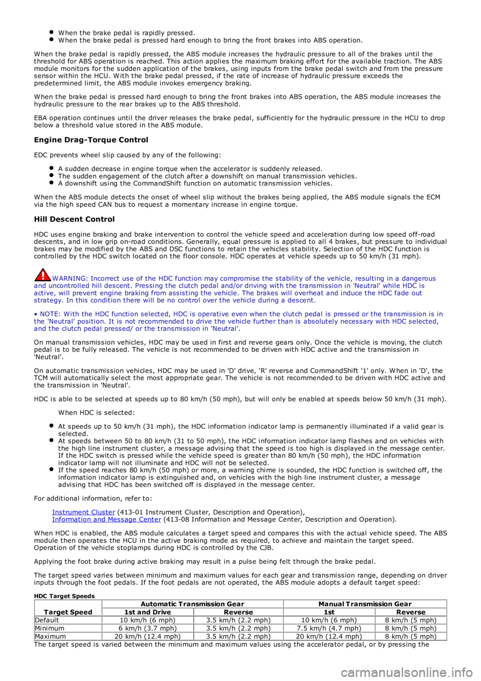
The t arget speed vari es bet ween mi nimum and maximum values for each gear and t rans miss ion range, dependi ng on driverinputs through t he foot pedals . If the foot pedals are not operated, t he ABS module adopts a default t arget s peed:
HDC Target Speeds
T arget Speed
Automatic T ransmission GearManual T ransmission Gear
1st and DriveReverse1stReverseDefaul t10 km/h (6 mph)3.5 km/h (2.2 mph)10 km/h (6 mph)8 km/h (5 mph)
Mi ni mum6 km/h (3.7 mph)3.5 km/h (2.2 mph)7.5 km/h (4.7 mph)8 km/h (5 mph)
Maximum20 km/h (12.4 mph)3.5 km/h (2.2 mph)20 km/h (12.4 mph)8 km/h (5 mph)The t arget speed i s varied bet ween the mini mum and maxi mum values us ing the accel erator pedal, or by pres s ing t he