Page 1409 of 3229
Publi s hed: 11-May-2011
Clutch -
Lubricants, Fluids, Sealers and AdhesivesItemSpecification
Recommended hydraul ic fluidSHELL DONAX Y B DOT4 ESL FLUID
General Specification
ItemSpecification
Clut ch make/t ypeLUK - Self adjus ti ng clutchClut ch s ize250 mm (9.84 in)
Clut ch plat e frict ion mat eri alVal eo 810 DS
Mas ter cylinder makeFTESlave cyli nder make/t ypeFTE Concent ric s lave cylinder
Torque Specifications
DescriptionNmlb-ft
Clut ch cover t o fl ywheel bolt s - vehi cles buil t up to 11MY * +2317Clut ch cover t o fl ywheel bolt s - vehi cles buil t 11MY onwards* +2921
* T ighten bolts progressively by diagonal selection.
+ New bolts must be installed.
Page 1487 of 3229
t he power t rans fer unit .
The crown wheel is support ed in the cas ing on opposi ng t aper rol ler beari ngs whi ch are press ed i nto t he casi ng and t hehous i ng. The drive gear is retained i n t he cas i ng by a housi ng which i s bolt ed to the cas ing and s ealed wi th an O ring seal.The hous i ng is fit t ed wit h a t riple edge oi l seal and fl inger on the out er end of the hous ing which di rect dirt and mois tureaway from the area of the drive gear. Another s eal i s fit ted whi ch prevent s t he ingres s of dirt and mois t ure bet ween thedri ve gear and t he RH hal f shaft .
The pinion gear i s located i n t he hous ing at 90 degrees to the crown wheel drive gear. The pini on gear i s s upport ed i n t hecas i ng on oppos ing taper roll er bearings . The pi nion gear is retai ned in t he housi ng wit h a pre-l oad nut . The outer end oft he pinion gear is spl ined and mat es wit h t he dri ve shaft out put fl ange. The fl ange is s ecured wi th a fl anged bol t which iss crewed int o t he pinion gear.
A coll aps i bl e s pacer is locat ed between the out er t aper roll er beari ng and a s houlder on the pi nion gear. The coll aps ibl es pacer holds t he bearing i n ali gnment and al so col laps es under pres s ure appli ed to the pre-l oad nut . This all ows t hepre-load nut to be t ightened t o a predet ermi ned torque, which coll aps es t he s pacer, s et ti ng the correct bearing pre-loadand t he correct mes hi ng of the pi nion gear and crown wheel drive gear t eet h.
Dri ve from the t rans mis s ion di fferenti al drives t he crown wheel dri ve gear, which in turn rot ates t he pini on gear. Dri ve ispass ed from the pi nion gear to the drive s haft and t he rear different ial via the drive flange att ached to t he pini on gears haft.
Page 1828 of 3229
1. Apply parki ng brake oralt ernat ively, chock wheels1. Ens ure t hat al l elect rical l oads are s wit ched OFF
2. Open t he hood2. Connect batt ery leads - GROUND l ead las t3. Dis connect batt ery -GROUND lead firs t3. Swit ch on i gni ti on
4. Res et radio s t ati on pres et but tons .
5. Res et cl ock
6. Res et el ect ri c window one-touch facil it y. Power wi ndow up to hard s t op, release swit ch,reapply and hol d for 1 s econd (relay i n door wil l cl ick). Lower window t o s top, reapply andhold for one s econd. One t ouch s houl d now work
Procedure 5
Disconnect batteryConnect battery1. Apply parki ng brake oralt ernat ively, chock wheels1. Ens ure t hat al l elect rical l oads are s wit ched OFF
2. Open t he hood2. Connect batt ery leads - GROUND l ead las t
3. Dis connect batt ery -GROUND lead firs t3. Swit ch on i gni ti on
4. Res et radio s t ati on pres et but tons .
5. Res et cl ock
6. Res et el ect ri c window one-touch facil it y. Power wi ndow up to hard s t op, release swit ch,reapply and hol d for 1 s econd (relay i n door wil l cl ick). Lower window t o s top, reapply andhold for one s econd. One t ouch s houl d now work
Torque SpecificationsDescriptionNmlb-ft
Batt ery tray to support bracket107
Batt ery terminal nut s107Battery support bracket to body:
M8 nut2418
M8 bol t2418
Page 2704 of 3229
18. WARNING: Make sure that a new steering column flexible coupling bolt is
installed.
Connect the steering column to the steering gear.
Torque: 25 Nm18.
Connect and s ecure t he cat alys t moni t or s ens or el ect ri cal connect ors . 19.
Install the 2 subframe mounting bolts and remove the jack. 20.
Install the engine undershield.
Refer to: Engine Undershield
(501-02 Front End Body Panel s, Removal and
Installation). 21.
Install the wheels and tires.
Refer to: W heel and Tire
(204-04 W heels and Tires , Removal and Ins t all at i on). 22.
Refill and bleed the power steering.
Refer to: Power Steering System Bleeding
(211-00 St eeri ng Sys t em - General
Informat ion, General Procedures). 23.
Using only four wheel alignment equipment approved by Land Rover, check and adjust
the wheel alignment. 24.
Page 2715 of 3229
1. CAUTION: Make sure that new bolts are installed.
Clean the component mating faces.
With assistance, install the subframe.With assistance, align and secure the differential.Tighten the rear bolts.
Torque: 110 Nm
Tighten the front bolts.
Torque: 175 Nm
1.
2.
CAUTION: Make sure that new bolts are installed.
Align the suspension arms to the subframe and install the bolts, do
not fully tighten at this stage. 2.
Using the special tool, support the subframe. 3.
Connect the transmission breather lines. 4.
5. CAUTIONS:
Make sure that no components catch.
Make sure that new bolts are installed.
With assistance, position the subframe to the body and tighten the
bolts.
Torque: 175 Nm
5.
6.
CAUTION: Make sure that new bolts are installed.
Install the stabilizer clamp bolts, but do not tighten fully at this
stage. 6.
Connect the Active On-demand Coupling module electrical connector. 7.
Re mo ve t he p o we rt ra i n j a ck.
General Equi pment : P o w e rt ra i n Ja ck
8.
9.
CAUTION: Make sure that new bolts are installed.
Install the trailing arm to body brackets.
Torque: 110 Nm9.
10.
CAUTION: Make sure that the brake hose is not twisted
and is correctly located.
Clean the component mating faces.
Install the brake caliper anchor plate.
Torque: 110 Nm
Repeat the above procedure for the other side.
10.
Secure the wheel speed sensor and lead.
11.
Page 2716 of 3229
Torque: 5 NmSecure the lead in the clips.Repeat the above procedure for the other side.
LH side: Connect the ride height sensor electrical connector. 12.
Position and secure the rear shock absorbers.
Install both mass dampers.
Torque: 25 Nm
Repeat the above procedure for the other side.
13.
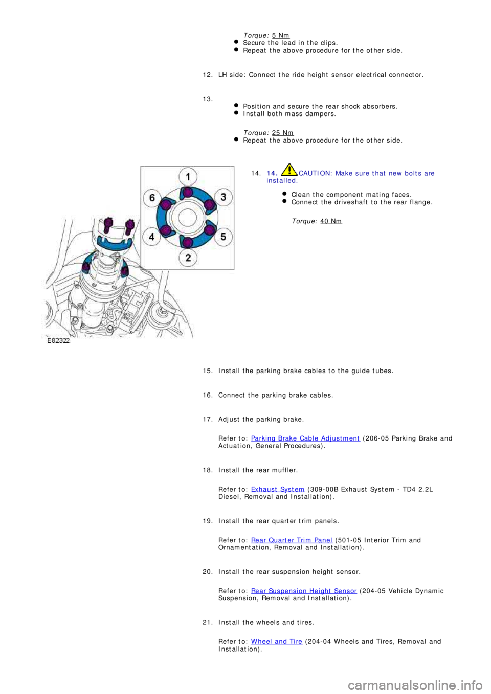
14. CAUTION: Make sure that new bolts are
installed.
Clean the component mating faces.
Connect the driveshaft to the rear flange.
Torque: 40 Nm
14.
Install the parking brake cables to the guide tubes. 15.
Connect the parking brake cables. 16.
Adjust the parking brake.
Refer to: Parking Brake Cable Adjustment
(206-05 Parki ng Brake and
Act uat i on, General Procedures ). 17.
Install the rear muffler.
Refer to: Exhaus t Sys t em
(309-00B Exhaus t Sys t em - TD4 2.2L
Diesel, Removal and Installation). 18.
Install the rear quarter trim panels.
Refer to: Rear Quarter Trim Panel
(501-05 Int eri or Tri m and
Ornament at i on, Removal and Ins t al lat i on). 19.
Install the rear suspension height sensor.
Refer to: Rear Suspension Height Sensor
(204-05 Vehi cl e Dynami c
Suspension, Removal and Installation). 20.
Install the wheels and tires.
Refer to: Wheel and Tire
(204-04 Wheels and Tires, Removal and
Installation). 21.
Page 2717 of 3229
22. CAUTION: Nuts and bolts must be tightened with the
weight of the vehicle on the suspension.
Tighten the stabilizer bar clamp bolts.
Torque: 60 Nm22.
23.
CAUTION: Nuts and bolts must be tightened with the
weight of the vehicle on the suspension.
Tighten the supsension arms to the subframe.
Torque: 175 Nm
During installation, do not tighten the nuts and bolts until
the 4 wheel alignment procedure has been carried out.
23.
Carry out a complete vehicle geometry check and adjustment. 24.
Page 2860 of 3229
Stability control
140
L
Stability controlPRINCIPLE OF OPERATION
Dynamic Stability Control (DSC)
DSC has two main functions.
Firstly, if a wheel, or wheels, loose traction
when accelerating, it enhances Traction
Control by reducing engine torque, and
applying braking force to individual wheels.
This further improves the vehicle's ability to
pull away on slippery, or loose surfaces, and
reduces the likelihood of wheel spin when
cornering.
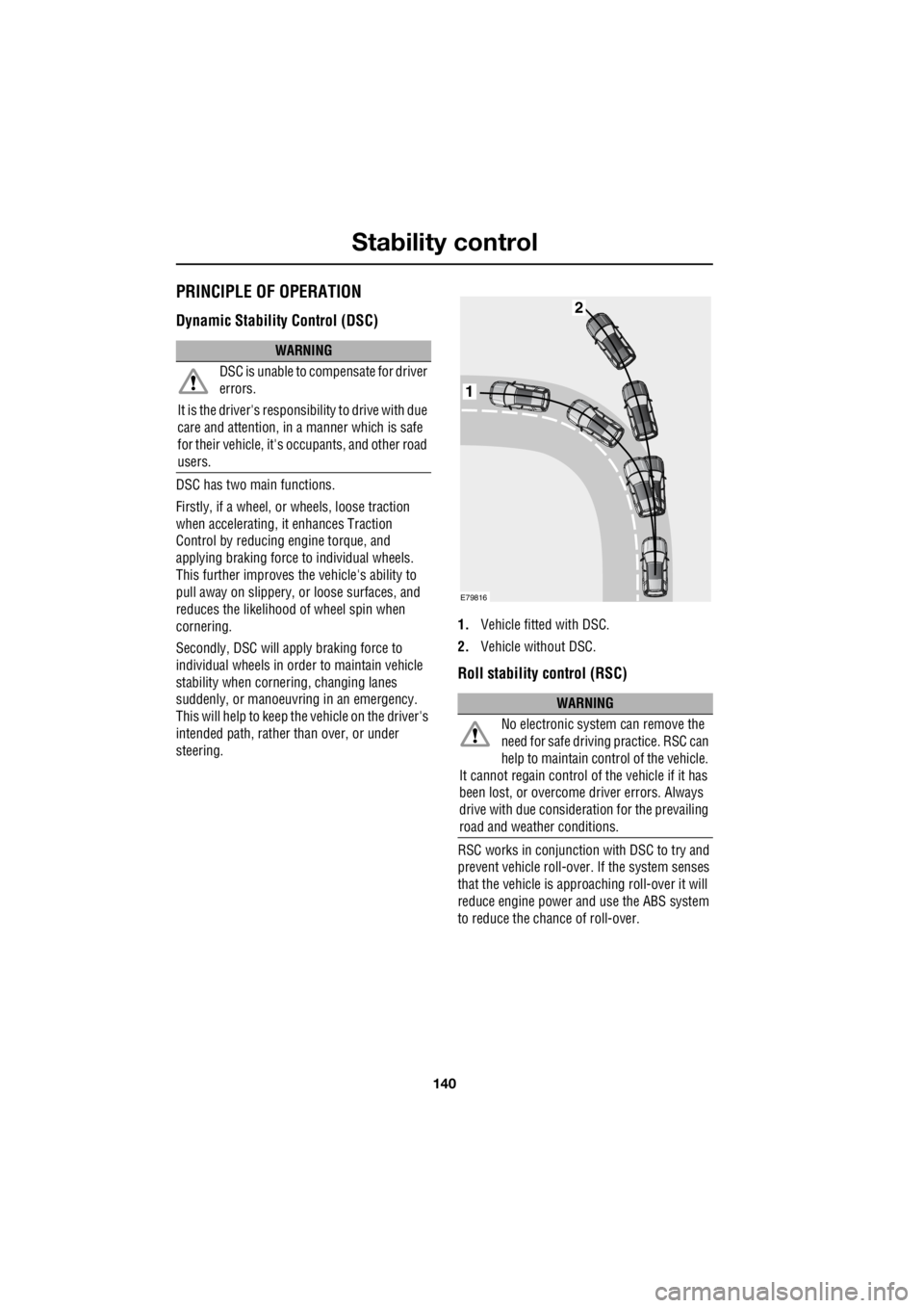
Secondly, DSC will apply braking force to
individual wheels in orde r to maintain vehicle
stability when cornering, changing lanes
suddenly, or manoeuvring in an emergency.
This will help to keep the vehicle on the driver's
intended path, rather than over, or under
steering. 1.
Vehicle fitted with DSC.
2. Vehicle without DSC.
Roll stability control (RSC)
RSC works in conjunction with DSC to try and
prevent vehicle roll-over. If the system senses
that the vehicle is approaching roll-over it will
reduce engine power and use the ABS system
to reduce the chance of roll-over.
WARNING
DSC is unable to compensate for driver
errors.
It is the driver's responsibility to drive with due
care and attention, in a manner which is safe
for their vehicle, it's oc cupants, and other road
users.
WARNING
No electronic system can remove the
need for safe drivin g practice. RSC can
help to maintain control of the vehicle.
It cannot regain control of the vehicle if it has
been lost, or overcome driver errors. Always
drive with due consideration for the prevailing
road and weather conditions.
1
2
E79816